
Experimental Investigation of the Effect of a Combination of Active and Passive Cooling Mechanism on the Thermal Characteristics and Efficiency of Solar PV Module

 ,
,  ,
,  , , and
Abstract
:1. Introduction
2. Materials and Methods
2.1. Mathematical Equations for PV Performance Calculations
2.2. Economic Analysis
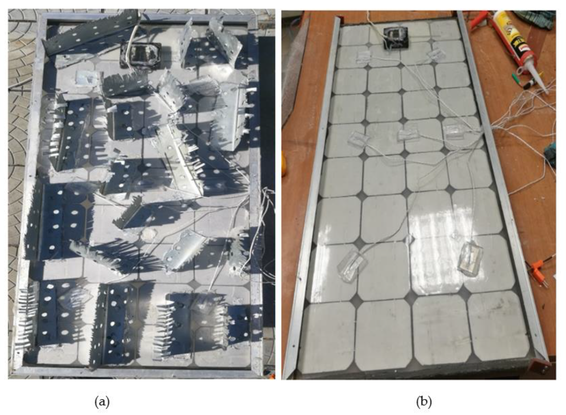
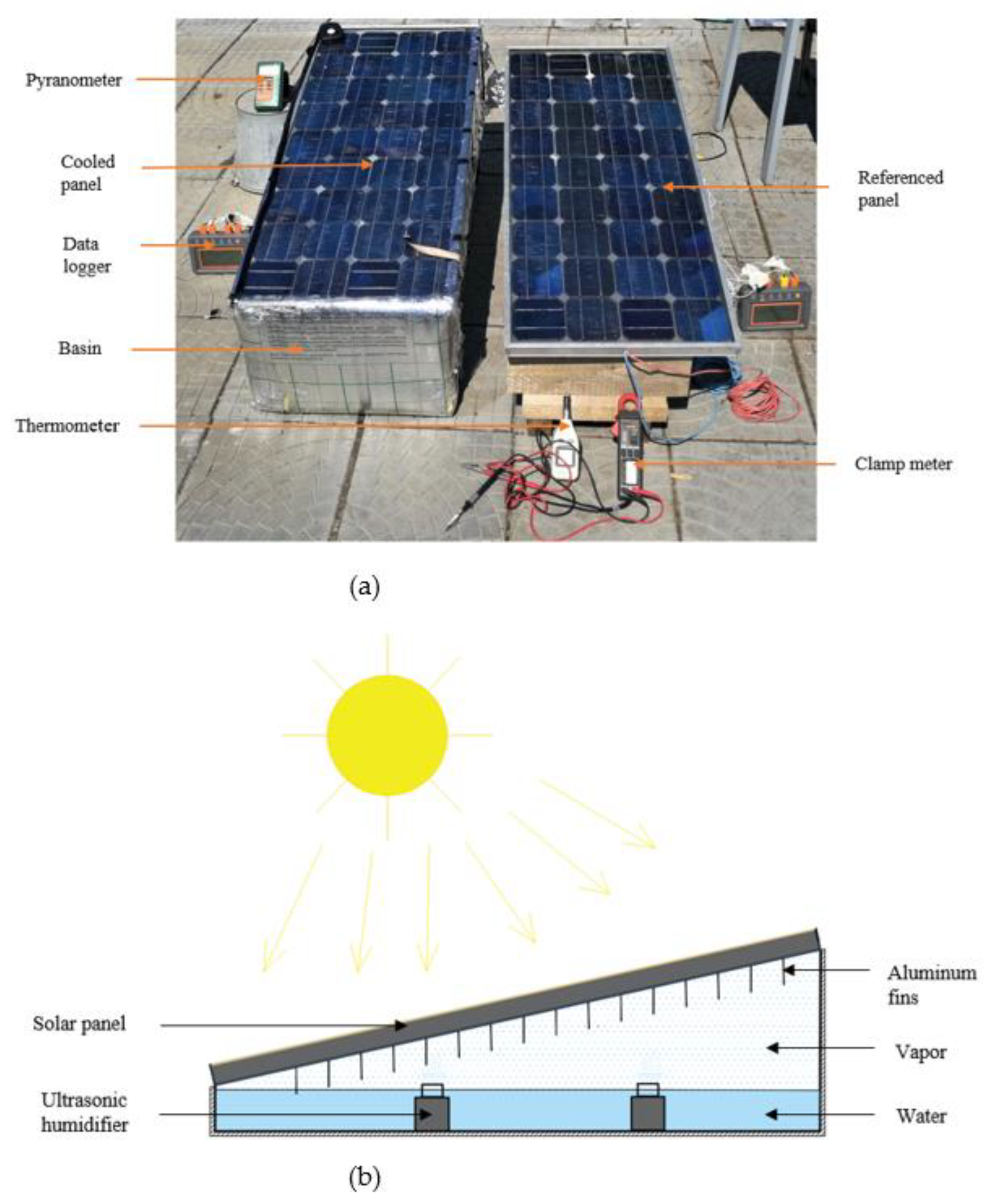
2.3. Construction of the Cooling System
2.4. Experimental Setup
2.5. Measurement Error Analysis
3. Results and Discussion
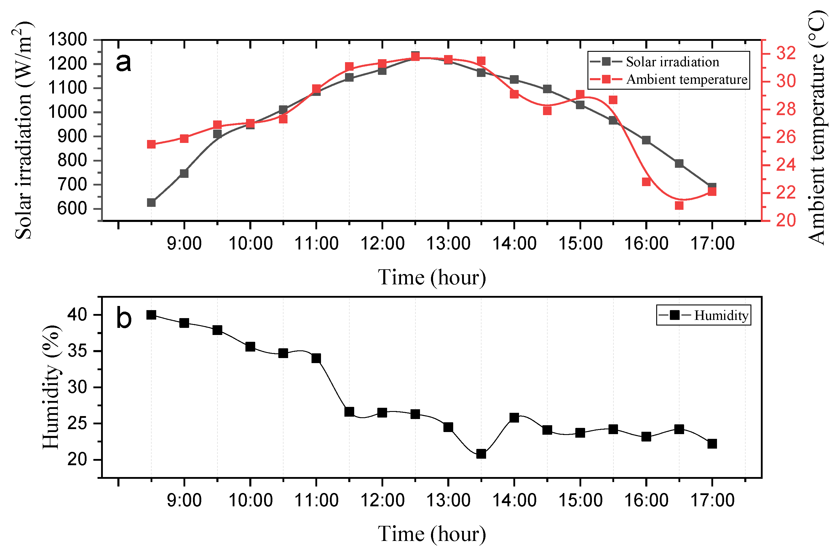
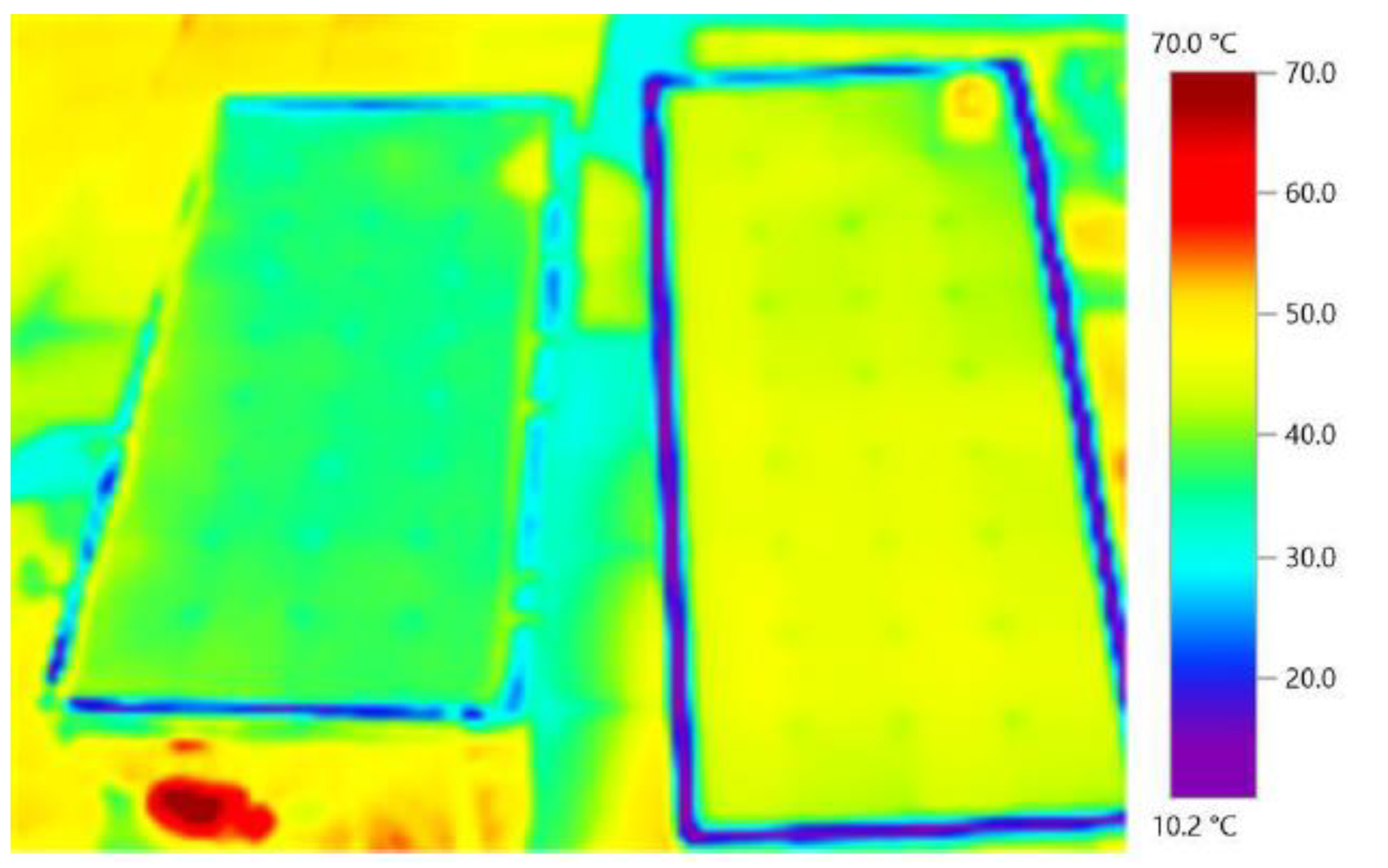
3.1. Impact of the Cooling Mechanism on Temperature of Panel
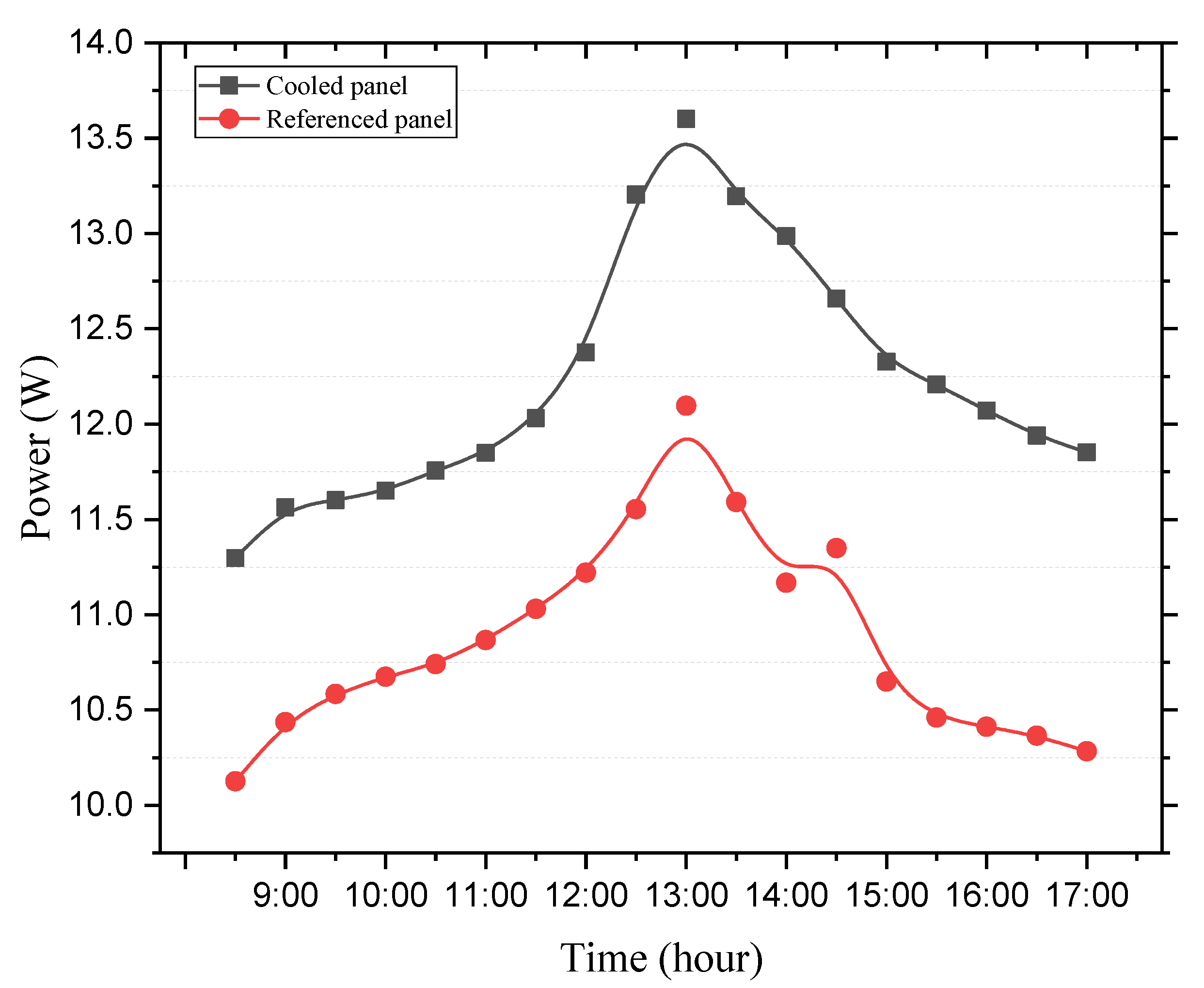
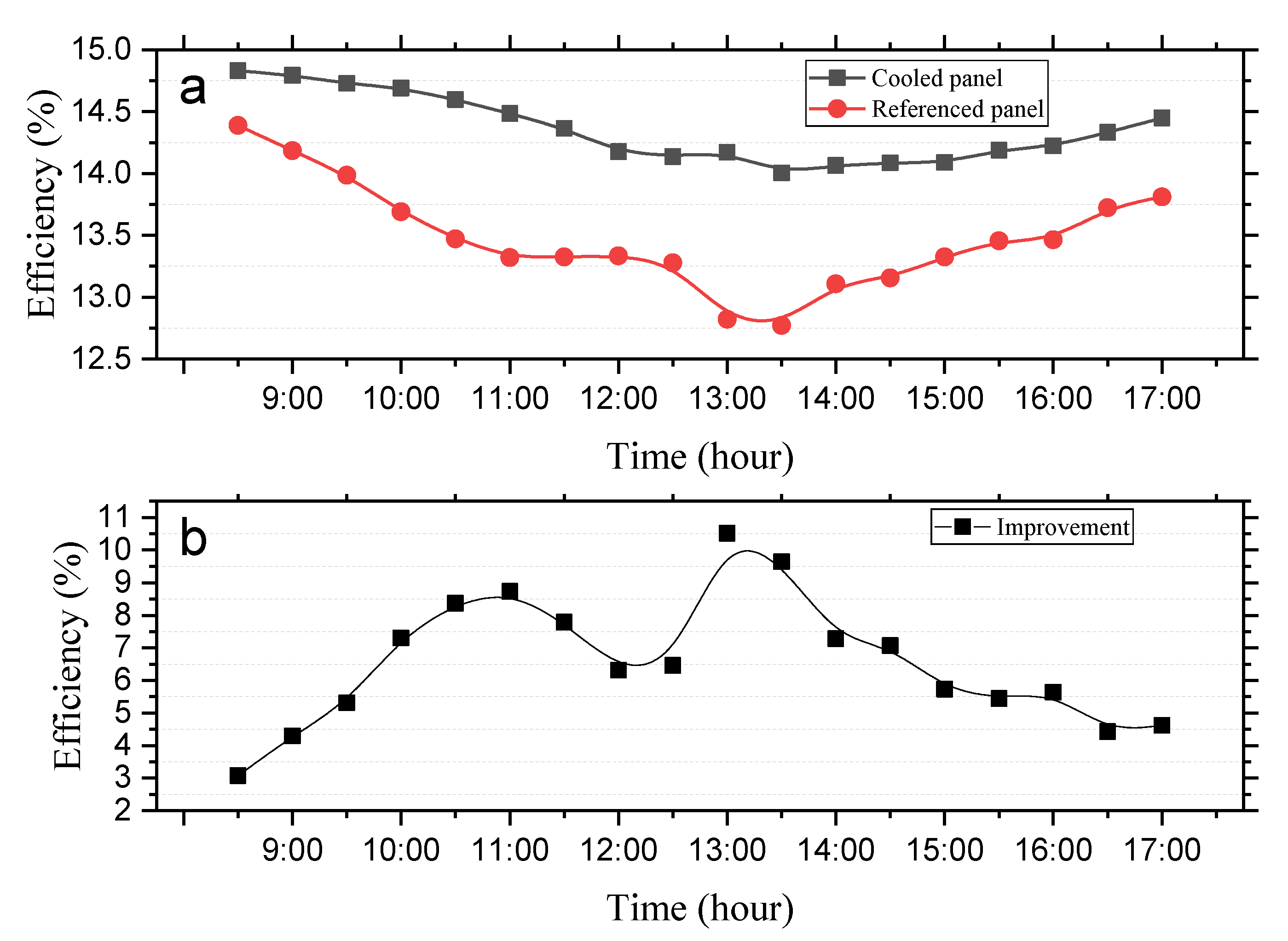
3.2. Electrical Analysis of both Panels
3.3. Water Consumption
3.4. Economic Analysis
4. Conclusions
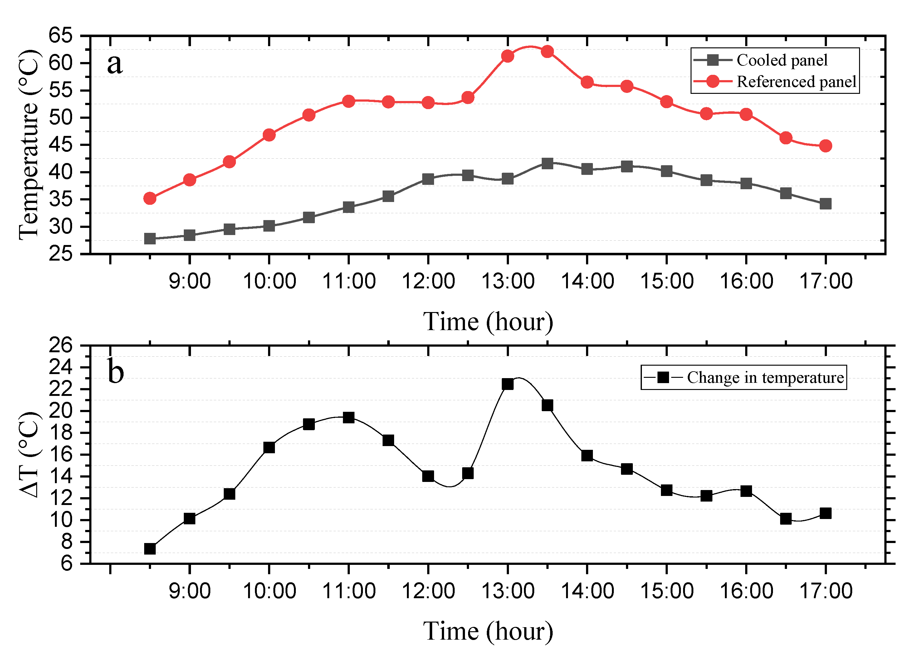
- The cooling process in the study was able to reduce the temperature of the panel averagely by 14.61 °C. This reduction led to a 6.8% improvement in the electrical efficiency of the module.
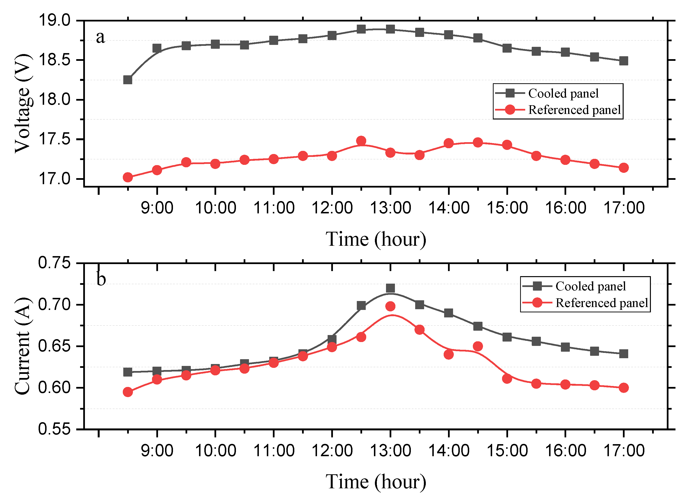
- The average voltage of the cooled panel for the entire experimental period is 18.69 V against 17.27 V for the referenced module. In effect, it can be said that the lack of cooling on the referenced module led to a drop of 1.42 V in its output voltage.
- The difference in the current of both modules were insignificant compared to the voltage, and this is expected.
- An average power of 12.23 W was recorded for the cooled panel against 10.87 W for the referenced module. This represents an improvement of 12.51% in the power output of the module due to the integration of the proposed cooling mechanism.
- By the calculations an LCE of 0.478 $/kWh will be the cost of the PV system for the 120 days and 0.210 $/kWh for a 365-day period for a total of 9 h of energy generation.
- In terms of water consumption, a total of 1.5 L was approximately consumed during the whole experimental process.
- Future studies can take into consideration the effect of the distance between the panel and the ultrasonic humidifier on the temperature variation of the module. Similarly, the effect of the thickness of the aluminum sheet used as fins can also be assessed to obtain the appropriate thickness for future implementation. Additionally, the effect of humidity and wind speed on the cooling process should be looked at during future studies that uses the proposed cooling mechanism. Furthermore, the effect of the arrangement of the aluminum fins and shapes and sizes can also be assessed in future studies.
Author Contributions
Funding
Conflicts of Interest
References
- BP. Statistical Review of World Energy|Energy Economics|Home. 2018. Available online: https://www.bp.com/en/global/corporate/energy-economics/statistical-review-of-world-energy.html (accessed on 15 January 2021).
- Agyekum, E.B. Energy poverty in energy rich Ghana: A SWOT analytical approach for the development of Ghana’s renewable energy. Sustain. Energy Technol. Assess. 2020, 40, 100760. [Google Scholar] [CrossRef]
- Agyekum, E.B.; Velkin, V.I. Optimization and techno-economic assessment of concentrated solar power (CSP) in South-Western Africa: A case study on Ghana. Sustain. Energy Technol. Assess. 2020, 40, 100763. [Google Scholar] [CrossRef]
- Adebayo, T.S.; Awosusi, A.A.; Oladipupo, S.D.; Agyekum, E.B.; Jayakumar, A.; Kumar, N.M. Dominance of Fossil Fuels in Japan’s National Energy Mix and Implications for Environmental Sustainability. Int. J. Environ. Res. Public Health 2021, 18, 7347. [Google Scholar] [CrossRef]
- Alwan, N.T.; Shcheklein, S.E.; Ali, O.M. Experimental investigation of modified solar still integrated with solar collector. Case Stud. Therm. Eng. 2020, 19, 100614. [Google Scholar] [CrossRef]
- Alwan, N.T.; Shcheklein, S.E.; Ali, O.M. Experimental analysis of thermal performance for flat plate solar water collector in the climate conditions of Yekaterinburg, Russia. Mater. Today Proc. 2021, 42, 2076–2083. [Google Scholar] [CrossRef]
- Amjad, F.; Agyekum, E.B.; Shah, L.A.; Abbas, A. Site location and allocation decision for onshore wind farms, using spatial multi-criteria analysis and density-based clustering. A techno-economic-environmental assessment, Ghana. Sustain. Energy Technol. Assess. 2021, 47, 101503. [Google Scholar] [CrossRef]
- Adebayo, T.S.; Agboola, M.O.; Rjoub, H.; Adeshola, I.; Agyekum, E.B.; Kumar, N.M. Linking Economic Growth, Urbanization, and Environmental Degradation in China: What Is the Role of Hydroelectricity Consumption? Int. J. Environ. Res. Public Health 2021, 18, 6975. [Google Scholar] [CrossRef]
- Benato, A.; Stoppato, A.; De Vanna, F.; Schiro, F. Spraying Cooling System for PV Modules: Experimental Measurements for Temperature Trends Assessment and System Design Feasibility. Designs 2021, 5, 25. [Google Scholar] [CrossRef]
- Agyekum, E.B. Techno-economic comparative analysis of solar photovoltaic power systems with and without storage systems in three different climatic regions, Ghana. Sustain. Energy Technol. Assess. 2021, 43, 100906. [Google Scholar] [CrossRef]
- Maleki, A.; Ngo, P.T.T.; Shahrestani, M.I. Energy and exergy analysis of a PV module cooled by an active cooling approach. J. Therm. Anal. Calorim. 2020, 141, 2475–2485. [Google Scholar] [CrossRef]
- Dimri, N.; Tiwari, A.; Tiwari, G.N. Thermal modelling of semitransparent photovoltaic thermal (PVT) with thermoelectric cooler (TEC) collector. Energy Convers. Manag. 2017, 146, 68–77. [Google Scholar] [CrossRef]
- Gomaa, M.R.; Hammad, W.; Al-Dhaifallah, M.; Rezk, H. Performance enhancement of grid-tied PV system through proposed design cooling techniques: An experimental study and comparative analysis. Sol. Energy 2020, 211, 1110–1127. [Google Scholar] [CrossRef]
- Tan, L.; Date, A.; Fernandes, G.; Singh, B.; Ganguly, S. Efficiency Gains of Photovoltaic System Using Latent Heat Thermal Energy Storage. Energy Procedia 2017, 110, 83–88. [Google Scholar] [CrossRef]
- Hasan, I.A.; Faraj, S.R.; Mohammad, I.A. Performance Improvement of Photovoltaic Module Using an Air-Cooling Micro Finned Heat Sink. IOP Conf. Ser. Mater. Sci. Eng. 2020, 765, 012021. [Google Scholar] [CrossRef]
- Peng, Z.; Herfatmanesh, M.R.; Liu, Y. Cooled solar PV panels for output energy efficiency optimisation. Energy Convers. Manag. 2017, 150, 949–955. [Google Scholar] [CrossRef] [Green Version]
- Shmroukh, A.N. Thermal regulation of photovoltaic panel installed in Upper Egyptian conditions in Qena. Therm. Sci. Eng. Prog. 2019, 14, 100438. [Google Scholar] [CrossRef]
- Bayrak, F.; Oztop, H.F.; Selimefendigil, F. Effects of different fin parameters on temperature and efficiency for cooling of photovoltaic panels under natural convection. Sol. Energy 2019, 188, 484–494. [Google Scholar] [CrossRef]
- Rajvikram, M.; Leoponraj, S.; Ramkumar, S.; Akshaya, H.; Dheeraj, A. Experimental investigation on the abasement of operating temperature in solar photovoltaic panel using PCM and aluminium. Sol. Energy 2019, 188, 327–338. [Google Scholar] [CrossRef]
- Kasaeian, A.; Khanjari, Y.; Golzari, S.; Mahian, O.; Wongwises, S. Effects of forced convection on the performance of a photovoltaic thermal system: An experimental study. Exp. Therm. Fluid Sci. 2017, 85, 13–21. [Google Scholar] [CrossRef]
- Al-Mabsali, S.A.; Chaudhry, H.N.; Gul, M.S. Numerical Investigation on Heat Pipe Spanwise Spacing to Determine Optimum Configuration for Passive Cooling of Photovoltaic Panels. Energies 2019, 12, 4635. [Google Scholar] [CrossRef] [Green Version]
- Agyekum, E.B.; PraveenKumar, S.; Alwan, N.T.; Velkin, V.I.; Shcheklein, S.E. Effect of dual surface cooling of solar photovoltaic panel on the efficiency of the module: Experimental investigation. Heliyon 2021, 7, e07920. [Google Scholar] [CrossRef]
- Khan, S.; Waqas, A.; Ahmad, N.; Mahmood, M.; Shahzad, N.; Sajid, M.B. Thermal management of solar PV module by using hollow rectangular aluminum fins. J. Renew. Sustain. Energy 2020, 12, 063501. [Google Scholar] [CrossRef]
- Elbreki, A.M.; Sopian, K.; Fazlizan, A.; Ibrahim, A. An innovative technique of passive cooling PV module using lapping fins and planner reflector. Case Stud. Therm. Eng. 2020, 19, 100607. [Google Scholar] [CrossRef]
- Abdallah, S.R.; Saidani-Scott, H.; Benedi, J. Experimental study for thermal regulation of photovoltaic panels using saturated zeolite with water. Sol. Energy 2019, 188, 464–474. [Google Scholar] [CrossRef]
- Haidar, Z.A.; Orfi, J.; Kaneesamkandi, Z. Experimental investigation of evaporative cooling for enhancing photovoltaic panels efficiency. Results Phys. 2018, 11, 690–697. [Google Scholar] [CrossRef]
- Baloch, A.A.B.; Bahaidarah, H.M.S.; Gandhidasan, P.; Al-Sulaiman, F.A. Experimental and numerical performance analysis of a converging channel heat exchanger for PV cooling. Energy Convers. Manag. 2015, 103, 14–27. [Google Scholar] [CrossRef]
- Agyekum, E.B.; Adebayo, T.S.; Bekun, F.V.; Kumar, N.M.; Panjwani, M.K. Effect of Two Different Heat Transfer Fluids on the Performance of Solar Tower CSP by Comparing Recompression Supercritical CO2 and Rankine Power Cycles, China. Energies 2021, 14, 3426. [Google Scholar] [CrossRef]
- Al-Amri, F.; Maatallah, T.S.; Al-Amri, O.F.; Ali, S.; Ali, S.; Ateeq, I.S.; Zachariah, R.; Kayed, T.S. Innovative technique for achieving uniform temperatures across solar panels using heat pipes and liquid immersion cooling in the harsh climate in the Kingdom of Saudi Arabia. Alex. Eng. J. 2021. [CrossRef]
- Chandrika, V.S.; Karthick, A.; Kumar, N.M.; Kumar, P.M.; Stalin, B.; Ravichandran, M. Experimental analysis of solar concrete collector for residential buildings. Int. J. Green Energy 2021, 18, 615–623. [Google Scholar] [CrossRef]
- Pichandi, R.; Kulandaivelu, K.M.; Alagar, K.; Dhevaguru, H.K.; Ganesamoorthy, S. Performance enhancement of photovoltaic module by integrating eutectic inorganic phase change material. Energy Sources Part A Recovery Util. Environ. Eff. 2020, 2020, 1–18. [Google Scholar] [CrossRef]
- El Mays, A.; Ammar, R.; Hawa, M.; Akroush, M.A.; Hachem, F.; Khaled, M.; Ramadan, M. Improving Photovoltaic Panel Using Finned Plate of Aluminum. Energy Procedia 2017, 119, 812–817. [Google Scholar] [CrossRef]
- Popovici, C.G.; Hudişteanu, S.V.; Mateescu, T.D.; Cherecheş, N.-C. Efficiency Improvement of Photovoltaic Panels by Using Air Cooled Heat Sinks. Energy Procedia 2016, 85, 425–432. [Google Scholar] [CrossRef] [Green Version]
- Hernandez-Perez, J.G.; Carrillo, J.G.; Bassam, A.; Flota-Banuelos, M.; Patino-Lopez, L. Thermal performance of a discontinuous finned heatsink profile for PV passive cooling. Appl. Therm. Eng. 2021, 184, 116238. [Google Scholar] [CrossRef]
- Ahmad, F.F.; Ghenai, C.; Hamid, A.K.; Rejeb, O.; Bettayeb, M. Performance enhancement and infra-red (IR) thermography of solar photovoltaic panel using back cooling from the waste air of building centralized air conditioning system. Case Stud. Therm. Eng. 2021, 24, 100840. [Google Scholar] [CrossRef]
- Xu, P.; Zhang, X.; Shen, J.; Zhao, X.; He, W.; Li, D. Parallel experimental study of a novel super-thin thermal absorber based photovoltaic/thermal (PV/T) system against conventional photovoltaic (PV) system. Energy Rep. 2015, 1, 30–35. [Google Scholar] [CrossRef] [Green Version]
- Sivakumar, B.; Navakrishnan, S.; Cibi, M.R.; Senthil, R. Experimental study on the electrical performance of a solar photovoltaic panel by water immersion. Environ. Sci. Pollut. Res. 2021, 28, 42981–42989. [Google Scholar] [CrossRef] [PubMed]
- Bevilacqua, P.; Perrella, S.; Cirone, D.; Bruno, R.; Arcuri, N. Efficiency Improvement of Photovoltaic Modules via Back Surface Cooling. Energies 2021, 14, 895. [Google Scholar] [CrossRef]
- Abdolzadeh, M.; Ameri, M. Improving the effectiveness of a photovoltaic water pumping system by spraying water over the front of photovoltaic cells. Renew. Energy 2009, 34, 91–96. [Google Scholar] [CrossRef]
- Valeh-E-Sheyda, P.; Rahimi, M.; Parsamoghadam, A.; Masahi, M.M. Using a wind-driven ventilator to enhance a photovoltaic cell power generation. Energy Build. 2014, 73, 115–119. [Google Scholar] [CrossRef]
- Chandrasekar, M.; Senthilkumar, T. Passive thermal regulation of flat PV modules by coupling the mechanisms of evaporative and fin cooling. Heat Mass Transf. 2016, 52, 1381–1391. [Google Scholar] [CrossRef]
- Selimefendigil, F.; Bayrak, F.; Oztop, H.F. Experimental analysis and dynamic modeling of a photovoltaic module with porous fins. Renew. Energy 2018, 125, 193–205. [Google Scholar] [CrossRef]
- Chandrasekar, M.; Senthilkumar, T. Experimental demonstration of enhanced solar energy utilization in flat PV (photovoltaic) modules cooled by heat spreaders in conjunction with cotton wick structures. Energy 2015, 90, 1401–1410. [Google Scholar] [CrossRef]
- Wongwuttanasatian, T.; Sarikarin, T.; Suksri, A. Performance enhancement of a photovoltaic module by passive cooling using phase change material in a finned container heat sink. Sol. Energy 2020, 195, 47–53. [Google Scholar] [CrossRef]
- Micheli, L.; Senthilarasu, S.; Reddy, K.S.; Mallick, T.K. Applicability of silicon micro-finned heat sinks for 500× concentrating photovoltaics systems. J. Mater. Sci. 2015, 50, 5378–5388. [Google Scholar] [CrossRef]
- Johnston, E.; Szabo, P.S.B.; Bennett, N.S. Cooling silicon photovoltaic cells using finned heat sinks and the effect of inclination angle. Therm. Sci. Eng. Prog. 2021, 23, 100902. [Google Scholar] [CrossRef]


| Parameter | Value |
|---|---|
| Diameter | 45 mm |
| Atomization amount | 400 cc/har |
| Capacity | 160 mL |
| Voltage | 24 V |
| Power | 14 W |
| Humidification method | Mist discharge |
| Instrument | Range | Accuracy | Uncertainty | Error |
|---|---|---|---|---|
| GM 1362-EN-01 thermometer | −30–70 °C | ±2% | 1.15% | 2.8% |
| Clamp meter | ±1.5 | 0.87% | 0.2% | |
| Thermocouple | −200–1370 °C | ±0.1 °C | 0.58% | 3.0% |
| Pyranometer | 0–2000 W/m2 | ±5% | 2.87% | 0.1% |
| S.No | Reference No |
Technique Used |
Temperature without Cooling (°C) |
Temperature with Cooling (°C) |
Temperature Reduction (°C) |
|---|---|---|---|---|---|
| 1 | [40] | Wind-driven roof top turbine ventilator | 63.5 | 48.7 | 14.8 |
| 2 | [41] | Conjunction fins and cotton wicks | 49.2 | 43.3 | 5.90 |
| 3 | [32] | Finned aluminum plate | 56 | 49.9 | 6.1 |
| 4 | [42] | Aluminum fin | 49 | 48 | 1 |
| 5 | [43] | Aluminum Spreader | 49.2 | 43.3 | 5.9 |
| 6 | [33] | Aluminum with perforated ribs | 56 | 46 | 10 |
| 7 | [44] | Finned container heat sink | 57.9 | 51.8 | 6.1 |
| 8 | [45] | Silicon micro-finned heat sinks | 78.8 | 70.4 | 8.4 |
| 9 | [34] | Discontinuous finned heat sink (Numerical and Experimental) | 49 | 38 | 5–7 |
| 10 | [13] | U shaped Fins cooling | 57 | 55 | 2 |
| 11 | [46] | Finned Heat sinks | 62 | 51 | 11 |
| 12 | Current study | Aluminum fins + Ultrasonic humidifier | 50.35 | 35.74 | 14.61 |
Publisher’s Note: MDPI stays neutral with regard to jurisdictional claims in published maps and institutional affiliations. |
© 2021 by the authors. Licensee MDPI, Basel, Switzerland. This article is an open access article distributed under the terms and conditions of the Creative Commons Attribution (CC BY) license (https://creativecommons.org/licenses/by/4.0/).
Share and Cite
Agyekum, E.B.; PraveenKumar, S.; Alwan, N.T.; Velkin, V.I.; Shcheklein, S.E.; Yaqoob, S.J. Experimental Investigation of the Effect of a Combination of Active and Passive Cooling Mechanism on the Thermal Characteristics and Efficiency of Solar PV Module. Inventions 2021, 6, 63. https://doi.org/10.3390/inventions6040063
Agyekum EB, PraveenKumar S, Alwan NT, Velkin VI, Shcheklein SE, Yaqoob SJ. Experimental Investigation of the Effect of a Combination of Active and Passive Cooling Mechanism on the Thermal Characteristics and Efficiency of Solar PV Module. Inventions. 2021; 6(4):63. https://doi.org/10.3390/inventions6040063
Chicago/Turabian StyleAgyekum, Ephraim Bonah, Seepana PraveenKumar, Naseer T. Alwan, Vladimir Ivanovich Velkin, Sergey E. Shcheklein, and Salam J. Yaqoob. 2021. "Experimental Investigation of the Effect of a Combination of Active and Passive Cooling Mechanism on the Thermal Characteristics and Efficiency of Solar PV Module" Inventions 6, no. 4: 63. https://doi.org/10.3390/inventions6040063
APA StyleAgyekum, E. B., PraveenKumar, S., Alwan, N. T., Velkin, V. I., Shcheklein, S. E., & Yaqoob, S. J. (2021). Experimental Investigation of the Effect of a Combination of Active and Passive Cooling Mechanism on the Thermal Characteristics and Efficiency of Solar PV Module. Inventions, 6(4), 63. https://doi.org/10.3390/inventions6040063