In the following section of the article, we present some considerations on the application of the IDeS method. We applied it point by point and collected the data necessary for the development of a new product.
3.1. Design Setup
At the beginning of the definition of the project, we did research on the field of sustainable mobility and e-bikes in particular. We studied how much their usage have spread compared to cars; this step was performed using the QFD method and the what-how matrix, both of which helped us to start the design.
3.1.1. Environment Analysis
With our analysis of the environment, we examined sustainable mobility and specifically studied the innovative means of transport that meet the new needs of those who travel or commute around in the city. First of all, it is useful to analyze the differences between electric and assisted bikes, given that the two are often mixed up. In actuality, these two represent two different means of transportation.
Pedal-assisted bicycles (often abbreviated as e-bikes) are exempt from insurance costs and, above all, from continuous increases in fuel costs; they do not pollute, have no parking problems, and allow users to make less effort than traditional bicycles.
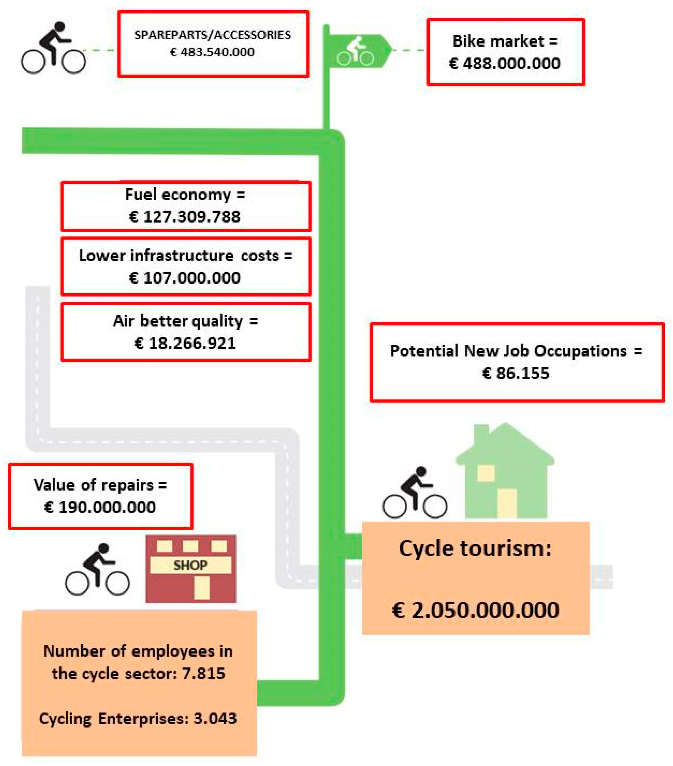
Figure 2 presents information on the cycling market in Italy, given by Legambiente in the second A Bi Ci report, which stated the amount of money produced by sustainable mobility and a growth perspective if public actors invest seriously in alternative means of transportation. The internal product bike (IPB), which is the turnover generated by “combined pedal movements”, is over 6.2 billion euros a year, but the actual number could be over 22 billion. Bike-friendly cities are growing, and there is increasing attention given to cycling, which stands in contrast to the widespread thought that Italy is falling behind the group of countries with the most cycling performed [
2].
Cycling tourism is a form of cycling, with variants such as taking the train with a bicycle or with tours organized by agencies that provide logistical support and luggage transport. It is a particularly inexpensive way of travelling, which goes beyond the usual standards and routes of mass tourism. The practitioners, called cyclists, are almost always united by a strong environmental sensitivity, a great passion for cycling as a mean of transportation and as a way of life, a lively curiosity for unknown places, and a great adaptability to unexpected situations.
3.1.2. Quality Function Deployment Methodology (QFD)
We first used six wh-questions of the QFD methodology to determine a list of characteristics that delineate a bicycle.
Who will use the product?
Adults aged between 18 and 70, mostly with financial opportunities
Adults who commute around the city and prefer not to use the car
When will the product be used?
Central hours of the day to avoid car traffic
Working days of the week
Daily, as a mean of transportation to go to work or to use in leisure time
Why will the product be used?
To reduce fuel consumption
To reduce time spent in traffic
For medium-length travel, to avoid traffic and reduce stress without missing out on the experience of owning a mean of transportation
What is the product for?
How do users use the product?
Like a normal bike, but with an electric motor
Combined with other modes of transportation, as the bike can be easily transported
Where do users use the product?
To sum up, the list of features is made up of the following traits: (1) equipped, (2) fast, (3) economical, (4) compact, (5) hybrid, (6) light, (7) safe, (8) autonomous, (9) versatile, (10) transportable, (11) stable, and (12) ecological. Due to the characteristics that we found, we were able to fill the relationship matrix, which gives us indications on what the most important features of the product are. The relative importance relationship matrix (
Table 1) is filled in as follows: 0 when the row is most important than column; 1 when both row and column are equally important; and 2 when the row is less important than column. After adding up the values on the column, we obtained a chart of the most important requirements that we believe customers desire (see
Table 1).
Below is a short explanation of how the numerical values were assigned: 0 is assigned if the prerequisite of the row is more crucial than the one of the column; 1 is assigned if the prerequisite of the row and the one of the column are both significant; and 2 is assigned if the requirement of the row is less important than the one of the column.
After the compilation of the table, all the numerical values of the columns were added, and the highest sums were highlighted. In our case, the characteristics that have the greatest value are compactness, lightness, versatility, and transportability. The requirements highlighted here are those that will have a greater importance in defining the design of the product.
In the same way, in the relationship matrix of dependence/independence (
Table 1), every unit has to be filled with a numerical value from 0 to 9 that define how much the characteristics of the rows are more or less dependent on the ones in the columns. We assign 0 if the prerequisite of the row is completely independent from the one of the column; 1 if the prerequisite of the row is not so dependent on the one of the column; 3 if the prerequisite of the row is very dependent on the one of the column; and 9 if the prerequisite of the row is completely dependent on the one of the column.
At the end of this analysis, we calculated the sum of the numeric values in each column of the table. In this way, we obtained a list of the most independent requirements of our project, i.e., equipped, economical, light, and stable (see
Table 2).
Considering the first four requirements of the matrix of relative importance and the first four of the second one, we determined a list of project characteristics. It was decided that the bike is to be a product rich in accessories and customization elements that do not affect the price, and the stability and safety of the bike is also of top concern. We intend for our electric bike to be versatile enough to adapt to medium-long distances without sacrificing compactness and therefore the fluidity of driving/pedaling.
3.1.3. Benchmarking
For the analysis of competitors and benchmarking, a distinction was made among the categories in order to be able to choose those most suitable for design. The product categories were divided into the following: mountain e-bikes (e-Mtb), city e-bikes (e-City), trekking e-bikes (e-Trekking), racing e-bikes (e-Strada), folding e-bikes (e-Folding), and cargo e-bikes (e-Cargo). Benchmarking, however, was only carried out on the e-City, e-Folding, and e-Cargo categories as the environmental analysis focuses mainly on urban activities.
E-bikes for the city are the first type of electric bikes that is often considered by consumers, as it is the segment that has had the greatest expansion and diffusion in the world. In Italy, we are witnessing a remarkable development for these bikes, and there are increasingly more users who choose to use city e-bikes to move around the city, go to work, and run errands. While electric folding bikes may not be as popular, they are constantly evolving because an increasingly large market is looking for the compactness and comfort of a bike that can fold but can also provide help with a pedal-assisted mechanism. Folding bikes can be closed and parked in a very small space. The last type we considered is cargo e-bikes. Already widely used in Northern Europe and now in strong expansion also in Italy, cargo e-bikes are designed to be robust, reliable, and above all capacious. Generally, there are two types: those with a front-loading space in front of the handlebars and those with a rear load, with luggage racks and storage compartments of great capacity.
With regard to the choice of the characteristics analyzed in benchmarking, more attention was paid to wheel size, battery life, engine position, battery position, operating voltage, charging time, on-board computer, weight, and price. The position of the engine on the anatomy of the bike also determines its characteristics. Currently there are 4 main types: (1) motor in the hub (it is a part of the wheel that allows for rotational movement and therefore the advancement of the bike itself), which consists essentially of two parts of the front or rear wheel; (2) an engine near or in place of the central movement box (called central motor); (3) an invisible motor hidden inside of external components or inside the column (it is the part of the frame that supports the central movement and the seat post); and (4) the engine near the front or rear tire (called clutch motor) [
3]. As far as the battery is concerned, the most important parameter for assessing its autonomy is its capacity, which is measured in watt hour (Wh). It indicates how many watts it can deliver in the time interval of one hour. Another important element to consider is the working voltage (measured in volts) of a battery that determines the maximum speed of rotation of the engine. An e-bike can generally run at 24, 36, or 48 V.
The control console of an electric bicycle can be considered as the part with its speaking and hearing functionalities, if we were to use an anatomical metaphor. Technological evolution has differentiated them into three families. The first is the analog console, equipped only with switches to adjust the assistance without providing any information. The second one is the digital console; its buttons and light indicators inform users about the engine status (whether it is running or not), the level of assistance selected, and the residual charge. In the most modern versions, it uses an LCD display and provides computer cycle functionality with GPS and cardio information. The latest family is the Bluetooth digital console; it includes all the advantages of the digital type but can also be connected to smartphones using its potential through dedicated apps.
From the comparison between the best and worst qualities among all those scored in
Table 3, we highlighted the so-called “tops” and “flop”. Between the number for tops and the number of flops, we calculated the difference and chose the highest score of them all. This score defines the minimum number of characteristics that must be innovated in the product, and in our case the degree of innovation is 6.
In order to reach innovation, we should obtain a product with ∆ ≥ 6, as determined by the characteristics analyzed in the matrix. We compared the customers’ requirements obtained from the relationship matrixes with the innovation characteristics of the product. In particular, the technical innovation characteristics were voted (from 0 to 10) by 100 people chosen among a different population (50% students; 30% professionals among 40 s to 55 s; 20% old people, mostly retired) a in order to satisfy the customers’ requirements; in this way, it was possible to have a list of technical characteristics that become the target for innovation. From the comparison of these requirements, we can elaborate the what/how matrix (
Table 4).
This matrix highlights the requirements that must be most innovative among all requirements; these top requirements are wheel dimension, weight, supported loads, and wheel number. Once the benchmarking and different matrices were calculated, we continued with the analysis. From this comparative analysis, we deduced the differential values between the positive and negative characteristics in the column of the various products.
The highest differential value will be the starting point to define the design drivers and the basic requirements of the new innovative electric bicycle. If we read the table of benchmarking on the lines, we could evaluate the characteristics of the ideal bike, which would have all the top values identified in the matrix. In our case, the ideal innovative electric bicycle should have wheels with a large but small diameter, so as to ensure the compactness and versatility of the product. It should have a battery life greater than 500 Wh and the rear engine position at the hub.
In this type of solution, the motor is integrated with the transmission and gives the feeling of a soft and effortless pedaling. The assistance is very high, so the muscle pedaling is minimal compared to the engine thrust: In fact, it is suitable for both urban routes and hiking. The ideal bike (
Table 5) should be a link between a lightweight folding and sturdy cargo bike with a load greater than 200 kg and three large and stable wheels.
Summing up the market analysis, we can say that the new bike will have to be autonomous and versatile as a city e-bike, stable and safe as a cargo e-bike, and compact as a folding e-bike.
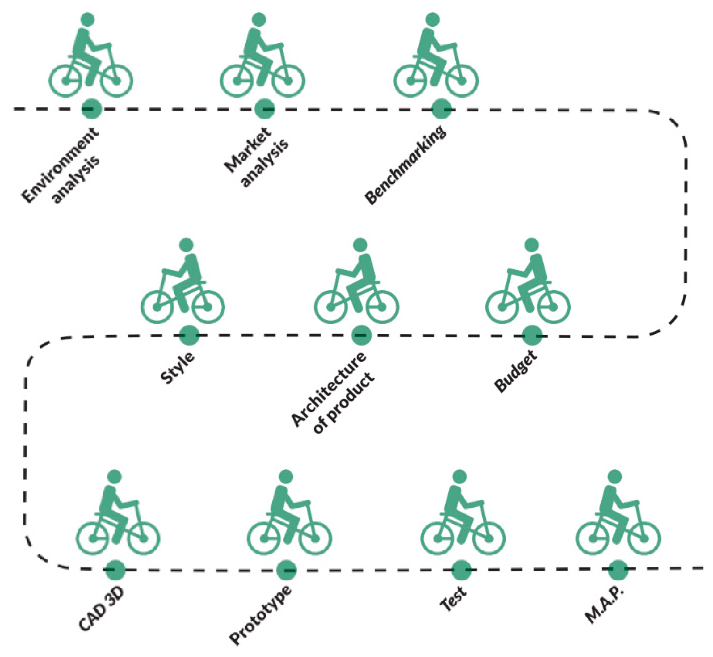
3.1.4. Activity Planning
Before starting the project, we defined a Gantt Plan in which we collected all the activities to be carried out. We set the work period from September to December, a period in which a team of three designers followed the so-called work breakdown structure (WBS). It includes the following macro-phases, also defined in the Gantt chart:
Environment analysis
Quality function deployment method
Benchmarking
First design review during the project planning
Budget
Product architecture
Style (stylistic design engineering; SDE)
Second design review during the project planning
CAD 2D and 3D
Prototyping and rendering of product
Testing
MAP
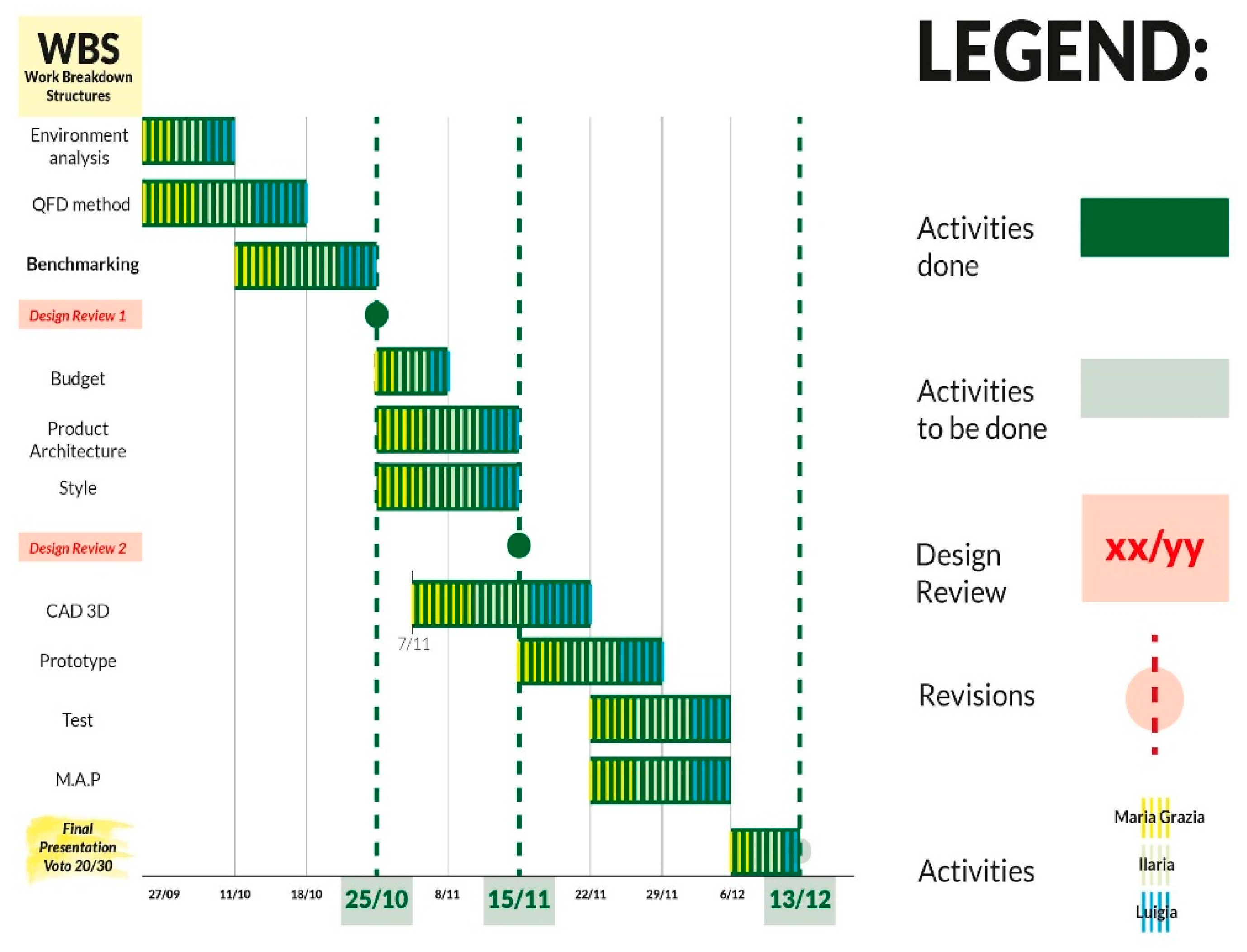
The Gantt Plan (
Figure 3) also establishes the time to be used to end each activity as well as which members of the team take care of which tasks. This ensures the efficiency of each designer and the respect of deadlines.
3.1.5. Budget: Research and Development Costs
The evaluation of the research and development budget was made on the basis of a make-or-buy matrix that divides the factory components to be purchased already in stock, and the components that need to be made. The items to buy are a leather saddle, handlebars, cuffs, disc brakes, wheels, drive system, engine, and battery, pedals, spotlight and tires. The elements to be realized are the aluminum frame and the leather cargo, as they are the most characterizing components of the project, and therefore they deserve extra attention in the design.
The frame is made of aluminum and is obtained by the deformation of tubular profiles, while the cargo is made of leather or leather with straps for closing. As for the calculation of the budget of the working hours of the staff, a team of three designers, two engineers, two technicians of technologies and processes, and two testers (one male and one female) were hired to work. The two testers are tasked to test the product for the evaluation of pedal assistance, driving comfort, and compactness of the vehicle on urban routes.
The product development path was divided into design, prototyping, and testing. All phases are based on three months of work in which the experts worked eight hours a day for five days a week. The budget evaluation led to the definition of €2847 for the prototype material and €149,020 for the R&D cost (
Table 6 and
Table 7).
3.1.6. Product Architecture
From our research on the bicycles that are already on the market, we were able to develop a product architecture that was suitable for our ideal bicycle. Following the IDeS method, we first defined the engine and battery position, and then other technical formal solutions.
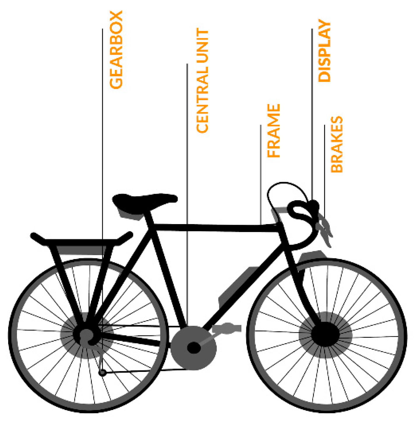
An e-bike consists of an electric motor, a battery, handlebar controls, a series of sensors, and an electronic control unit. The nature and arrangement of all these components is variable and determines the type of electric bicycle. The increase in weight of the medium compared to a motorcycle usually varies from a minimum of 3 kg to a maximum of 6 kg and requires a solid frame, an adequate braking system, a well-adjusted absorbers, and sturdy tires (
Figure 4) [
4,
5].
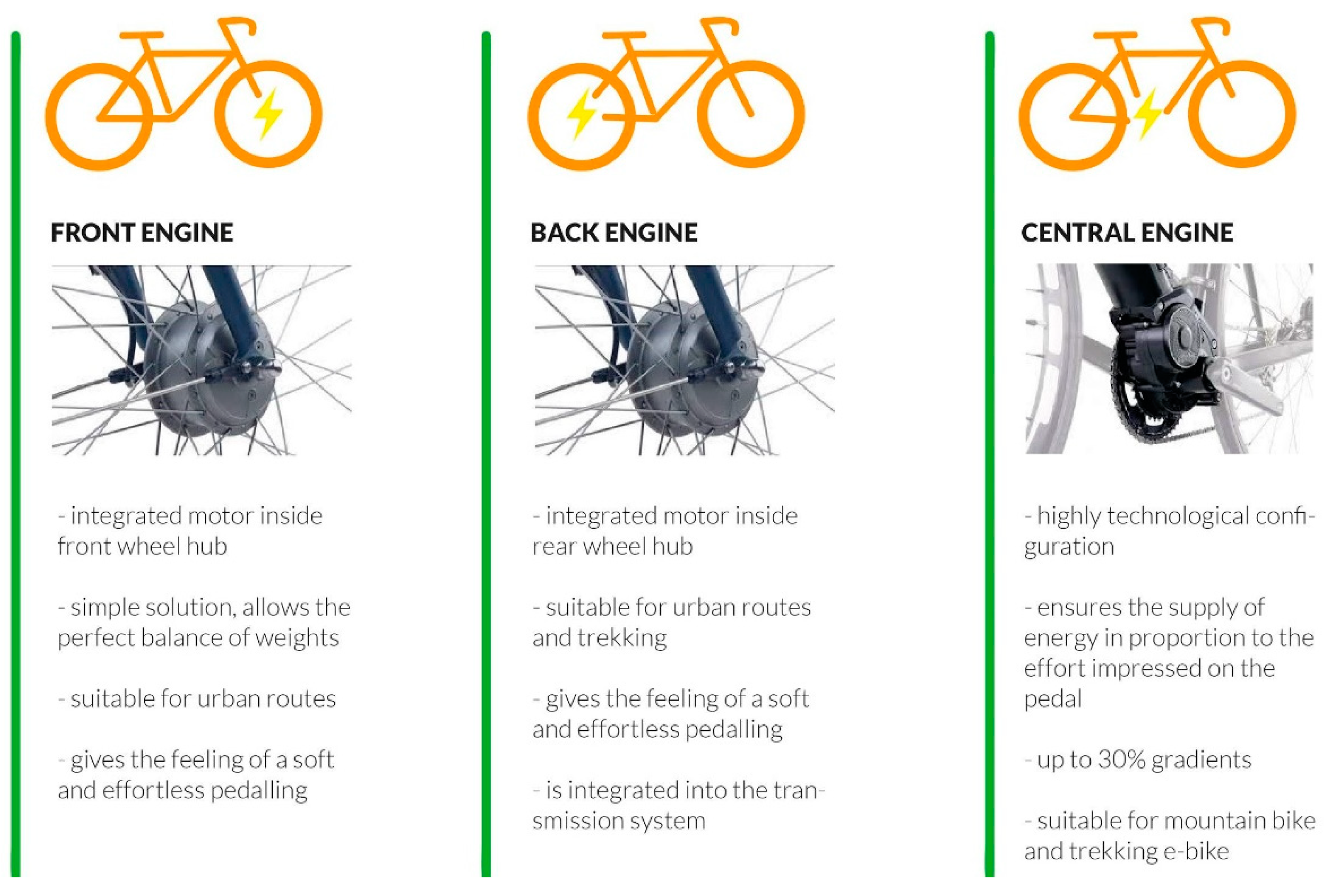
The engine can be immediately distinguished from the position on the e-bike, and currently there are three main types (
Figure 5):
engine in the hub of the front or rear wheel, known as engine to the hub or a hub motor;
engine under or in place of the center movement box, known as the central motor, also called a mid-drive motor;
motor in the vicinity of the front or rear tire, known as the roller or clutch engine, also called a roll drive motor or friction drive motor.
- 2.
Battery
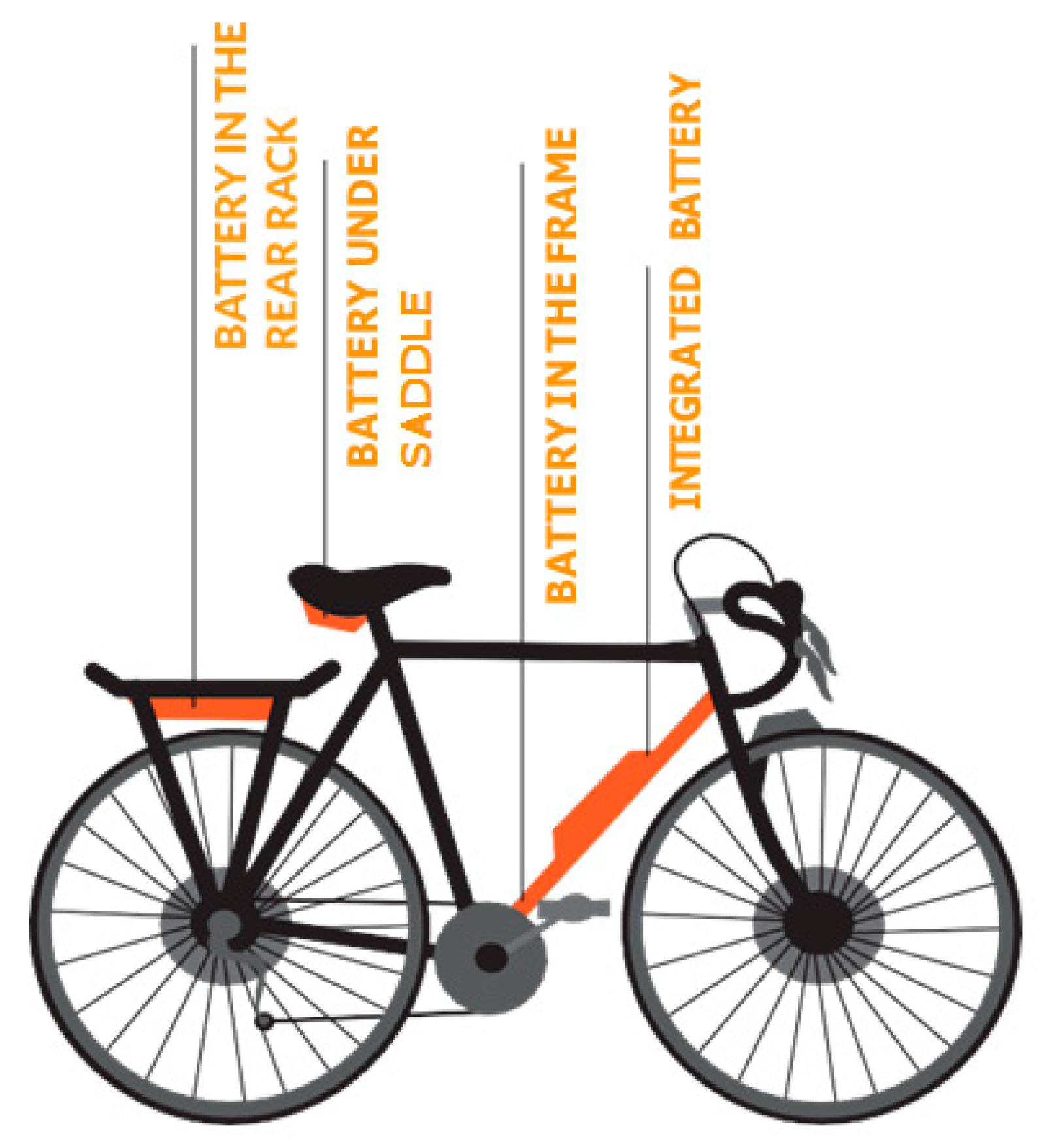
The battery is the heart of the e-bike, as this is what gives the bike its power. We can find it in different places of the bike, but the location in this case does not provide any information about its internal characteristics. In a nice casing, one can hide a low- or high-quality battery and vice versa. The following are possible cases of battery placement (
Figure 6) [
5]:
Battery is placed in the location normally reserved for a water bottle holder; the inside is a container integrated with graphics and frame lines to harmonize the aesthetics as much as possible. It is the most classic position, and sometimes it is hidden inside a fake canteen.
Battery is placed in the rear rack, inserted inside a housing that allows users to load weights on the luggage rack without burdening the battery itself.
Battery is placed under the saddle. It can be found in a rigid box or in a generally small bag.
Battery is placed on the handlebars. This is the rarest case because if it is heavy it will seriously affect the maneuverability of the bike.
Battery is integrated into the chassis. In this case, the battery is located inside the chassis or in the middle of the chassis as a carrier.
Battery is in the backpack. The battery is inserted in a special pocket of the backpack that keeps it as close as possible to the back to minimize the load on the shoulders.
- 3.
Architecture of the new product
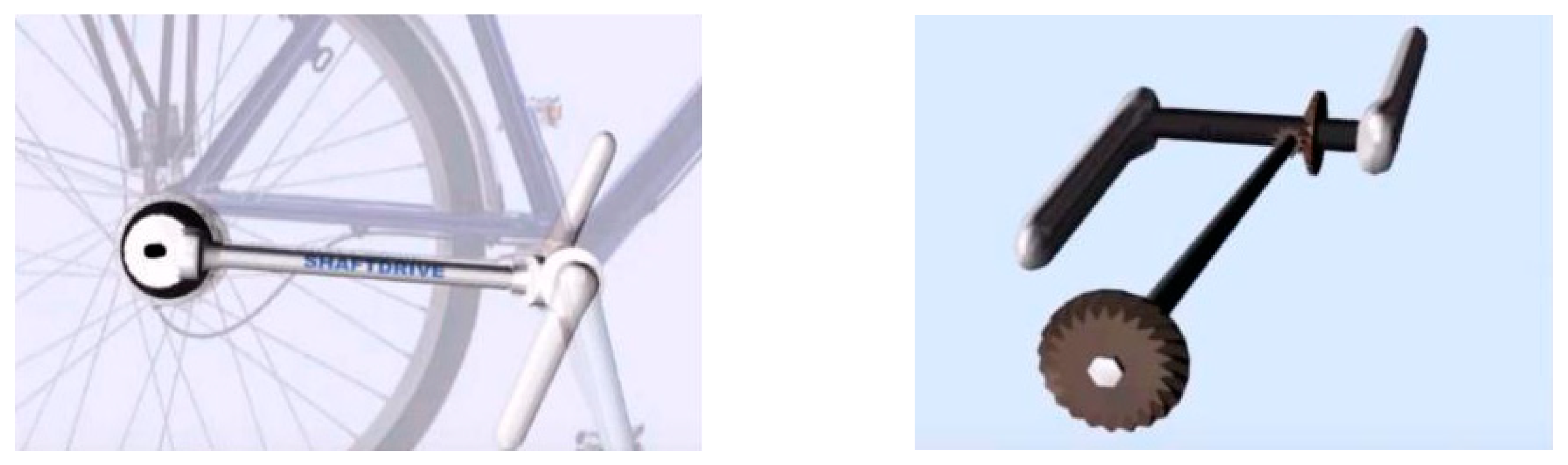
The transmission system is entrusted to the drivetrain, which represents the most significant innovation in bike transmissions in recent years, if not decades. With the elimination of the chain, gearbox, and derailleur, this system is based on a gimbal, i.e., a shaft that transmits the pedal force from the crown (single) to the sprockets, where there are 13 in all. The cardan uses bearings to transfer the power, which happens with a reduction of 49% of the friction compared to the traditional system with sprockets, crowns, and chain [
6].
This solution, used for the first time by Euro-bike, allows for 13 different ratios, obtained by moving the rear gear of the cardan on the various sprockets of the cassette. As far as the transmission concerned, the cardan is the optimal solution when the engine is arranged lengthwise in the frame. Specifically, the cardanic transmission “takes” the motion from the crankshaft and transfers it directly to the rear wheel. For this reason, it integrates perfectly with the motor to the hub. The system requires a specific frame that can accommodate the gimbal, and the hub does not require any special arrangements at all and is integrated into the transmission system.
The choice of engine position derives from the study that was done using the QFD method. Among the bikes that achieved a higher number of tops in benchmarking, there is the Moop Bike Hybrid city and the Pedego stretch cargo dual drive. Both products have a hub engine; in fact, they are high-performing bikes. Using the what/how matrix we identified the profile of the ideal bike, which has an engine at the rear hub, not a central engine.
According to the design of the supporting structure, it was essential to consider the position of the battery. Given the product architecture of our bike and the shape of the frame, we opted for the battery in the saddle, as this is space-saving and less invasive.
3.1.7. Stylistic Design Engineering (SDE)
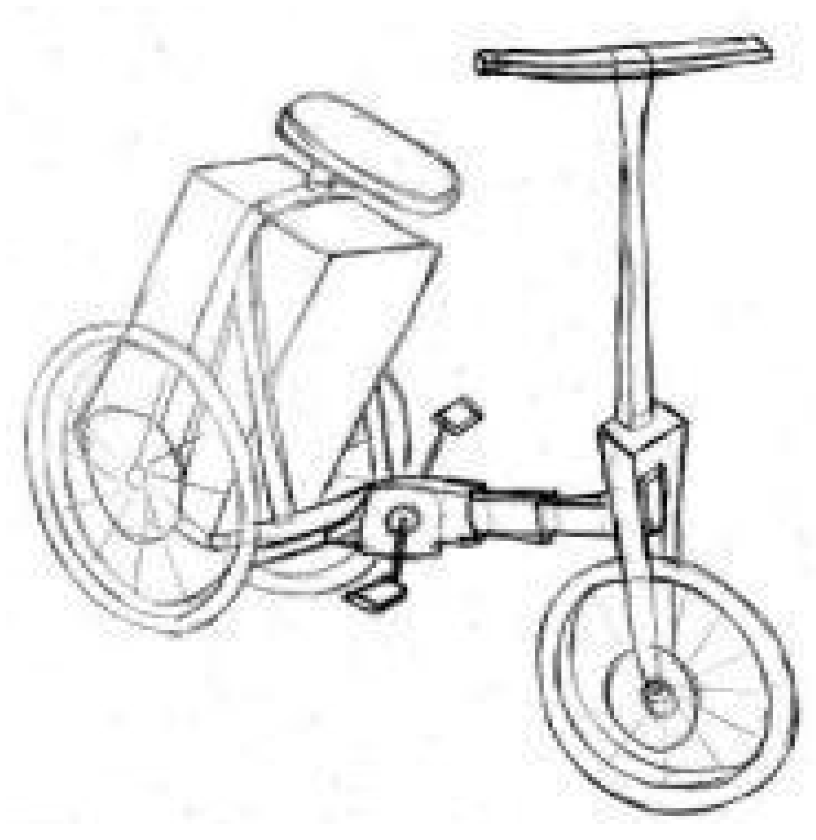
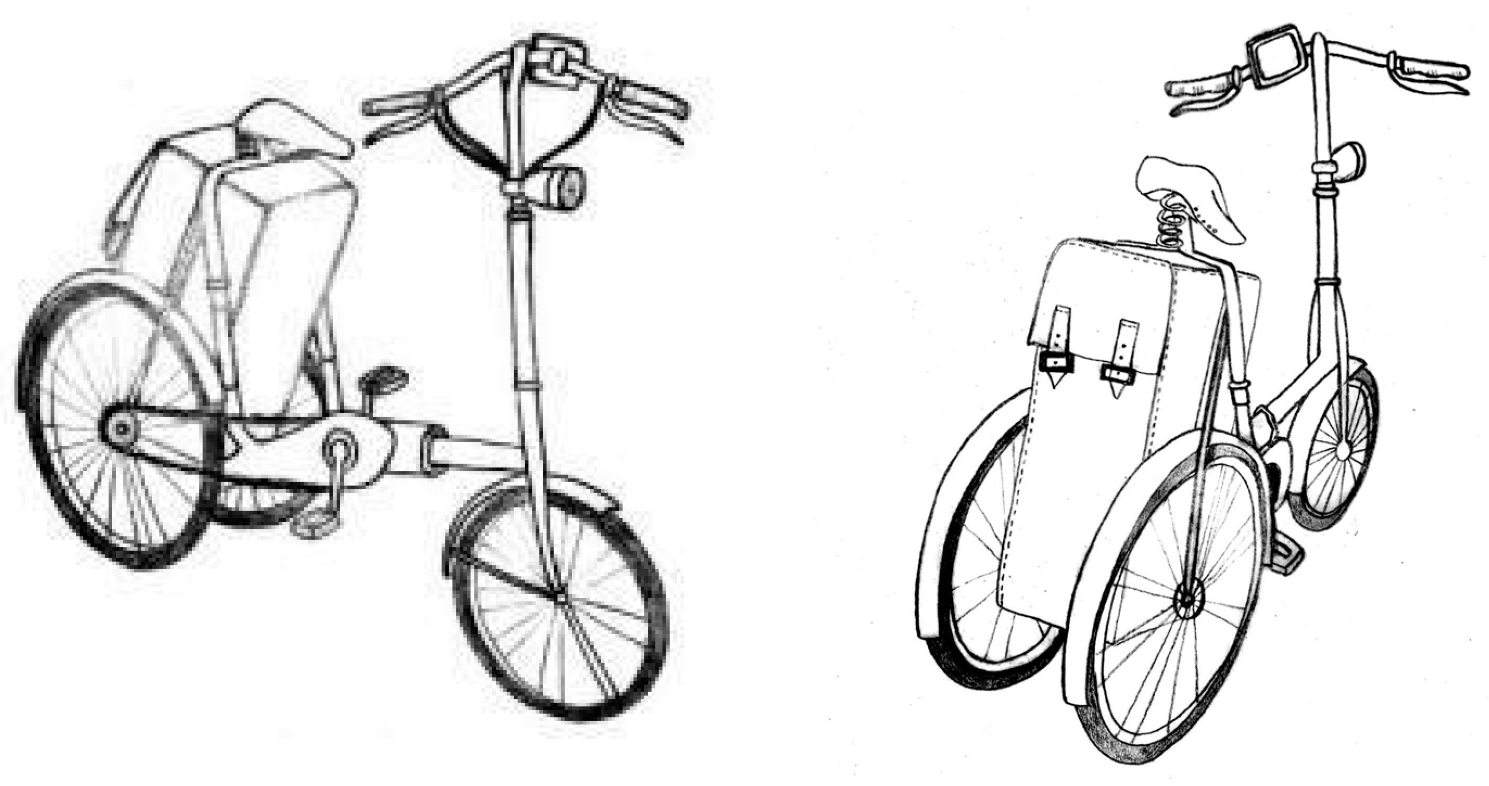
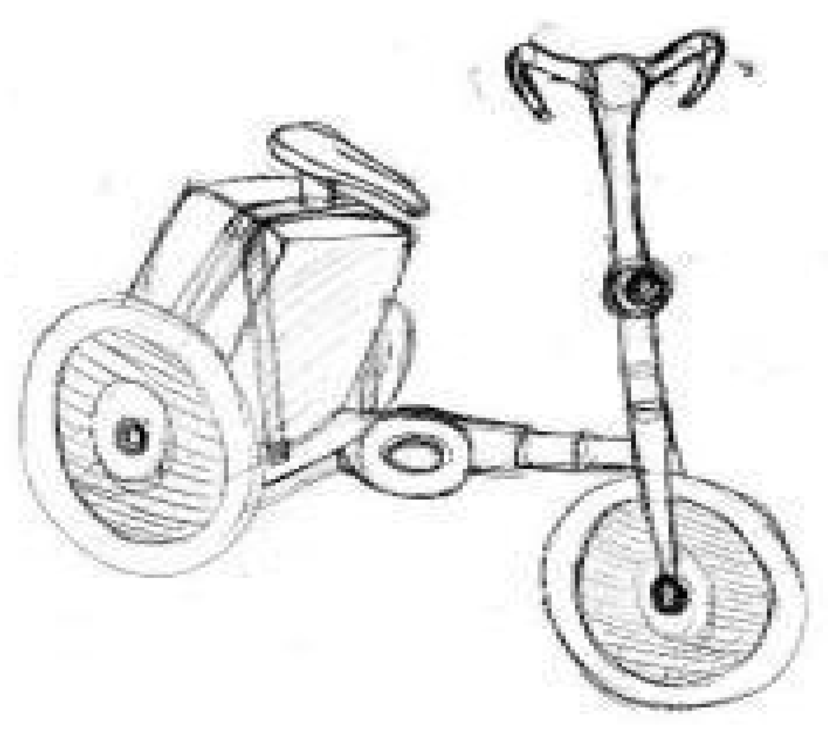
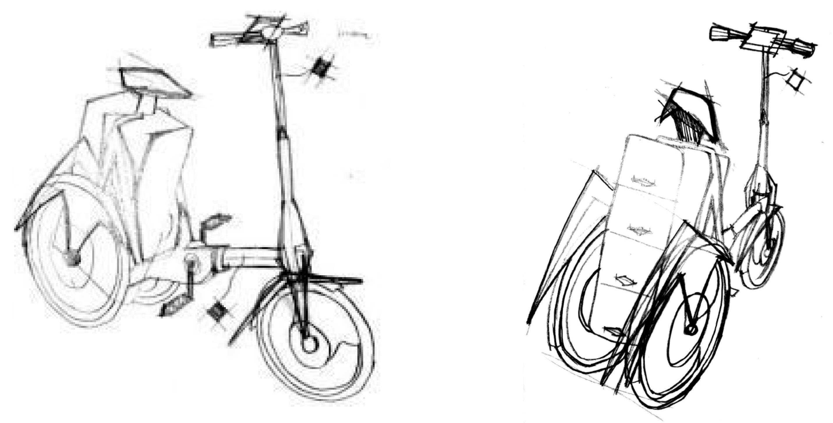
We analyzed different types of styles and made sketches for each of them. In this way, we could choose the most suitable design among several: (1) natural (
Figure 7), characterized by organic lines but solid at the same time; (2) retro (
Figure 8), which recalls the classic bicycles of the boom years, with highly vintage accessories and a leather trunk, as if it were a suitcase; (3) advanced (
Figure 9), which is characterized by futuristic lines, and the whole is reduced to the use of bends both in the rods and in the circular joints; and (4) stone (
Figure 10), a more aggressive style that relies on the exaggeration of the lines, to the point where they give origin to appendices of the structure, as in the case of the very accentuated fender.
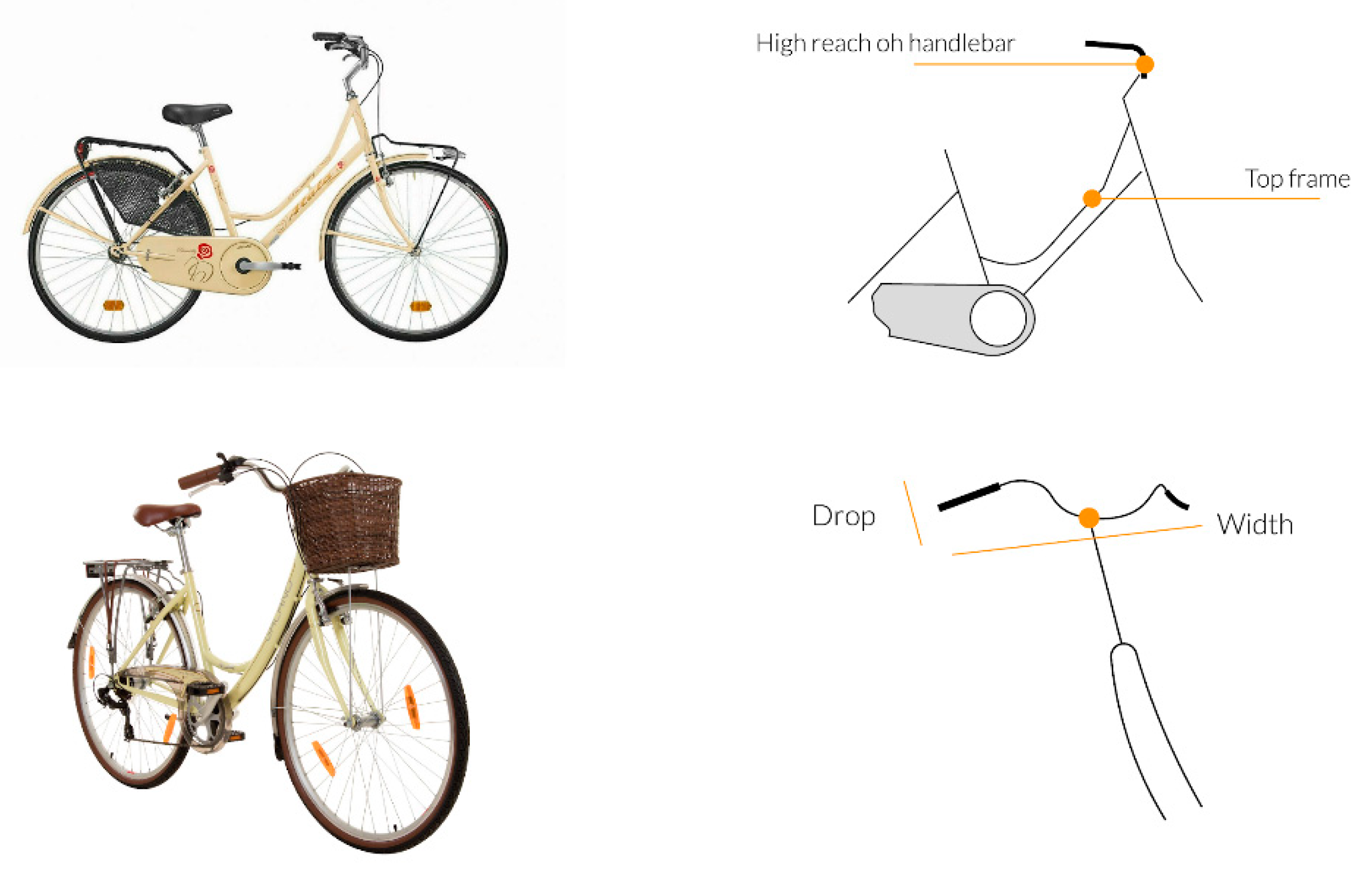
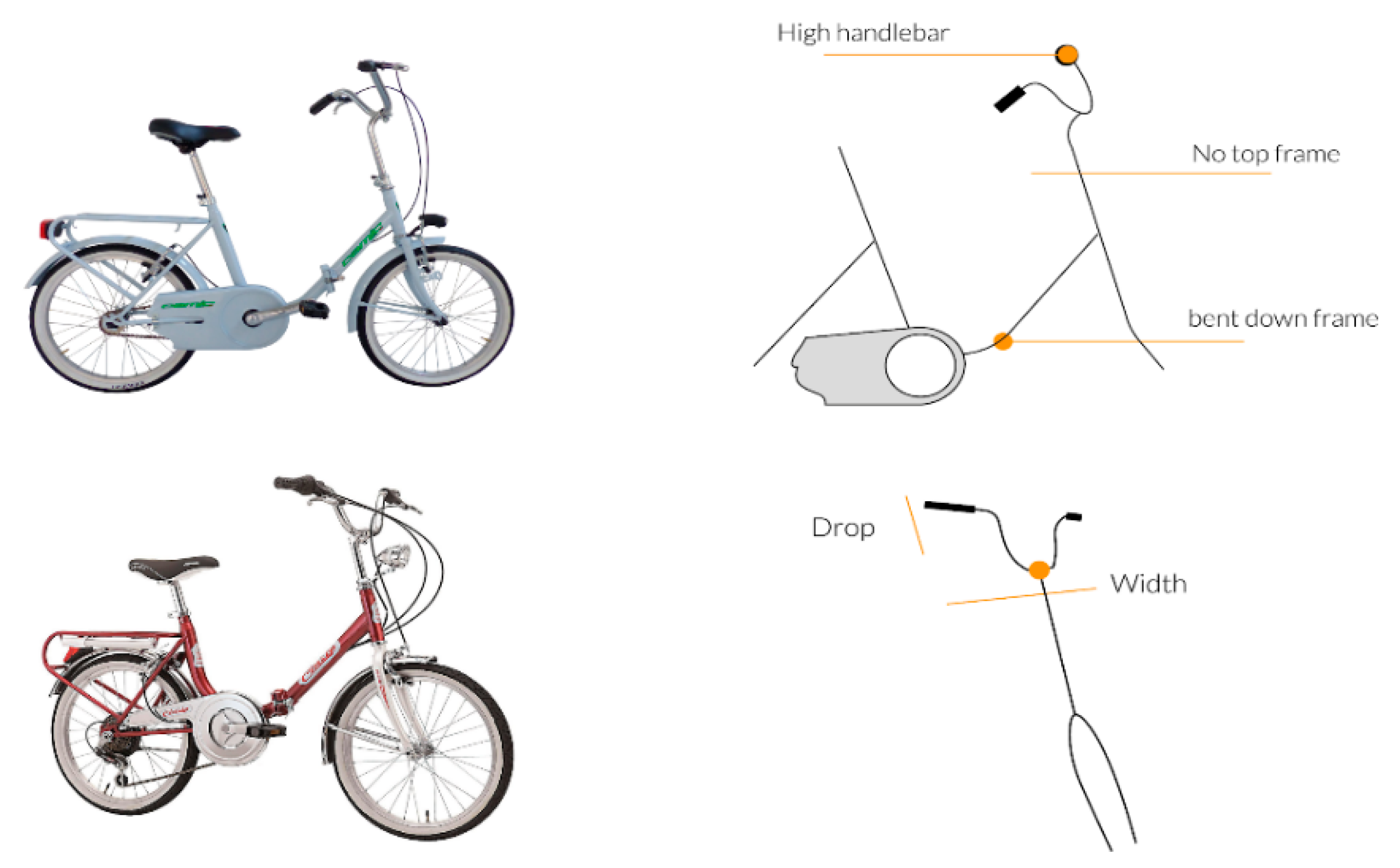
In light of the sketches, we carried out a reflection on the archetypes of the product “bicycle”. We looked in the literature for examples that gave an iconic and interesting image of the bike, and in the end we decided to analyze two fundamental models, i.e., the Atala model Piccadilly and the Graziella model Cinzia (
Figure 11 and
Figure 12).
3.2. Product Improvement
In product development, we applied all the theory that we carried out in the previous phases and moved onto practice. This is how we defined the technical drawings and the more engineering aspects of our bicycle.
3.2.1. Design Engineering
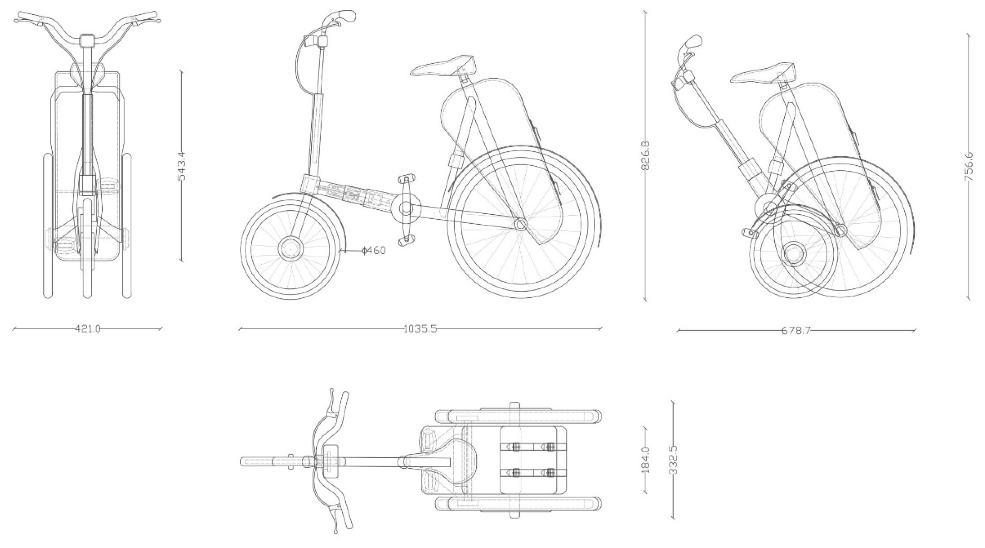
As for dimensions, the bike has a height between 756 and 826 mm because of the gas spring that secures the folding bike. Because of the gas spring used, there is a range of adjustments for the length of the frame. The aluminum frame has a dimension between 687 and 1035 mm, based on the activity carried out by the user. In this phase, 2D drawings (i.e., orthogonal projections) of the bike were made (
Figure 13).
Subsequently, the following definitive materials were chosen:
As regards the transmission, we chose not to insert the chain kit. Instead, a cardanic transmission was chosen (
Figure 14), where the transfer of motion of the cardan joint occurs due to the incidence in a point of two rotation axes. The decision is due to a number of advantages brought about by this type of transmission including minimal maintenance, easy cleaning, no noise, smaller footprint, and more pleasing aesthetics [
7,
8,
9,
10,
11].
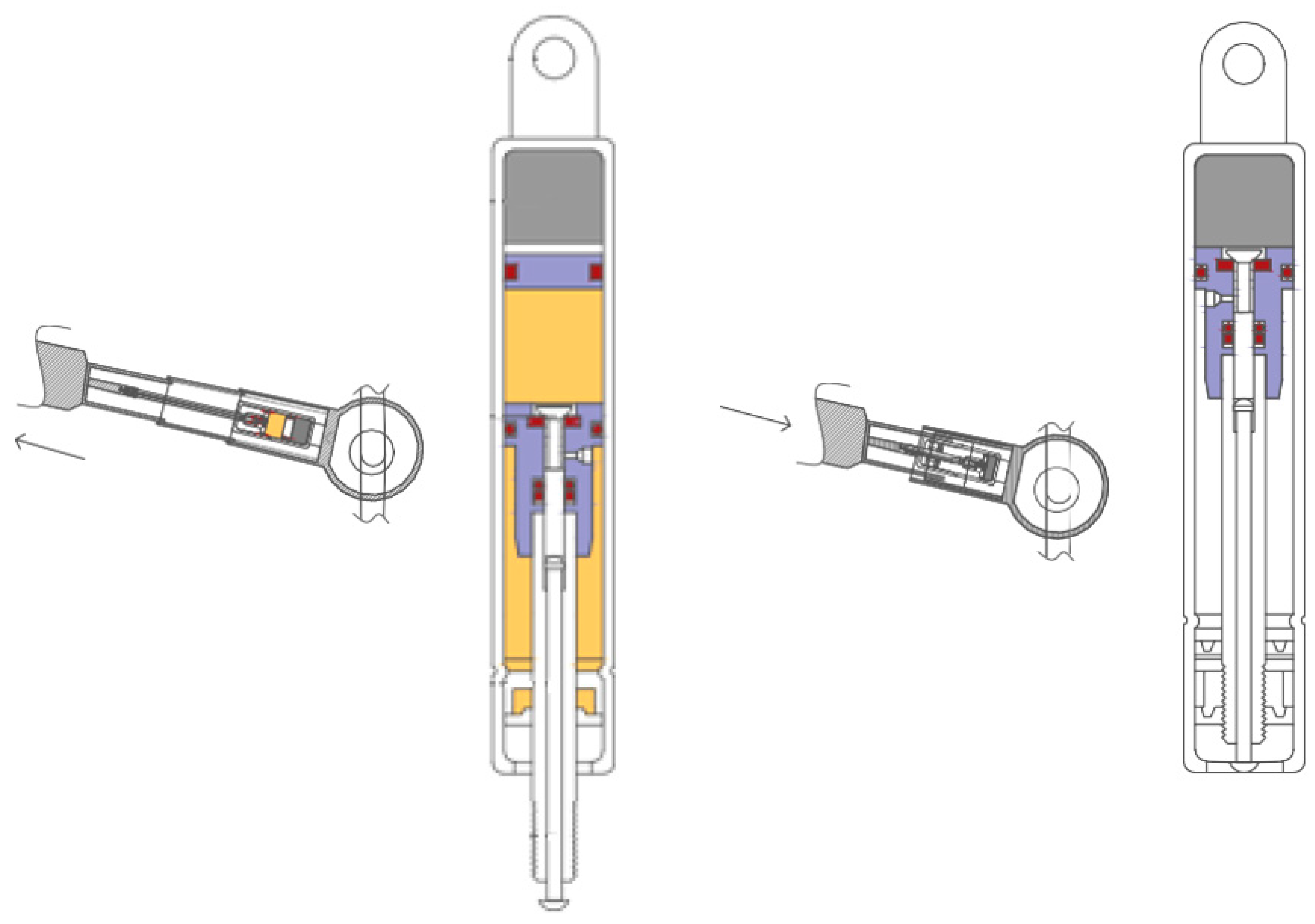
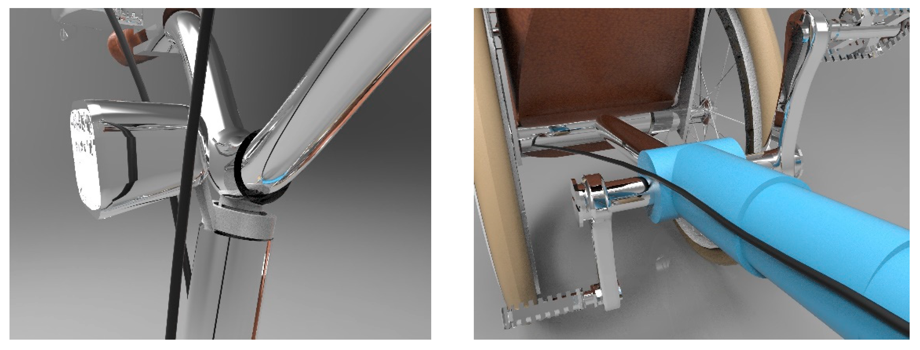
Concerning the range of the length of the bike, the main innovation of the product is the telescopic frame. To solve the problem of handling and folding the bike, we used a gas piston to reduce the dimensions and to close the bike as a trolley.
We opted for this system because it is a solution that allows the user to close the bike without lowering it. Other mechanical systems work only if the user gets off the bike and lowers it to close the levers of the frame. With a gas spring, the bike can also be closed with the user staying in the saddle and pulling the bike towards them.
The gas spring is composed of a steel cylinder containing pressurized gas (nitrogen) and a stem that flows into the cylinder itself through a sealing ring. The pressurized gas from the stem entry returns a thrust, behaving like a spring (
Figure 15).
Compared to traditional mechanical springs (whether helical, cup, or rubber), the gas springs have an almost flat force curve, even for very long runs. They are used in all those cases where it is necessary to obtain a thrust proportionate to the weight to be lifted or moved, or to counterbalance the lifting of mobile and heavy equipment.
The most common applications are visible on car doors, on industrial machinery protection cases, on furniture doors, on medical and fitness equipment, on tents and motorized covers, on attic skylight windows with an opening, and inside the supermarket stalls and butchers. A certain amount of oil is introduced in the gas spring cylinder; in addition to ensuring the lubrication of the seals and to interposing between the piston and its guide, the oil performs a slowing action in the extension phase of the stem, providing a smoother movement without startling.
The thrust of a gas spring is determined by the pressure that the nitrogen, placed in the cylindrical body, exerts on the section of the stem. It is possible to assemble stems of more or less sections with bodies of appropriate volume, to act on the gas inlet pressure, to adjust the passages present on the piston or to add more oil; in addition to the desired forces, various operating configurations of the gas spring can be obtained so as to satisfy the wide needs of the users.
A gas spring was chosen in order to have a more intuitive usability and a simpler interaction for the user. In fact, to close the bicycle it is not necessary to carry out many movements, such as bending or unscrewing bolts. The only necessary action is to push the handlebars, and the bicycle will close naturally. In order to achieve this, when assembling the spring in the frame, it is calibrated to respond to a certain Newton range [
12,
13,
14,
15,
16].
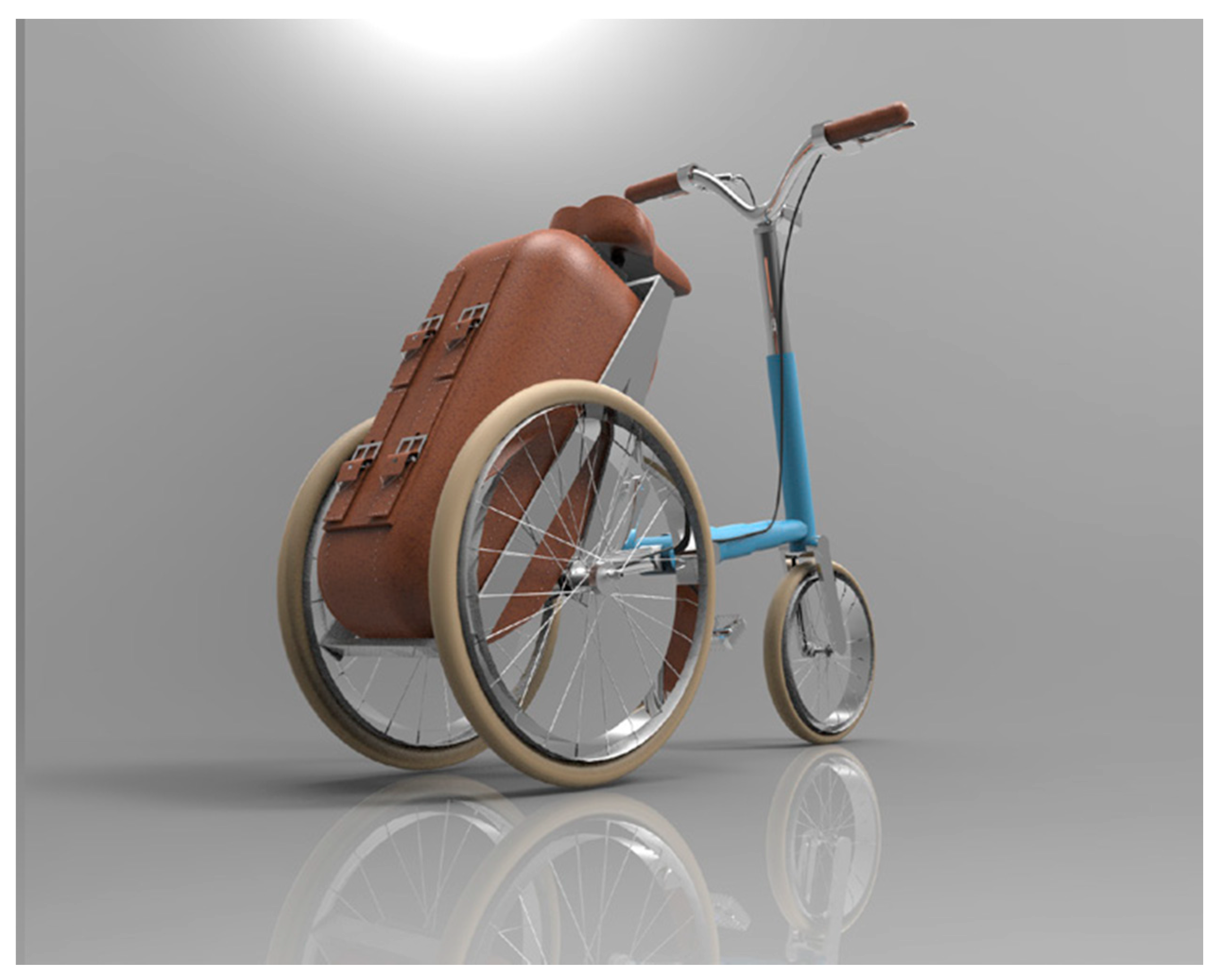
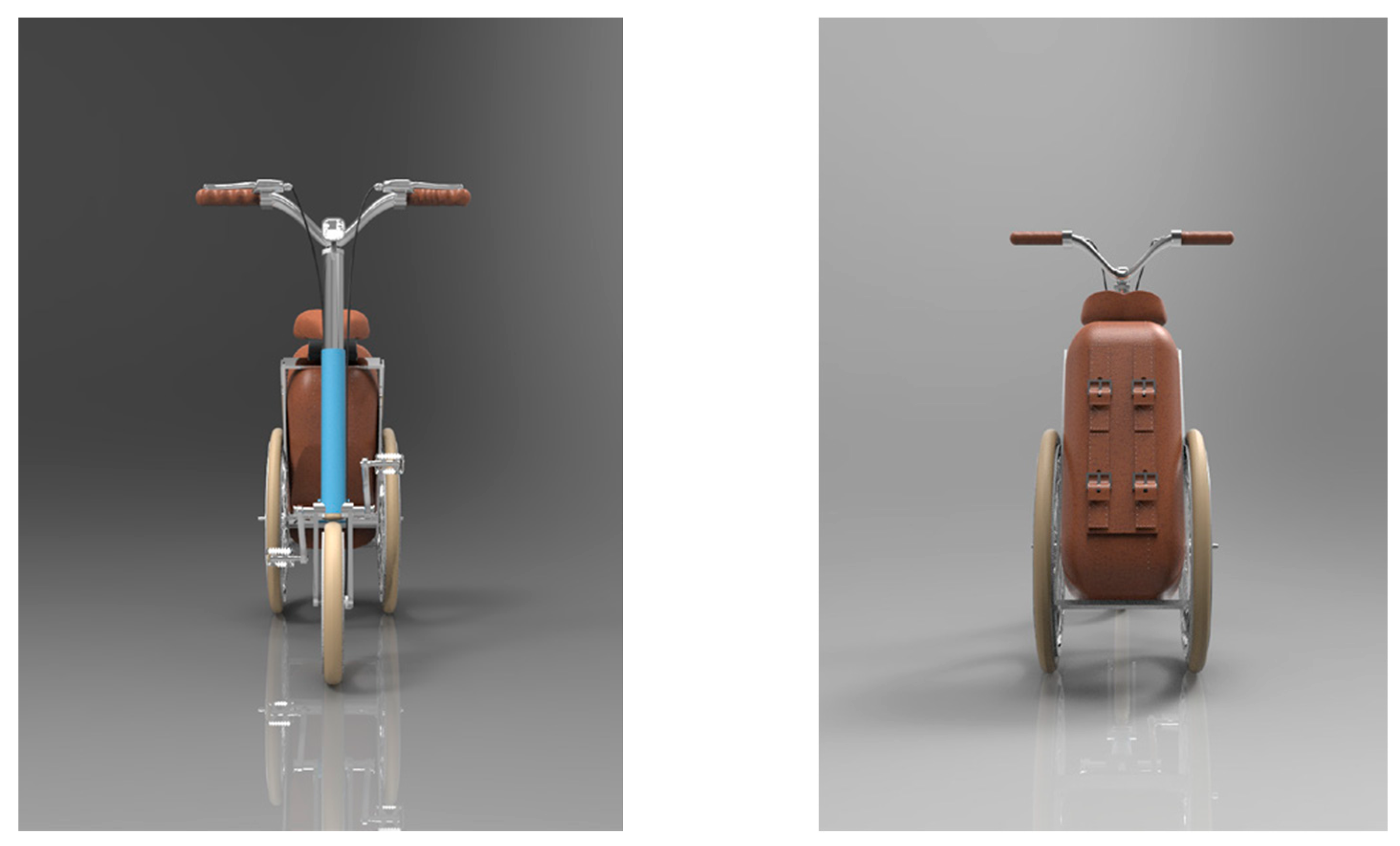
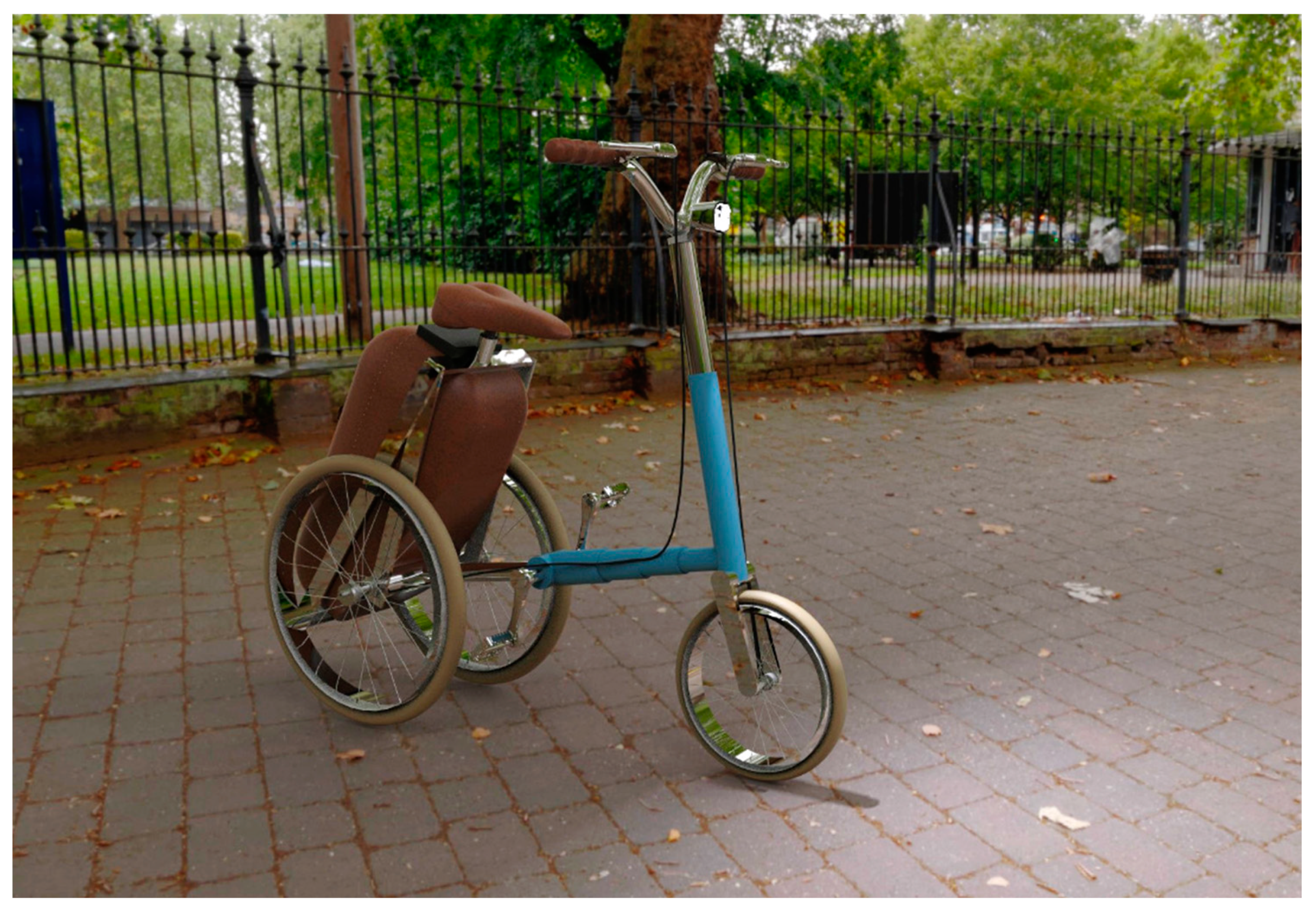
3.2.2. Prototyping and Rendering of Product
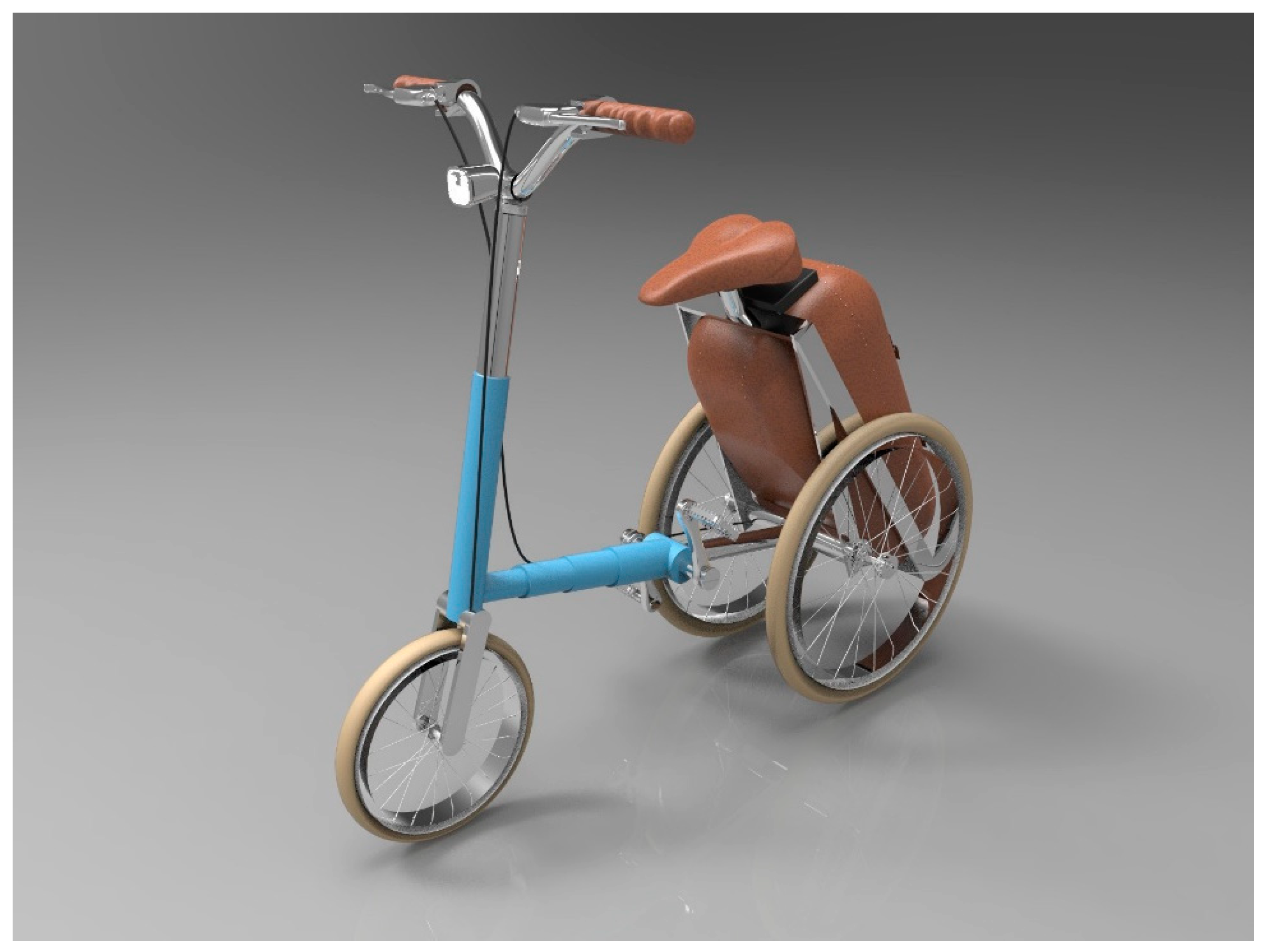
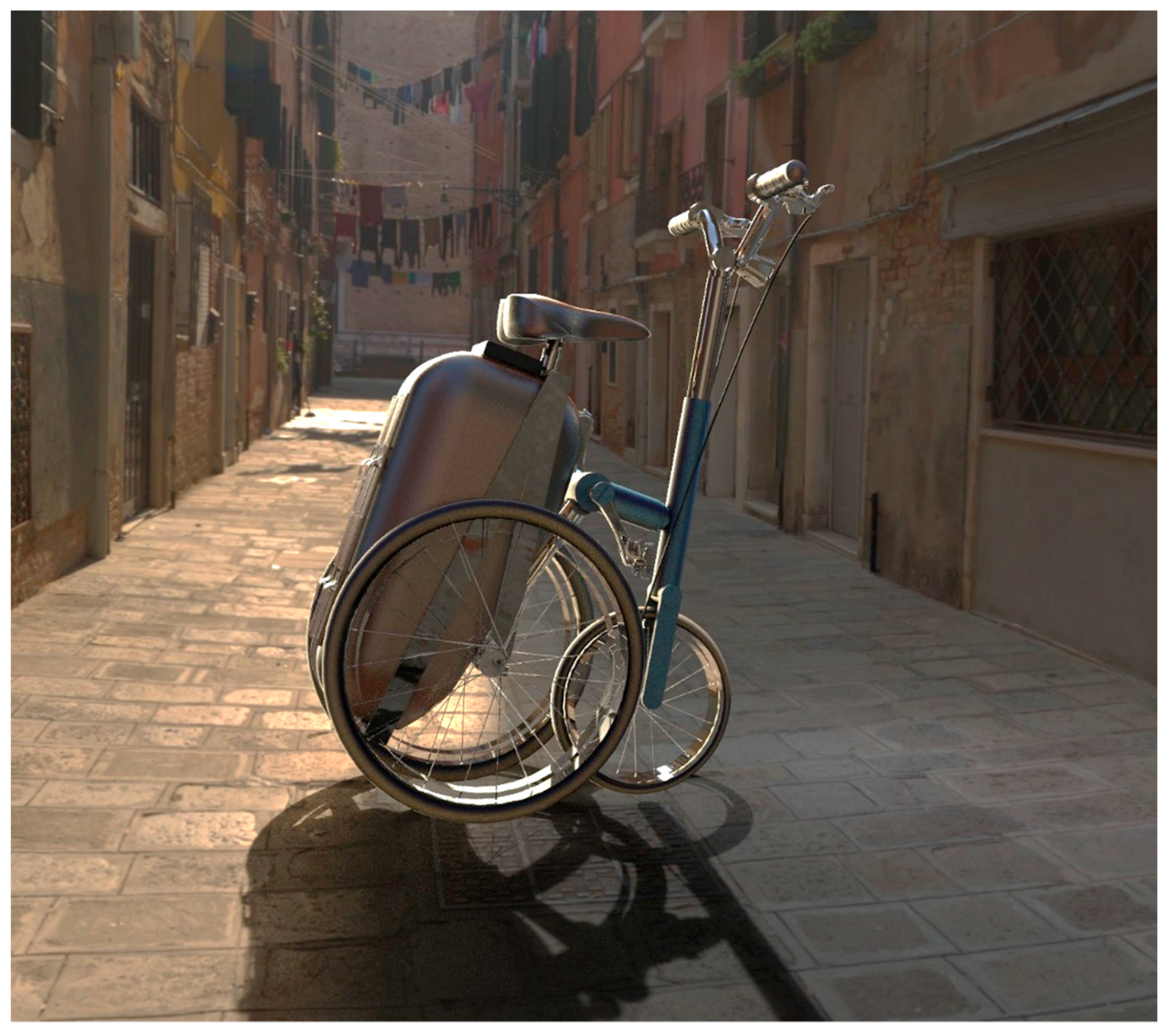
In order to make a 3D CAD rendering, we used a software called Rhinoceros, a NURBS surface modeler. Once we realized the three-dimensional model, we applied the correct textures and materials to have a simulation of the real product through rendering technology (
Figure 16,
Figure 17,
Figure 18,
Figure 19,
Figure 20 and
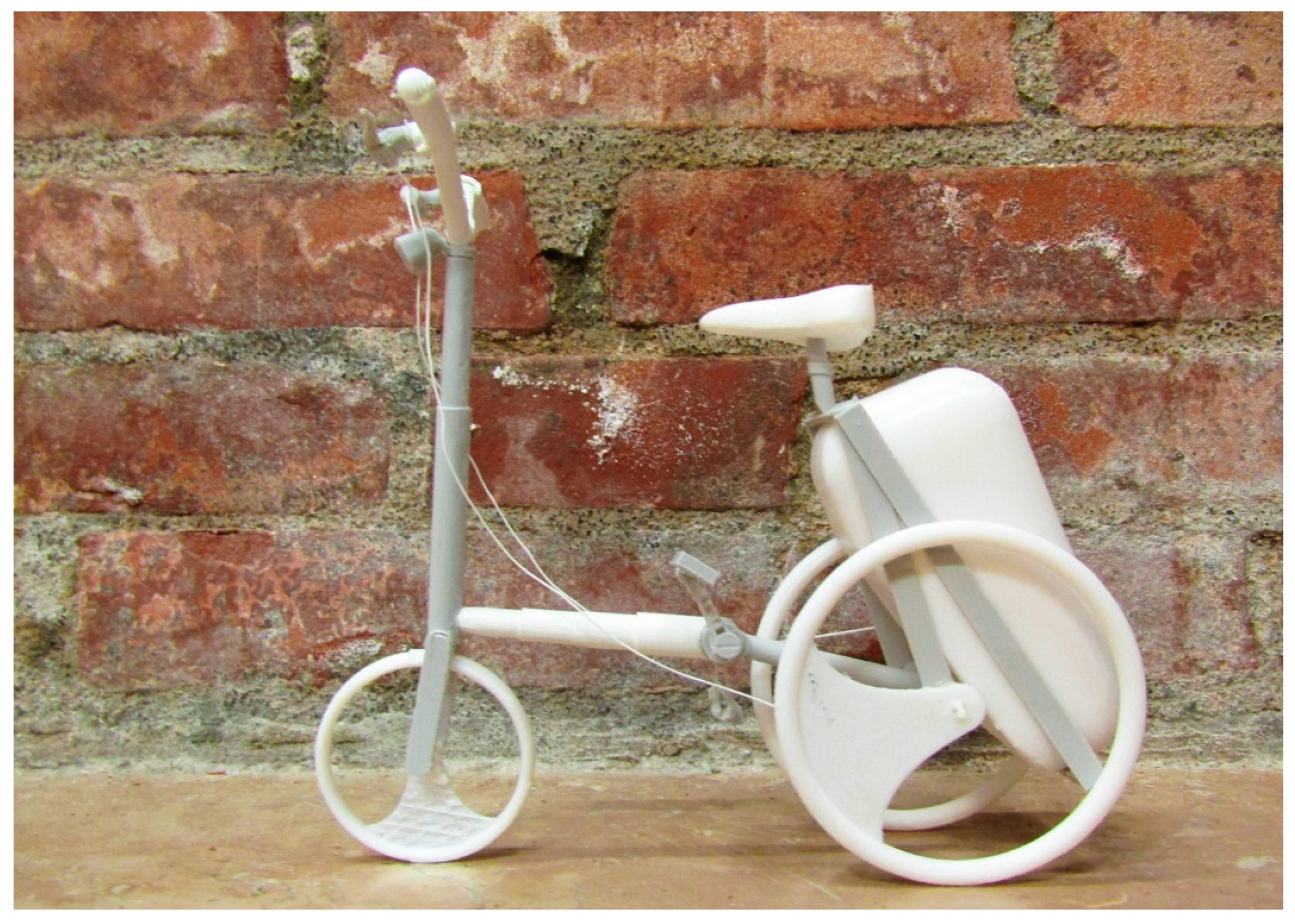
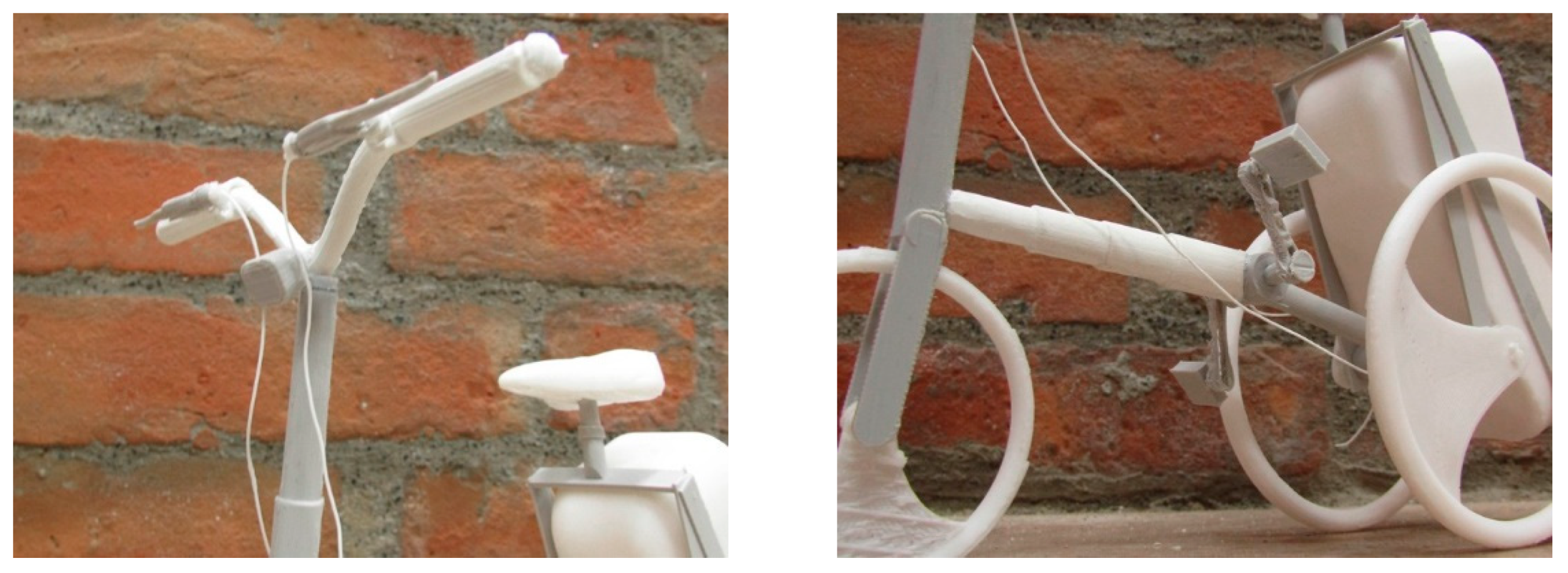
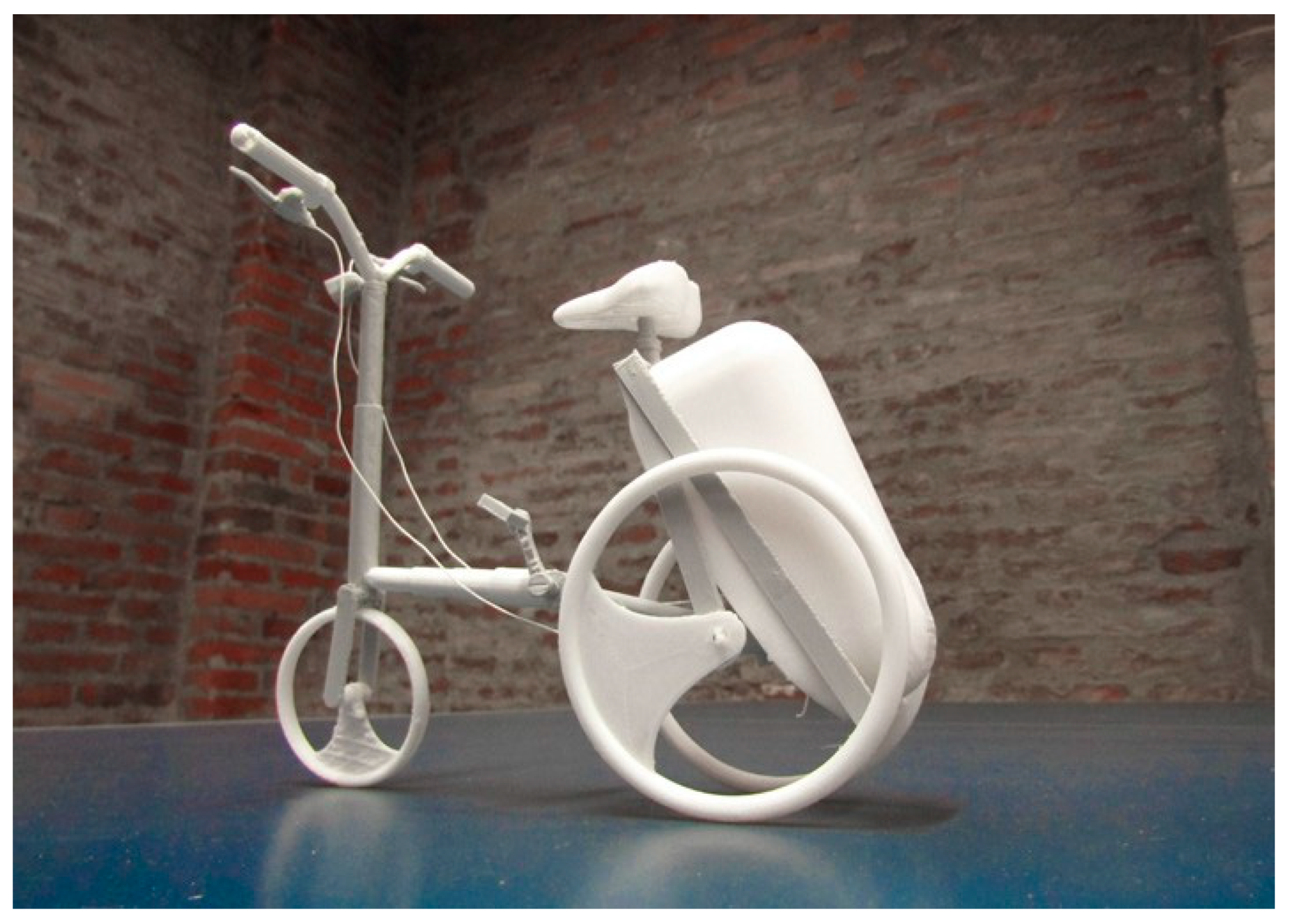
Figure 21). Finally, in order to verify the product model, we created a prototype in scale 1:5 using 3D printing technology (
Figure 22,
Figure 23 and
Figure 24).
3.2.3. Testing
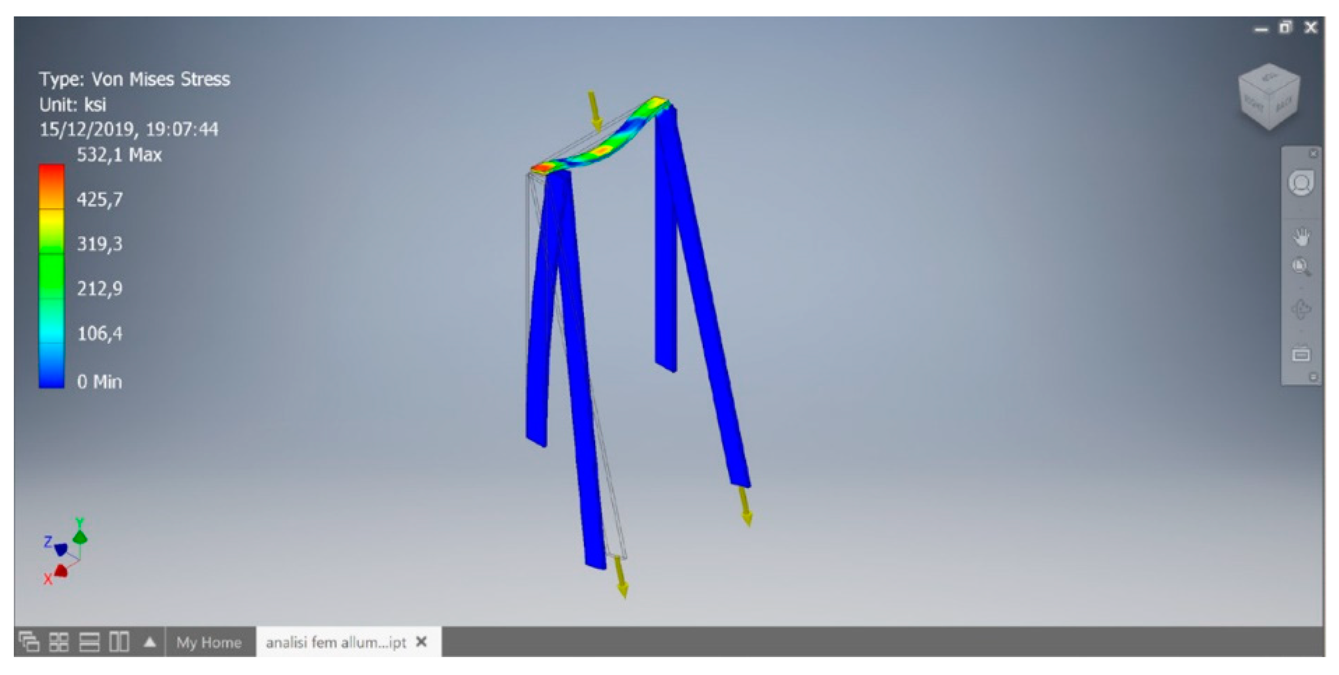
Using the solid modelling program Inventor, the frame was redesigned to study the static condition and loads applied. On the upper part of the frame, a force equal to three times the estimated load of an average person (90 kg) was applied to the saddle, and so the structure was studied with 270 kg of load. In addition, the stress resulting from the leather cargo, which has a capacity of approximately 58 L, was added [
17,
18,
19,
20].
Constraints on structure and materials were then defined, which in our case is anodized aluminum. Once the calculation program was run, it emerged that the stress was exaggerated with respect to the material and the assumed dimensions; in fact, the deformation was a beam with an axial applied load. One possible solution to the problem is to change the assigned material and sizes. As a matter of fact, by assigning the stainless steel and changing the size of the shaft to 1.75 cm, the deformation is much lower, and at the extremes, the stress is less concentrated (
Figure 25).


 ,
, 


