Abstract
In a growing number of battery-driven applications the need of removing any position and speed transducer is taking over due to space, cost and mechanical reliability constraints, further than making the installation easier as requiring less wiring. This paper presents the development of a sensorless algorithm capable of running an Interior Permanent Magnet Synchronous Machine (IPMSM), assuring constant torque production in the whole speed range, form standstill to high speeds. This is achieved with an hybrid method: at standstill and very low speeds the saliency of the IPM is exploited through an High Frequency Signal Injection (HFSI), which assures a robust estimation of the rotor position. At medium to high speeds an advanced V-I estimator is adopted in order to enhance the motor performances. The developed algorithm comes out of being highly scalable as it requires very little tuning, resulting in a multi-purpose application which can be employed with any motor size.
1. Introduction
The majority of industrial applications that involve motion is nowadays achieved with electrical machines, which make use of electro-magnetic effects to generate high density power with little losses. Besides, due to pollution constraints, also electric traction applications [1] are taking over the research activities and attracting big attention from companies from different fields. Considering synchronous motor, two macrocategories exist: those with the Permanent Magnets (PM) mounted on the rotor surface (Surface Permanent Magnet Synchronous Machines—SPMSM) and those with PM buried inside it (Interior Permanent Magnet Synchronous Machines—IPMSM) [2,3]. The former requires an high number of magnets for construction, while the latter only need a limited number of magnets [4]. This reduction in the number of employed magnets does not represent a drawback in terms of output torque, as Interior Permanent Magnets motors (IPM) can also count on the reluctance torque produced by the rotor anisotropy, generated by the inductance difference on the rotor axes. Recently, due to space, cost, hardware reliability constraints and simplicity in installation there is a trend of avoiding the usage of position and speed transducers. Anyway modern control methods operate into a d-q reference frame and cannot work without the position information needed to perform Park transformations; this paper will employ a Maximum Torque Per Ampere (MTPA) control which, given a torque reference, outputs two current references for the d and q axes, calculated basing on the solution of an optimization problem. Furthermore, a speed feedback is required in a wide range of applications. A solution to this demanding request is represented by the development of sensorless controls, which only require the knowledge of the motor drive output voltages and currents. Concerning medium and high speed operating points a variety of sensorless techniques have been developed in literature, from full-order model based observers to reduced-order V-I estimators. In [5] a complete observer has been developed, while in [6] the same observer has been improved using sliding surfaces. In [7,8] an alternative approach based on the Extended Kalman filter has been proposed to account for non-linear dynamics and it is proven to minimize the estimation error variance. Those works are extremely precise and reach a very good level of accuracy, but have the need of elaborating a lot of data in real time, this makes their implementation difficult on low-cost industrial microprocessors with limited calculation power, further than being very specific for the application they are developed for. For this reason many authors have proposed different improvements for classical reduced-order V-I estimators to decrease the computational complexity without worsen the estimation accuracy. The innovation consists in the introduction of a corrective feedback, evaluated comparing real and estimated currents [9] or magnetic fluxes [10]. In this way the V-I estimator is able to compensate the integration drifts and allows a better noise rejection. The mentioned techniques rely on the presence of back-EMF and are therefore feasible of being applied to any kind of electrical machine. However, since back-EMF effects are negligible at standstill and low speed, this technique is typically used only for medium-high speed. To derive sensorless techniques for standstill and low speed, different strategies have to be implemented. Thanks to the mentioned anisotropy, IPMSM are feasible for the implementation of techniques to precisely estimate the rotor position also at standstill and can therefore undergo a wide-speed range sensorless control capable of a constant torque production. Those techniques are based either on the modification of the normal PWM sequence required for driving the motor or on the injection of additional electrical signals from which information can be drawn. The former have their maximum expression in the Indirect Flux detection by Online Reactance Measurement (INFORM) method [11,12], which is very precise but requires a sophisticated high performance hardware due to the need of real-time differentiation and high sampling frequency to allow the sampling of the phase currents in the whole PWM impulse. High Frequency signal Injection (HFSI) techniques on the contrary can work on multi-purpose industrial hardware, causing their wide development. Among these techniques the most widespread are the so-called rotating injection, which are implemented in fixed stator frame, and pulsating injection, performed onto estimated rotor axis. A comparison between those techniques has been developed in [13,14,15], in which authors have analyzed the injection principles and the effects of non-ideal physical attributes on the mentioned methods. An additional distinction can be performed considering the kind of injected signal: a voltage injection can be performed as well as a current injection. Differences between the injection of different signals are reported in [16] where a voltage injection is shown to be preferable since it avoid further complication in the control scheme algorithm. On the contrary current injection requires a precise regulation of the injected signal which is pretty difficult to be performed and implies a precise tuning of the algorithm.The focus of the presented paper is to study a scalable sensorless control for a wide-speed range. In this work a hybrid technique which consists in a HF rotating voltage injection for standstill and startup position estimation has been implemented. The estimated position will be used to retrieve a speed information used to close the sensorless control loop. A modified V-I estimator able to work also at low speed where the back-EMF effects are negligible is also proposed, in order to guarantee a high torque production in the whole speed range. The transition between the two different techniques is performed by an efficient transition algorithm both in acceleration and in deceleration transients.
The paper is structured as follows: in Section 3 the features of the sensorless algorithm will be described; Section 4 shows simulation results obtained trough Simulink software; Section 5 reports the implementation of the algorithm on a microprocessor and the experimental results in both no-load and loaded condition analyzed. In Section 6 the conclusion about this work are drawn.
2. IPM Model
The model of the IPM motor is developed in the stationary reference frame. Under fundamental excitation the voltage equations are defined in Equation (1).
where v, , i, are, respectively, the stator voltage, resistance, current, and magnetic flux and p is the differentiation operator. The flux linkage model is described in Equation (2).
where is the permanent magnet constant flux linkage and the inductance matrix, dependent on the rotor position , is reported in Equation (3) ([9,13]).
3. Sensorless Control
3.1. High Frequency Signal Injection
The above described model is not truly representative of the IPM behaviour under high frequency excitation. In facts, when a carrier signal is injected with , the following assumptions can be done:
- The stator resistance is negligible compared to the stator inductance
- The back-EMF produced by the motor is negligible at standstill and very low speeds.
Figure 1 represents the working principle scheme of a stationary-frame signal injection and demodulation. The injected voltages are reported in Equation (5) ([9,15]).
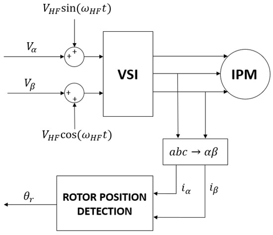
Figure 1.
Signal injection working principle.
The current response represented in Equation (6) can be deduced re-arranging Equations (2) and (1) ([9,15]).
with:
It can be noticed that the currents contain two components called, respectively, positive and negative sequence. The positive sequence contains no useful information, while the negative sequence encloses the position information through its phase. The two currents and can be represented on the Cartesian plane obtaining an ellipse. The latter contains the desired information, since it aligns with the correct rotor orientation; an example is reported in Figure 2.
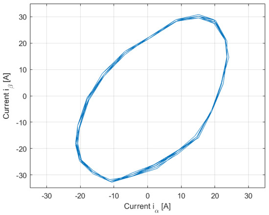
Figure 2.
Current ellipse, .
A proper demodulation algorithm must be designed for extracting the negative component while discarding the positive one. The proposed demodulation, shown in Figure 3, consists in transforming the current in a rotating frame at the injection speed, thus assuring a better spatial separation for different components, and using an highpass filter for discarding the positive sequence. Mind that the HF voltage signal is injected superimposed on the fundamental component used to drive the motor and to produce torque. This means that the currents in stationary frame will also contain a third component, rotating at , which increases in magnitude as the torque demand increases. The filter order selection is therefore crucial to discard this contribution. The effect of multiple saliencies and the high-order harmonics produced by the inverter non-linearity [13,15] also play a crucial role in the signal demodulation as they introduce useless components that have to be discarded; better results can be obtained using a properly designed bandpass filter.

Figure 3.
Demodulation algorithm.
Once isolated, the negative sequence is rotated back to stationary frame, where an heterodyning technique is applied for building an error signal as represented in Equation (8) ([9,14]).
This signal depends only on the difference between real and estimated position and can be therefore used as input for a PLL to retrieve the rotor orientation. Notice that the heterodyning technique works in closed loop and guarantees a robust behaviour. The described algorithm presents a critical issue to tackle: it can only converge in the first and fourth quarter of the Cartesian plane, which means in the interval . To overcome this problem, the paper presents a technique based on the identification of the current second harmonic, which relies on the iron magnetic saturation and in turn on the variation of the magnetic inductance, as shown in Figure 4.
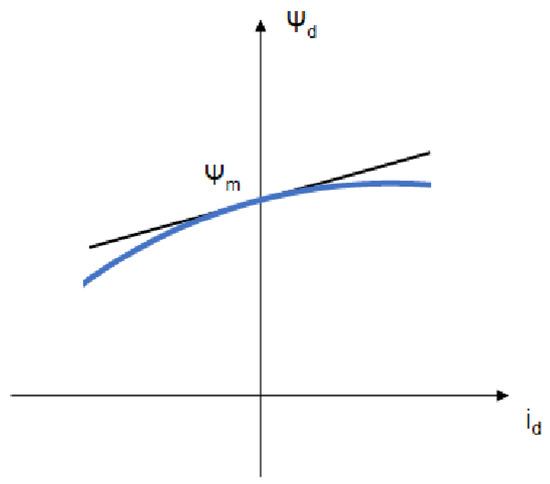
Figure 4.
d-axis magnetic saturation effect.
When a north pole of the rotor is aligned with the stator coil, the coil current increases the linked flux; as consequence, stator saturation increases too and the inductance slightly decreases. When a south pole is aligned with the coil, the opposite phenomenon happens and the inductance increases slightly. This can be represented by modelling the d-axis current in Taylor series as reported in Equation (9) [17].
where .
When a high frequency voltage is injected at standstill, the generated current at both north and south poles can be represented with Equation (10) [17].
The polarity identification can be performed by looking at the sign of the second order terms in Equation (10). Notice that the q-axis has not been taken into account for polarity detection since, assuming zero as the center of its operating point, the related linked flux is an odd function of the current and therefore has no even-order terms when expressed by the Taylor series linearized in the origin [17]. Given the above model representing the stator iron magnetic saturation, the processing of the stationary frame currents generated from a high frequency voltage injection remains the same in order to extract the negative sequence component. The only modification in the algorithm comes from a compensation of the estimation coming from the PLL, based on the polarity information. In the case of rotating injection, the current carrying this information is obtained by a heterodyning demodulation in the estimated rotor reference frame and reads as reported in Equation (11) [17]:
The sign of this current component depends on the tracked polarity and is used to eventually compensate of the angle estimation. Note that at standstill the signal extracted by the low pass filters, which reflects the sign on the second order harmonics, is likely to be very clean and can be therefore used to continuously compensate the PLL’s estimation. When the motor shaft is put into rotation and undergoes disturbances, the compensation might fail due to the small amplitude of the signal carrying information and it is therefore better to use the polarity information for correcting the estimation in feedback at standstill once for all. This operation has to be performed every time the saliency estimator is deactivated (i.e. when the motor is brought at high speeds).
3.2. V-I Observer
The presented signal injection method allows to obtain excellent results in driving an IPM motor from standstill to very high speeds, but the acoustic noise associated with the HF currents limits its application feasibility only in the region where it is strictly necessary: at standstill and start-up, up to rpm typically. Above this threshold a more classical approach can be followed, such as the design of a robust reduced order V-I estimator. The latter consists in a highly scalable application capable of retrieving the stator flux with the only knowledge of the voltages applied by the inverted and currents resulting from the machine. It operates by the reconstruction of the back-EMF, which is integrated to obtain the stator flux in stationary coordinates, as reported in Equation (13).
The estimator as presented reveals two big limitations. Firstly, it must be noticed that it is only capable of retrieving the stator angle, while an accurate control has the need of knowing the real rotor angle.
This difference is important because under load conditions the mentioned quantities differ by the so called load angle, which consists of the stator rotating magnetic flux being in advance with respect to the rotor; Figure 5 explains this phenomenon. If the load angle increases too much there might be the possibility of a loss of control and anyway the control would not result robust during loaded speed transients. To overcome this issue there is the need of retrieving the rotor angle instead of the stator one. This can be done by introducing a virtual rotor flux, aligned with the permanent magnets, as Equation (15) [9].
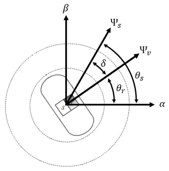
Figure 5.
Difference between stator and rotor angle.
The saliency of the machine can be therefore rewritten with some manipulation in dq coordinates as (16), where the associated magnetic fluxes are reported in Equation (17) [9].
Applying the Park anti-transform, the above equations are translated into stationary reference frame obtaining the correct angle estimation, reported respectively in Equations (18) and (19) [9].
The second limitation revealed by the V-I estimator is the weakness related to the usage of the integrator for retrieving the stator fluxes. The integrator in fact is highly affected by noises of the input, which cause drifts in the estimation. Furthermore it cannot absorb initial offsets caused by the set-up stage and bad initial conditions. This inability to compensate steady state noises can be corrected by transforming the estimator in a reduced-order observer by means of the introduction of a corrective feedback. Figure 6 depicts the implemented observer.
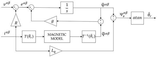
Figure 6.
Reduced order observer with rotor angle estimation.
By neglecting the outer stage which performs the rotor angle estimation and analyzing the inner loop, it can be noticed that the estimated stator flux obtained from integration is compared with a reconstructed flux coming from a magnetic model. This difference is given as feedback to the estimation of the back-EMF, by means of an amplification coefficient. The transfer function of the system if finally reported in Equation (20).
From Equation (20) it can be noticed that the integrated back-EMF is weighted by a high-pass filter which assures a fast and correct estimation during transients, while the reconstructed flux coming from the magnetic model compensates steady state offsets and drifts, being weighted by a low-pass filter. The transition of effectiveness of the two components is defined by the tuning diagonal matrix g, which represents the cutting-frequency of the digital filters. The lower is the cutting frequency, the faster the observer will success in retrieving the correct angular position but with less noise rejection. In general, a good choice of this parameter for a sensorless control is between . At last it must be remarked that the magnetic model in dq coordinates plays a crucial role in the observer robustness. In a general form is can be expressed as in Equation (21), where the dependence of the inductance from the current is highlighted.
The performance of the observer under load conditions depends on the accuracy of this magnetic model. The modelling of the inductance variation caused by magnetic saturation is crucial for a stable and robust behaviour, especially in motors which exhibits a non-perfectly sinusoidal back-EMF, that introduces a high amount of noise to be rejected as speed increases.
4. Simulation Results
Before proceeding to the experiment several preliminary simulations were carried out by means of the Simulink toolbox provided by Matlab. The model of the IPM motor with currents as state variables together with an MTPA control logic, the HF signal injection and the two estimators for high and low speeds were implemented.
At first the control was deactivated and an analysis of the currents resulting from the signal injection were conducted: Figure 7 shows that the injection of a couple of sinusoidal voltage on stationary axes produce two sinusoidal currents with a phase shift proportional to the rotor angular position, meaning that the desired information is present. At this stage the control was activated and both standstill and low speed simulations were carried out to test the performance of signal demodulation. Figure 8 shows that the saliency-based estimator succeeds in retrieving the rotor position and speed with a small error, below 15° and 1Hz respectively.
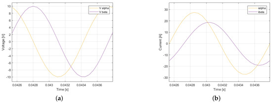
Figure 7.
Saliency-based estimator simulation. (a) Injected voltages. (b) Phase-shifted currents.
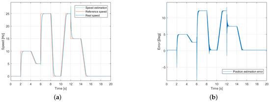
Figure 8.
Saliency-based estimator simulation. (a) Speed profile. (b) Position estimation error.
It must be noticed that the position error increases as the rotor speed increases, thus the estimator based on signal injection should be used only at speeds below 150 rpm to guarantee robust control and high efficiency. From early simulations has been found that at very low speeds very little back-EMF is present, hence the V-I observer cannot precisely estimate the rotor position. At standstill the situation is even worst, as the observer does not move at all from its initial estimation. Closing the sensorless control loop, this reflects on a very oscillatory speed estimation transient that tends to vanish as soon as some back-EMF arises (above rpm for the considered motor). Figure 9 shows this phenomenon.
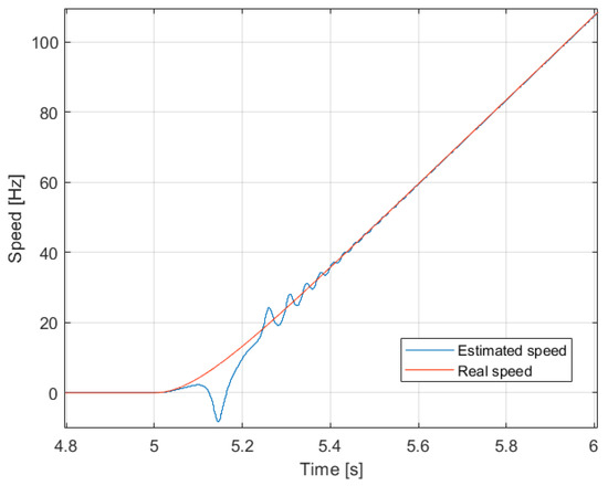
Figure 9.
V-I observer not estimating at standstill.
To overcome this problem the position estimated from the saliency-based estimator is fed to the V-I observer at standstill, then the signal injection is deactivated and the motor is driven with the latter only. From Figure 10 it can be noticed that the position estimation error tends to zero as soon as the rotor is spinning faster than the cut-off frequency “g” of the observer, showing an excellent estimation capability.
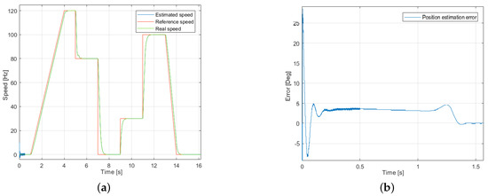
Figure 10.
V-I observer estimator simulation. (a) Speed profile. (b) Position estimation error.
Of course the driving of the motor from standstill with the only V-I observer is not suggested, as below its operational bandwidth the estimation is not robust and low torque demand can be satisfied.
5. Experimental Results
The experiments were carried out by means of the SuperSigma2 controller from DMC Gmbh, a voltage source inverter with embedded control logic which can hold either speed and torque control modes. The inverter was supplied by a power supply rated 24 V and 250 A. The tests were performed on an Ashwood IPM whose data are listed in Table 1.

Table 1.
Motor parameters.
The inner current loops were executed at 125 s, while the speed loop was tuned at 1 ms. The rotor position and speed for the sensorless control were obtained from the saliency-based estimator until 150 rpm and from the V-I observer above that speed. The changeover between the two algorithms is managed in order to have a bumpless transition both in acceleration and deceleration transient, including an hysteresis for avoiding continuous change between the algorithms when the motor speed is close to the above mentioned threshold. An analog sin-cos sensor was installed on the motor to evaluate the estimation capability of the algorithms. The hardware setup for both no-load and loaded experiments are shown in Figure 11.
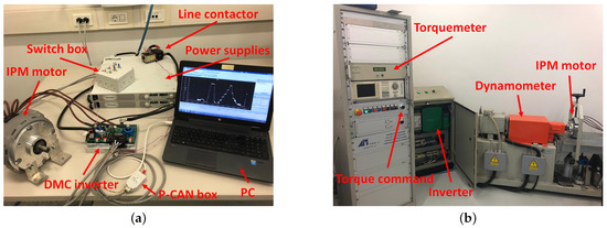
Figure 11.
Hardware setup. (a) No-load experiments. (b) Loaded experiments.
Firstly the performance of the saliency-based observer alone was tested at standstill with no load. The capability of retrieving the position information, was assessed by manually imposing position steps at the rotor; as shown in Figure 12 the estimation error oscillates around , which is a good result.
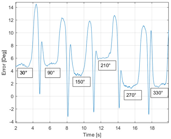
Figure 12.
Stanstill position error at imposed rotor positions.
The second test that was performed in order to assess the robustness of the saliency-based estimator under speed transient. To this means the control was activated closing both the inner and outer loop with the estimated position (used to operate Park transformations) and speed. It is remarkable that the injection frequency should be high enough to be out of the bandwidth of the current controllers, otherwise they would try to regulate the HF current to 0, thus cancelling the saliency information produced by the injection and making the estimation unfeasible. Figure 13 shows how the algorithm properly tracks the rotor position and therefore allows the control to follow different setpoints, considering both acceleration and deceleration ramps. It is worth to notice that the algorithm manages to drive the motor back to zero speed maintaining a very small error of .
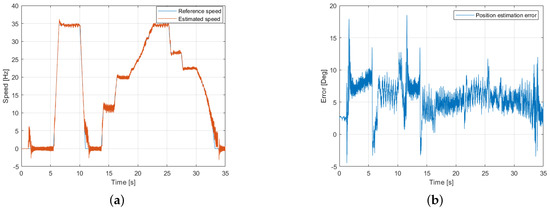
Figure 13.
Sensorless drive at low speeds using the HF injection based estimator. (a) Speed tracking. (b) Position estimation error.
Once assessed the performance at low speed, the V-I observer was introduced and a test was carried out for evaluating the transition between algorithms and the capability of the complete sensorless control to drive the motor back to 0 speed and re-start without losing the position information. Figure 14 shows that this result was achieved with the usual small position error and with a robust reaction to fast ramp setpiont: the rotor was asked to accelerate from zero to 1200 rpm in 2 s and then to decelerate to zero in the same time. It can be noticed that the speed setpoint was closely and robustly followed. Notice that the HF injection is deactivated during the acceleration transient when the V-I observer kicks in and re-activated in deceleration just before the saliency-based estimator has to restart tracking the rotor position, this for reducing the acoustic noise and increase the control efficiency. Attention must be paid on rotor position error. It is not possible, in fact, to reach zero steady state error, as can be seen in Figure 13 and Figure 14. Error can be reduced for a specific speed value by making a very precise tuning of the pass bandwidth, but this should be done for every specific application. Experimental tests show that an error estimation around on rotor position is a good trade off in terms of robustness and efficiency.
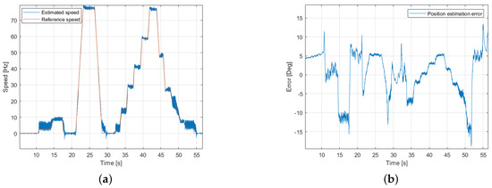
Figure 14.
Sensorless drive in a wide speed range with no load. (a) Speed tracking. (b) Position estimation error.
Finally, the torque production capability of the sensorless control was tested. These tests have been performed with a constant speed reference for the motor and applying increasing torque until its rated value. Figure 15 and Figure 16 show, respectively, a test at standstill-start-up and at 150 rpm; during those test the saliency-based estimator alone was active.
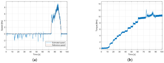
Figure 15.
Loaded behaviour at standstill and start-up. (a) Speed tracking. (b) Torque produced.
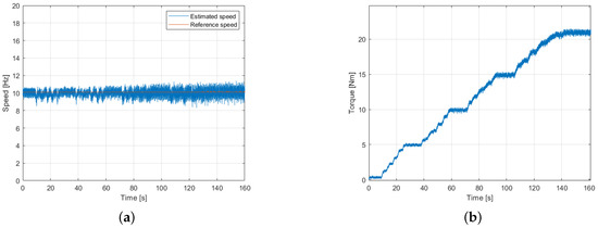
Figure 16.
Loaded behaviour at 150 rpm. (a) Speed tracking. (b) Torque produced.
At standstill lower torque is produced since the PLL gains limit the estimation bandwidth and further adjustment are necessary, but the tests showed that the estimation algorithm is robust and it allows to start the motor with at least half of the rated torque. At low speed instead rated torque production is assured. It must be remarked that in this test the HF injection is active and employing of the maximum voltage, which produces a current that is, for this motor, about the maximum value. Due to this, only of the maximum current can be used for torque production and the peak torque can not be achieved at low speed since the maximum current is not delivered for torque production only. Figure 17 also shows the importance of an accurate tuning of the band-pass filter bandwidth and order: the fundamental current used to produce torque is nearly 10 times greater in magnitude than the one which carries the position information, thus a second or third order filter is recommended.
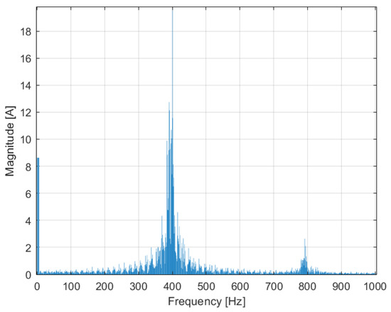
Figure 17.
Fourier analysis of the d-axis current in the synchronous injection frame.
6. Conclusions
This paper presents a new algorithm to allow the sensorless control of an IPM motor that was implemented and tested on industrial hardware. The algorithm combines two different observers for covering the widest speed range possible: at low speed an estimator tracking the motor saliency is employed together with an HF signal injection, while at medium to high speeds a modified V-I observer with internal closed-loop integrator correction was developed. The overall sensorless control succeeds in driving the motor from zero speed to the base point assuring rated torque in the whole speed range and a smooth transition between the two estimation methods. The developed algorithm has the great strength of being highly scalable and has application on a large variety of hardware and application since it relies on very few parameters, namely the PLL gains, the stator resistance and inductances and the observer bandwidth. Moreover, thanks to robustness and accuracy that this control strategy reached, the possibility to use it also in applications in which sensor is present can be considered, for example avoiding sensor damages or cabling problems.
Author Contributions
Conceptualization, F.L.M. and D.T.; Data curation, F.L.M. and S.M.; Investigation, F.L.M. and S.M.; Methodology, M.L.B., F.L.M., S.M. and M.V.; Software, S.M.; Supervision, F.L.M.; Validation, D.T.; Writing—review & editing, M.L.B., F.L.M., S.M., D.T. and M.V. All authors have read and agreed to the published version of the manuscript.
Funding
This research received no external funding.
Conflicts of Interest
The authors declare no conflict of interest.
References
- Tursini, M.; Petrella, R.; Parasiliti, F. Sensorless control of an IPM synchronous motor for city-scooter applications. In Proceedings of the 38th IAS Annual Meeting on Conference Record of the Industry Applications Conference, Salt Lake City, UT, USA, 12–16 October 2003; Volume 3, pp. 1472–1479. [Google Scholar]
- Vagati, A.; Pellegrino, G.; Guglielmi, P. Comparison between SPM and IPM motor drives for EV application. In Proceedings of the XIX International Conference on Electrical Machines-ICEM, Rome, Italy, 6–8 September 2010; Volume 3, pp. 1–6. [Google Scholar]
- Pellegrino, G.; Vagati, A.; Guglielmi, P.; Boazzo, B. Performance Comparison Between Surface-Mounted and Interior PM Motor Drives for Electric Vehicle Application. IEEE Trans. Ind. Electr. 2012, 59, 803–811. [Google Scholar] [CrossRef]
- Zhu, Z.Q.; Chan, C.C. Electrical machine topologies and technologies for electric, hybrid, and fuel cell vehicles. In Proceedings of the IEEE Vehicle Power and Propulsion Conference, Harbin, China, 3–5 September 2008; pp. 1–6. [Google Scholar]
- Awan, H.A.A.; Tuovinen, T.; Saarakkala, S.E.; Hinkkanen, M. Discrete-Time Observer Design for Sensorless Synchronous Motor Drives. IEEE Trans. Ind. Appl. 2016, 52, 3968–3979. [Google Scholar] [CrossRef]
- Foo, G.; Rahman, M.F. Sensorless Sliding-Mode MTPA Control of an IPM Synchronous Motor Drive Using a Sliding-Mode Observer and HF Signal Injection. IEEE Trans. Ind. Electron. 2010, 57, 1270–1278. [Google Scholar] [CrossRef]
- Kim, J.H.; Lee, S.S.; Kim, R.Y.; Hyun, D.S. A sensorless control using Extended Kalman Filter for an IPM synchronous motor based on an extended rotor flux. In Proceedings of the 38th Annual Conference on IEEE Industrial Electronics Society, Montreal, QC, Canada, 25–28 October 2012; pp. 1631–1636. [Google Scholar]
- Foo, G.; Sayeef, S.; Rahman, M.F. An Extended Kalman filter for sensorless direct torque controlled IPM synchronous motor drive. In Proceedings of the IEEE International Conference on Power and Energy, Sydney, Australia, 14–17 December 2008; pp. 271–276. [Google Scholar]
- Xu, Z.; Rahman, M.F.; Wang, G.; Xu, D. Performance Evaluation of an Integrated Starter-Alternator with an IPM Synchronous Machine under Sensor-less Operation. J. Power Electron. 2012, 12, 49–57. [Google Scholar] [CrossRef][Green Version]
- Parasiliti, F.; Petrella, R.; Tursini, M. Speed sensorless control of an interior PM synchronous motor. In Proceedings of the Conference Record of the 2002 IEEE-Industry Applications Society Annual Meeting, Pittsburgh, PA, USA, 13–18 October 2002; Volume 1, pp. 657–664. [Google Scholar]
- Zhang, G.; Wang, G.; Xu, D. Saliency-based position sensorless control methods for PMSM drives—A review. Chin. J. Electr. Eng. 2017, 3, 14–23. [Google Scholar]
- Xie, G.; Lu, K.; Xu, D.; Dwivedi, S.K.; Rosholm, J.R. Improved INFORM method by minimizing the inverter nonlinear voltage error effects. In Proceedings of the IEEE Workshop on Electrical Machines Design, Control and Diagnosis (WEMDCD), Torino, Italy, 26–27 March 2015; pp. 188–194. [Google Scholar]
- Raca, D.; Garcia, P.; Reigosa, D.; Briz, F.; Lorenz, R.D. A comparative analysis of pulsating vs. rotating vector carrier signal injection-based sensorless control. In Proceedings of the Twenty-Third Annual IEEE Applied Power Electronics Conference and Exposition, Austin, TX, USA, 24–28 February 2008; pp. 879–885. [Google Scholar]
- Kim, H.; Lorenz, R.D. Carrier signal injection based sensorless control methods for IPM synchronous machine drives. In Proceedings of the 39th IAS Annual Meeting, Conference Record of the 2004 IEEE Industry Applications Conference, Seattle, WA, USA, 3–7 October 2004; Volume 2, pp. 977–984. [Google Scholar]
- Caruana, C.; Asher, G.M.; Sumner, M. Performance of HF signal injection techniques for zero-low-frequency vector control of induction Machines under sensorless conditions. IEEE Trans. Ind. Electron. 2006, 53, 225–238. [Google Scholar] [CrossRef]
- Ribeiro, A.S.; Degner, M.W.; Briz, F.; Lorenz, R. Comparison of carrier signal voltage and current injection for the estimation of flux angle or rotor position. In Proceedings of the Thirty-Third IAS Annual Meeting, Conference Record of 1998 IEEE Industry Applications Conference, St. Louis, MO, USA, 12–15 October 1998; Volume 1, pp. 452–459. [Google Scholar]
- Jeong, Y.; Lorenz, R.D.; Jahns, T.M.; Sul, S.-K. Initial rotor position estimation of an interior permanent-magnet synchronous machine using carrier-frequency injection methods. In Proceedings of the IEEE International Electric Machines and Drives Conference (IEMDC 2003), Madison, WI, USA, 1–4 June 2003; Volume 2, pp. 1218–1223. [Google Scholar]
© 2020 by the authors. Licensee MDPI, Basel, Switzerland. This article is an open access article distributed under the terms and conditions of the Creative Commons Attribution (CC BY) license (http://creativecommons.org/licenses/by/4.0/).