Aerodynamic Simulations for Floating Darrieus-Type Wind Turbines with Three-Stage Rotors


Abstract
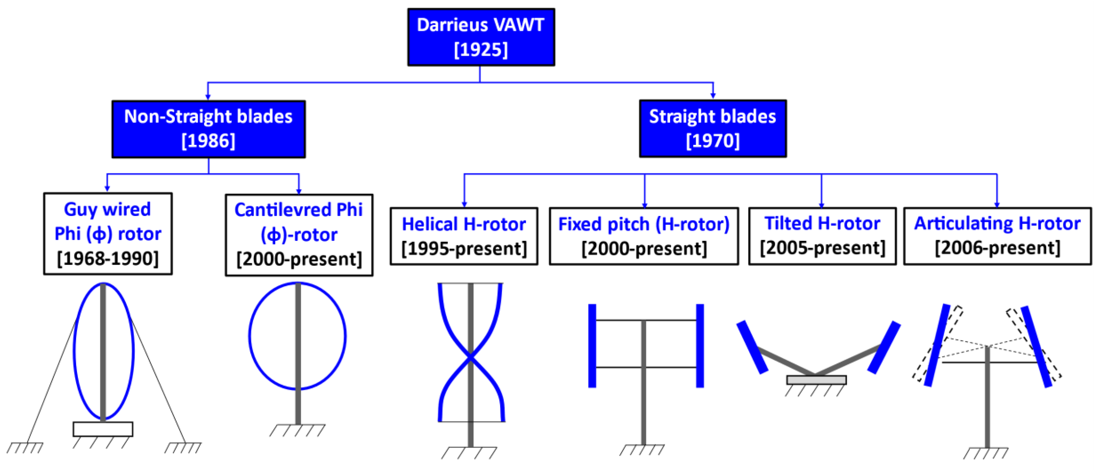
1. Introduction
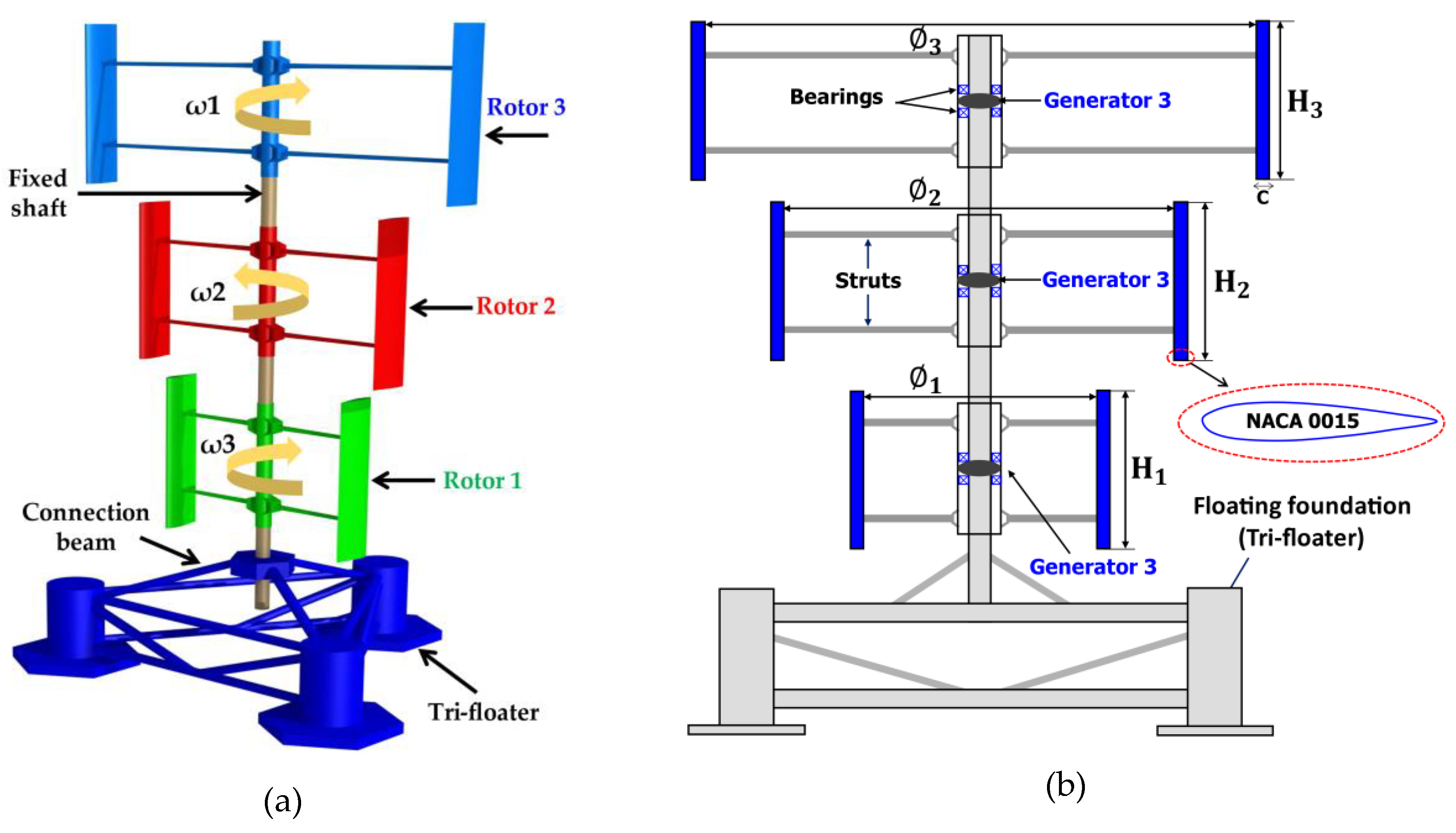
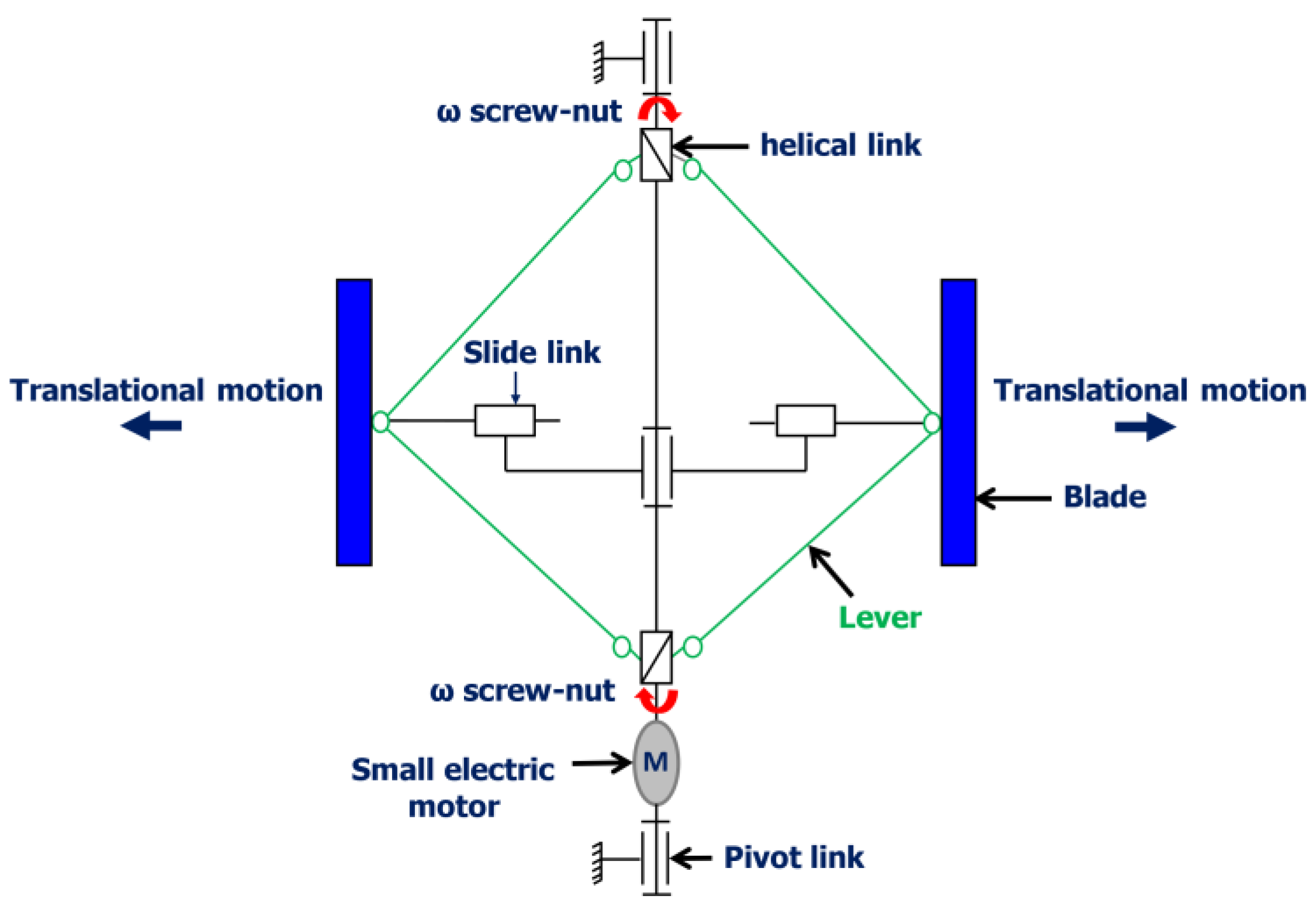
2. Floating Darrieus-Type Wind Turbine with Three-Stage Rotors
3. General Mathematical Expressions for Aerodynamic Analysis of SB-VAWT
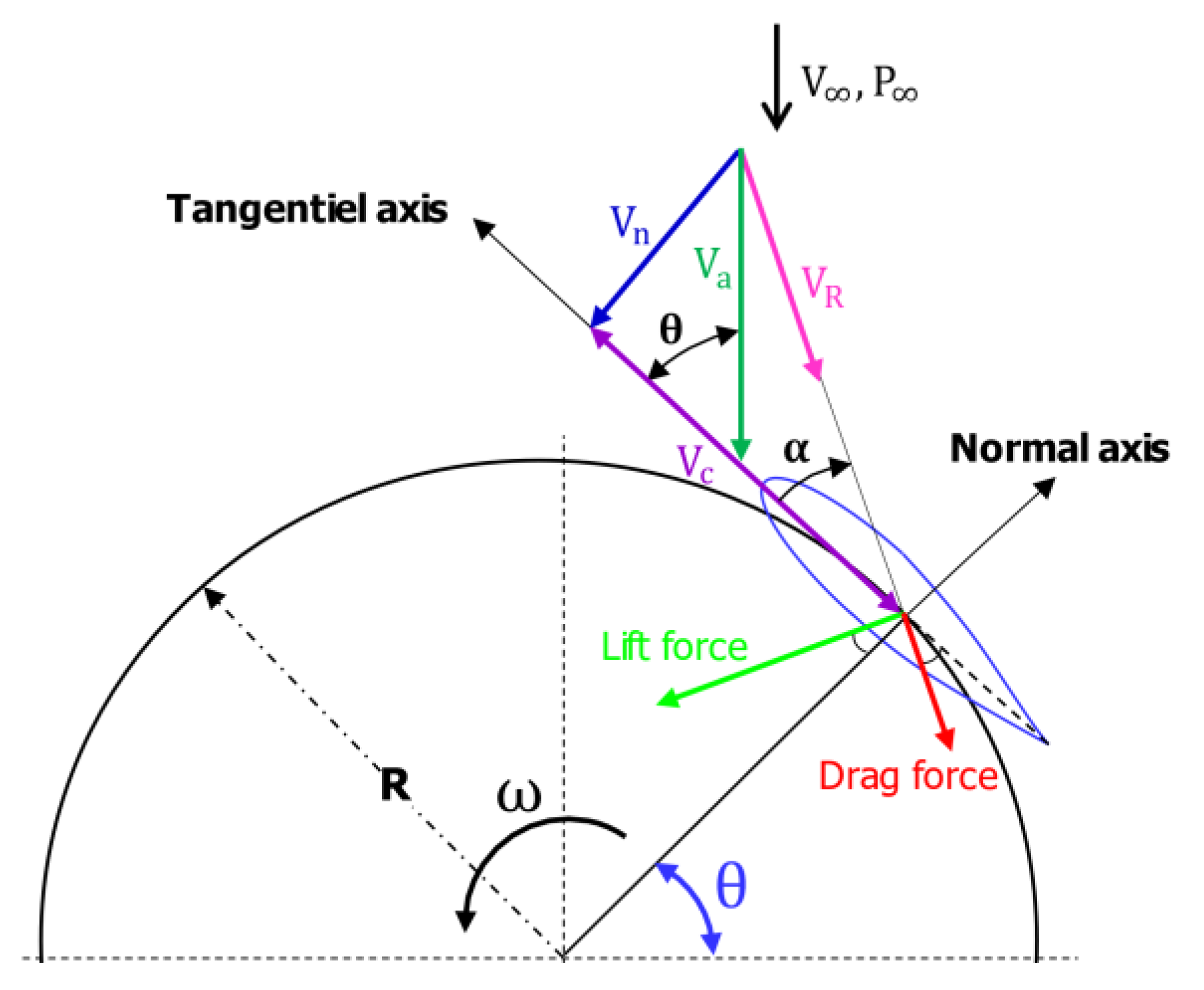
3.1. Local Relative Velocity Variation
3.2. Variation of Local Angle of Attack
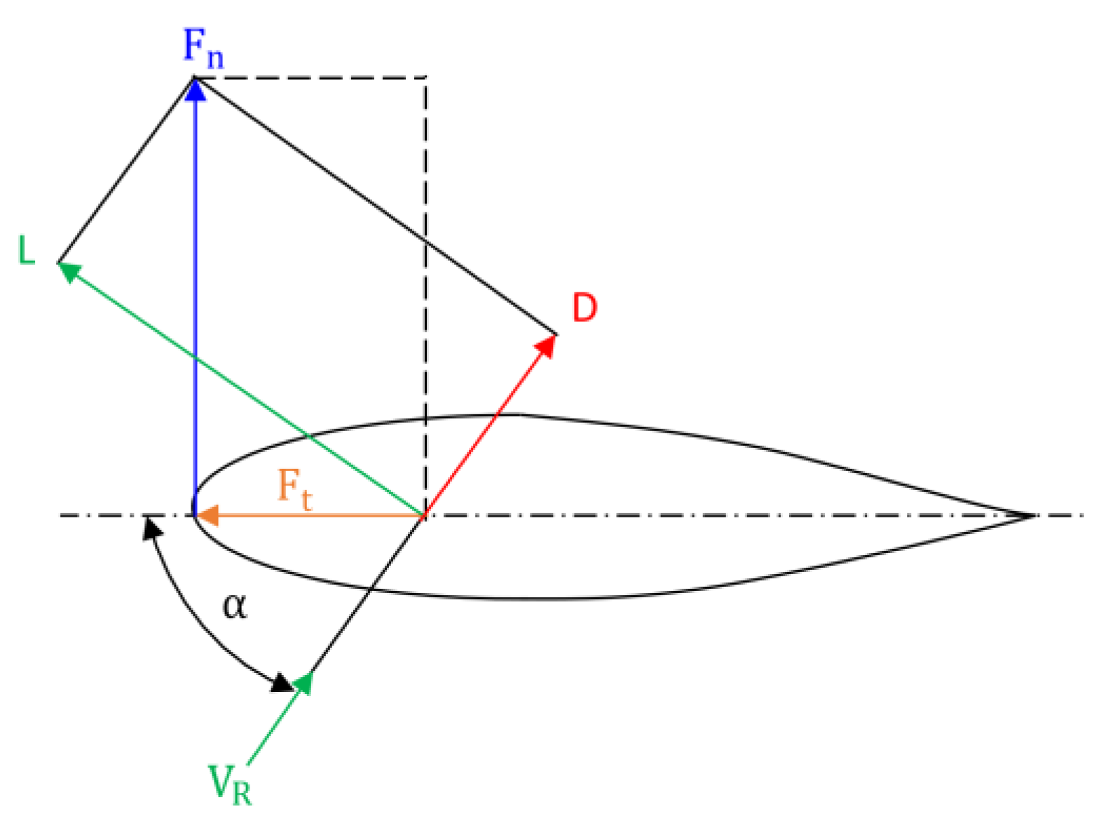
3.3. Normal and Tangential Force Variation
3.4. Total Torque and Power Output
3.5. Rotor Solidity σ
3.6. Rotor Aspect Ratio AR
3.7. Power Coefficient Cp
3.8. Reynolds Number Re
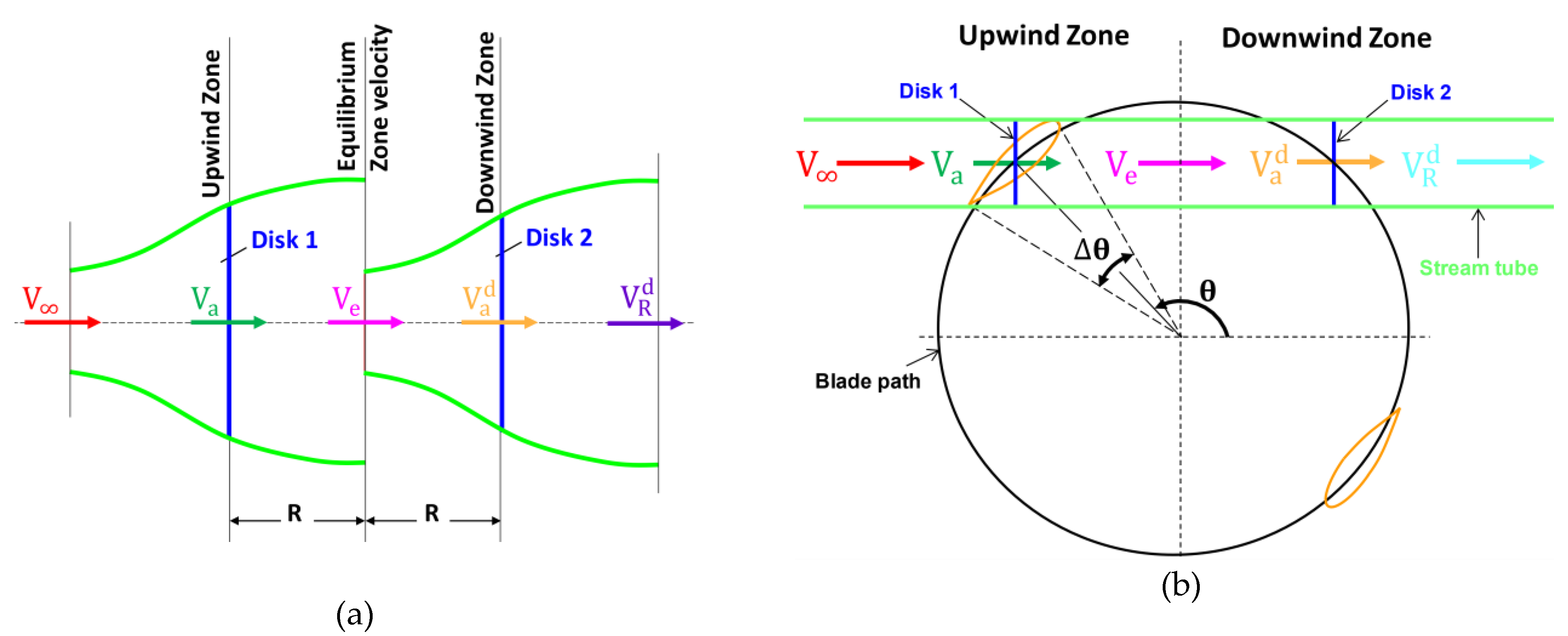
4. Double Multiple Stream Tube Model
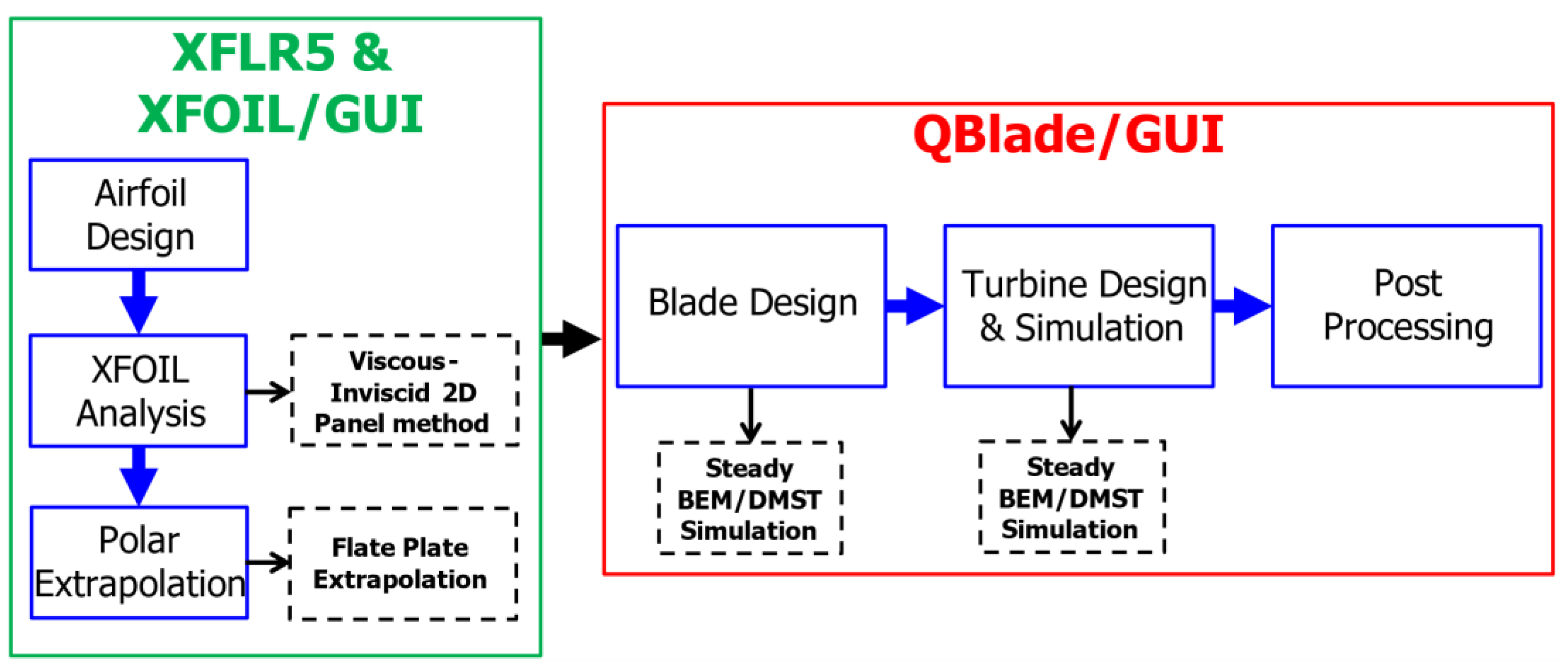
4.1. QBlade Simulation Tool
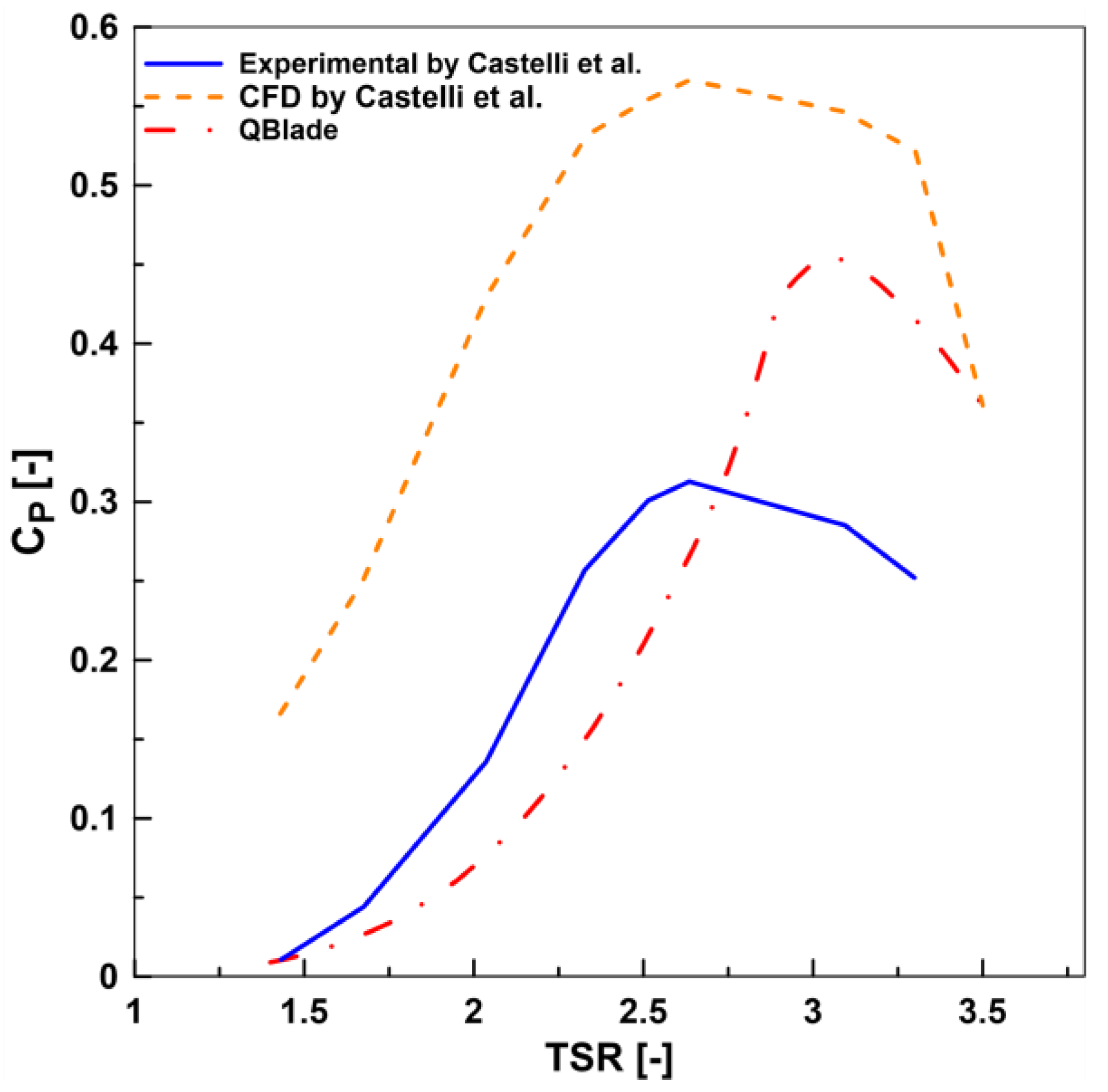
4.2. QBlade Validation
4.3. Input Parameters Used for the Aerodynamic Simulation
5. Results and Discussion
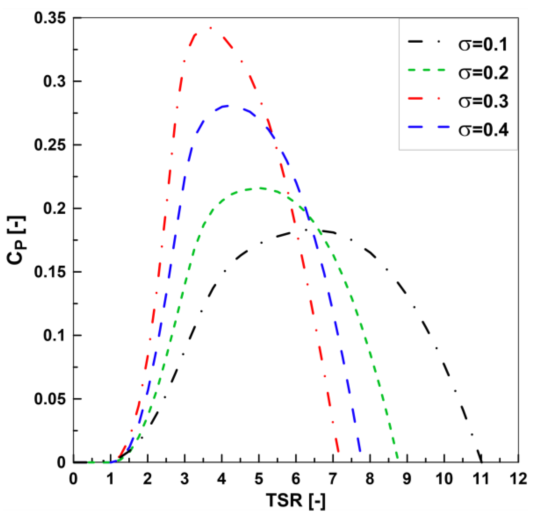
5.1. Rotor Solidity
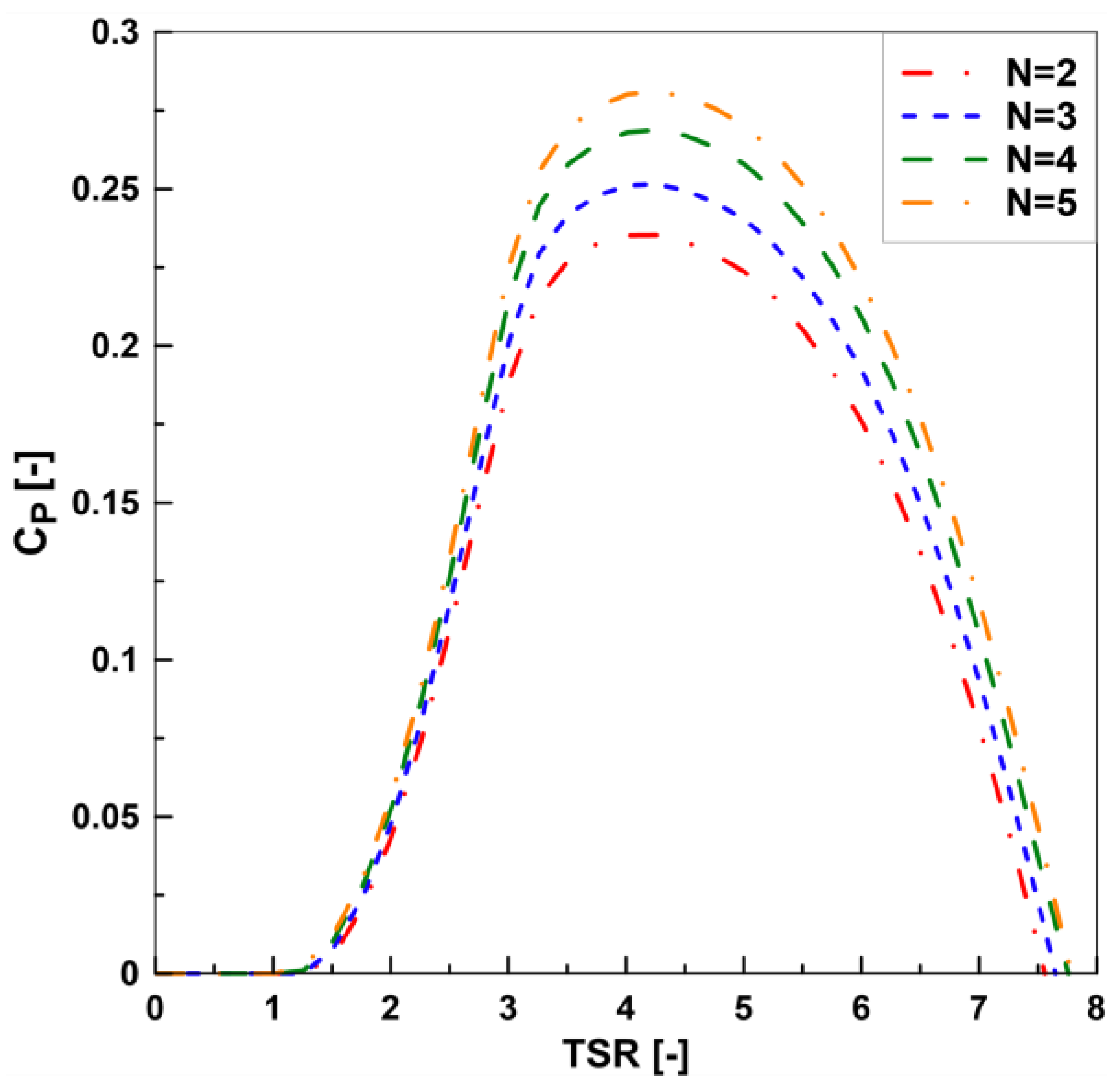
5.2. Number of Blades
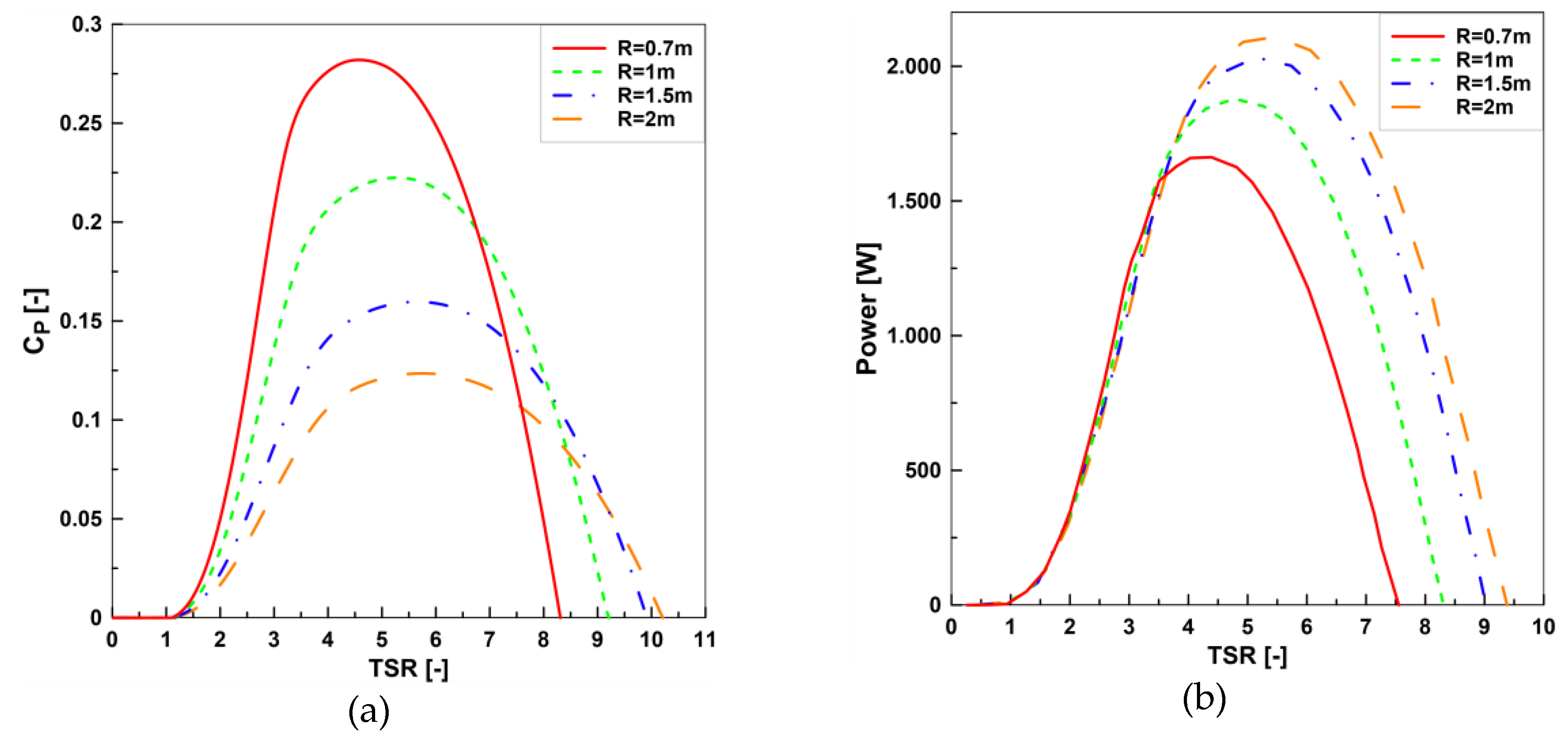
5.3. Rotor Radius
5.4. Rotor Aspect Ratio
5.5. Wind Speed with Rotor Height
6. Conclusions
Author Contributions
Funding
Acknowledgments
Conflicts of Interest
Nomenclature
| A | turbine swept area, m2 (A = 2hR) |
| , | upwind and downwind induction factors |
| B | number of blades |
| c | blade chord length, m |
| drag coefficient | |
| lift coefficient | |
| normal coefficient | |
| moment coefficient | |
| tangential coefficient | |
| power coefficient | |
| D | blade drag force, N |
| upwind and downwind functions | |
| normal and tangential force, N | |
| average tangential force, N | |
| h | height of the blade/turbine, m |
| L | blade lift force, N |
| total power output | |
| total torque output | |
| R | radius of the wind turbine, m |
| local Reynold number | |
| upstream induced velocity, m/s | |
| upstream and downstream induced velocity, m/s | |
| chordal velocity component, m/s | |
| normal velocity component, m/s | |
| relative velocity upstream, m/s | |
| relative velocity downstream, m/s | |
| free-stream velocity, m/s | |
| blade angle of attack | |
| upstream and downstream angle of attack | |
| azimuth angle increment, correspond to one stream tube | |
| azimuth angle | |
| TSR | tip speed ratio |
| density of the air (kg/m3) | |
| dynamic viscosity of the air (kg/m.s) | |
| solidity | |
| angular velocity of rotor, rad/s |
Acronyms
| DMST | double multiple stream tube |
| F-VAWTs | floating vertical axis wind turbines |
| F-HAWTs | floating horizontal axis wind turbines |
| HAWT | horizontal axis wind turbine |
| MST | multiple stream tube |
| SKWID | Savonius keel wind turbine Darrieus |
| SB-VAWT | straight-bladed vertical axis wind turbine |
| PMSMs | permanent-magnet synchronous motors |
References
- IRENA. Future of Wind: Deployment, Investment, Technology, Grid Integration and Socio-Economic Aspects, (A Global Energy Transformation Paper); International Renewable Energy Agency: Abu Dhabi, UAE, 2019. [Google Scholar]
- Onea, F.; Rusu, E. Efficiency assessments for some state of the art wind turbines in the coastal environments of the Black and the Caspian seas. Energy Explor. Exploit. 2016, 34, 217–234. [Google Scholar] [CrossRef]
- Rusu, E.; Onea, F. Joint Evaluation of the Wave and Offshore Wind Energy Resources in the Developing Countries. Energies 2017, 10, 1866. [Google Scholar] [CrossRef]
- Rusu, E.; Onea, F. A parallel evaluation of the wind and wave energy resources along the Latin American and European coastal environments. Renew. Energy 2019, 143, 1594–1607. [Google Scholar] [CrossRef]
- Borg, M.; Shires, A.; Collu, M. Offshore floating vertical axis wind turbines, dynamics modelling state of the art. Part I: Aerodynamics. Renew. Sustain. Energy Rev. 2014, 39, 1214–1225. [Google Scholar] [CrossRef]
- Shen, X.; Hu, P.; Chen, J.; Zhu, X.; Du, Z. The unsteady aerodynamics of floating wind turbine under platform pitch motion. Proc. Inst. Mech. Eng. Part A J. Power Energy 2018, 232, 1019–1036. [Google Scholar] [CrossRef]
- Burton, T.; Sharpe, D.; Jenkins, N.; Bossanyi, E. Wind Energy Handbook; John Wiley and Sons Ltd.: Chichester, UK, 2001; p. 45. [Google Scholar]
- Amiri, M.; Teymourtash, A.; Kahrom, M. Experimental and numerical investigations on the aerodynamic performance of a pivoted Savonius wind turbine. Proc. Inst. Mech. Eng. Part A J. Power Energy 2017, 231, 87–101. [Google Scholar] [CrossRef]
- Roy, S.; Saha, U.K. Review of experimental investigations into the design, performance and optimization of the Savonius rotor. Proc. Inst. Mech. Eng. Part A J. Power Energy 2013, 227, 528–542. [Google Scholar] [CrossRef]
- Tjiu, W.; Marnoto, T.; Mat, S.; Ruslan, M.H.; Sopian, K. Darrieus vertical axis wind turbine for power generation I: Assessment of Darrieus VAWT configurations. Renew. Energy 2015, 75, 50–67. [Google Scholar] [CrossRef]
- Tjiu, W.; Marnoto, T.; Mat, S.; Ruslan, M.H.; Sopian, K. Darrieus vertical axis wind turbine for power generation II: Challenges in HAWT and the opportunity of multi-megawatt Darrieus VAWT development. Renew. Energy 2015, 75, 560–571. [Google Scholar] [CrossRef]
- Scheurich, F.; Fletcher, T.M.; Brown, R.E. Effect of blade geometry on the aerodynamic loads produced by vertical-axis wind turbines. Proc. Inst. Mech. Eng. Part A J. Power Energy 2011, 225, 327–341. [Google Scholar] [CrossRef]
- Musial, W.; Butterfield, S.; Ram, B. Energy from Offshore Wind. In Proceedings of the Offshore Technology Conference 2006, Houston, TX, USA, 1–4 May 2006. [Google Scholar]
- Willis, D.; Niezrecki, C.; Kuchma, D.; Hines, E.; Arwade, S.; Barthelmie, R.; DiPaola, M.; Drane, P.; Hansen, C.; Inalpolat, M.; et al. Wind energy research: State-of-the-art and future research directions. Renew. Energy 2018, 125, 133–154. [Google Scholar] [CrossRef]
- Hou, P.; Zhu, J.; Ma, K.; Yang, G.; Hu, W.; Chen, Z. A review of offshore wind farm layout optimization and electrical system design methods. J. Mod. Power Syst. Clean Energy 2019, 7, 975–986. [Google Scholar] [CrossRef]
- Akimoto, H.; Tanaka, K.; Uzawa, K. Floating axis wind turbines for offshore power generation—A conceptual study. Environ. Res. Lett. 2011, 6, 044017. [Google Scholar] [CrossRef]
- Nakamura, T.; Mizumukai, K.; Akimoto, H.; Hara, Y.; Kawamura, T. Floating Axis Wind and Water Turbine for High Utilization of Sea Surface Area: Design of Sub-Megawatt Prototype Turbine. In Proceedings of the ASME 2013 32nd International Conference on Ocean, Offshore and Arctic Engineering, Nantes, France, 9–14 June 2013. [Google Scholar]
- Dominy, R.; Lunt, P.; Bickerdyke, A.; Dominy, J. Self-starting capability of a Darrieus turbine. Proc. Inst. Mech. Eng. Part A J. Power Energy 2007, 221, 111–120. [Google Scholar] [CrossRef]
- Hill, N.; Dominy, R.; Ingram, G.; Dominy, J. Darrieus turbines: The physics of self-starting. Proc. Inst. Mech. Eng. Part A J. Power Energy 2009, 223, 21–29. [Google Scholar] [CrossRef]
- Cahay, M.; Luquiau, E.; Smadja, C.; Silvert, F. Use of a Vertical Wind Turbine in an Offshore Floating Wind Farm. In Proceedings of the Offshore Technology Conference, Houston, TX, USA, 2–5 May 2011. [Google Scholar]
- Chinman, S.A. Analysis, Hybrid Testing and Orientation Control of a Floating Platform with Counter-Rotating Vertical-Axis Wind Turbines. Ph.D. Thesis, University of California, Berkeley, CA, USA, 2015. [Google Scholar]
- Paulsen, U.S.; Pedersen, T.F.; Madsen, H.A.; Enevoldsen, K.; Nielsen, P.H.; Hattel, J.H.; Zanne, L.; Battisti, L.; Brighenti, A.; Lacaze, M.; et al. Deepwind-an innovative wind turbine concept for offshore. In Proceedings of the EWEA Annual Event. European Wind Energy Association (EWEA), Brussels, Belgium, 14–17 March 2011. [Google Scholar]
- Hunter, P.C. Multi-megawatt vertical axis wind turbine. In Proceedings of the Hamburg Offshore Wind Conference, VertAx Wind Limited, Hamburg, Germany, 17 April 2009. [Google Scholar]
- Shires, A. Development and Evaluation of an Aerodynamic Model for a Novel Vertical Axis Wind Turbine Concept. Energies 2013, 6, 2501–2520. [Google Scholar] [CrossRef]
- Islam, M.; Ting, D.; Fartaj, A. Aerodynamic models for Darrieus-type straight-bladed vertical axis wind turbines. Renew. Sustain. Energy Rev. 2006, 12, 1087–1109. [Google Scholar] [CrossRef]
- Blonk, D.L. Conceptual Design and Evaluation of Economic Feasibility of Floating Vertical Axis Wind Turbines. Master’s Thesis, Delft University of Technology, Delft, The Netherlands, 2010. [Google Scholar]
- Manwell, J.F.; McGowan, J.G.; Rogers, A.L. Wind Energy Explained: Theory, Design and Application, 2nd ed.; John Wiley and Sons Ltd.: Hoboken, NJ, USA, 2010; pp. 158–164. [Google Scholar]
- Ahmadi-Baloutaki, M.; Carriveau, R.; Ting, D.S.-K. Straight-bladed vertical axis wind turbine rotor design guide based on aerodynamic performance and loading analysis. Proc. Inst. Mech. Eng. Part A J. Power Energy 2014, 228, 742–759. [Google Scholar] [CrossRef]
- Mohammed, A.A.; Ouakad, H.M.; Sahin, A.Z.; Bahaidarah, H.M.S. Vertical Axis Wind Turbine Aerodynamics: Summary and Review of Momentum Models. J. Energy Resour. ASME 2019, 141, 050801–0508010. [Google Scholar] [CrossRef]
- Beaudet, L. Étude Expérimentale et Numérique du Décrochage Dynamique sur une Éolienne à axe Vertical de Forte Solidité. Ph.D. Thesis, Poitiers University, Poitiers, France, 2006. [Google Scholar]
- Strickland, J.H. The Darrieus turbine: A performance prediction model using multiple streamtube. In Report of Sandia National Laboratories; Sandia National Laboratories: Albuquerque, NM, USA, 1975. [Google Scholar]
- Paraschivoiu, I. Wind Turbine Design: With Emphasis on Darrieus Concept; Polytechnic International Press: Montréal, QC, Canada, 2002; pp. 365–366. [Google Scholar]
- Nachtan, M.; Tarfaoui, M.; El Moumen, A.; Saifaoui, D.; Benyahia, H. Design and Hydrodynamic Performance of a Horizontal Axis Hydrokinetic Turbine. IJAME 2019, 16, 6453–6469. [Google Scholar]
- Marten, D.; Wendler, J. QBlade Guidelines v0.6; TU Berlin: Berlin, Germany, 2013. [Google Scholar]
- Castelli, M.R.; Englaro, A.; Benini, E. The Darrieus wind turbine: Proposal for a new performance prediction model based on CFD. Energy 2011, 36, 4919–4934. [Google Scholar] [CrossRef]
- Rezaeiha, A.; Montazeri, B.; Blocken, B. Characterization of aerodynamic performance of vertical axis wind turbines: Impact of operational parameters. Energy Convers. Manag. 2018, 69, 45–77. [Google Scholar] [CrossRef]
- Montgomerie, B. Methods for Root Effects, Tip Effects and Extending the Angle of Attack Range to 180°, with Application to Aerodynamics for Blades on Wind Turbines and Propellers; Swedish Defence Research Agency: Stockholm, Sweden, 2004. [Google Scholar]
- Mahmuddin, F.; Klara, S.; Sitepu, H.; Hariyanto, S. Airfoil Lift and Drag Extrapolation with Viterna and Montgomerie Methods. Energy Procedia 2017, 105, 811–816. [Google Scholar] [CrossRef]
- Viterna, L.A.; Janetzke, D.C. Theoretical and Experimental Power from Large Horizontal-Axis Wind Turbines; Technical Report, DOE/NASA/20320-41, NASA-TM-82944, ON: DE83001099; DOE’s Office of Scientific and Technical Information (OSTI): Cleveland, OH, USA, 1982. [Google Scholar]
- Kumar, P.M.; Rashmitha, S.R.; Srikanth, N.; Lim, T.C. Wind Tunnel Validation of Double Multiple Streamtube Model for Vertical Axis Wind Turbine. Smart Grid Renew. Energy 2017, 8, 412–424. [Google Scholar] [CrossRef][Green Version]
- Islam, P.M.; Ting, D.S.-K.; Fartaj, A. Design of a Special-purpose Airfoil for Smaller-Capacity Straight-Bladed VAWT. Wind. Eng. 2007, 31, 401–424. [Google Scholar] [CrossRef]
- Brusca, S.; Lanzafame, R.; Messina, M. Design of a vertical-axis wind turbine: How the aspect ratio affects the turbine’s performance. Int. J. Energy Environ. Eng. 2014, 5, 333–340. [Google Scholar] [CrossRef]
- Meana-Fernández, A.; Oro, J.M.F.; Díaz, K.A.; Vega, M.G.; Velarde-Suárez, S. Aerodynamic Design of a Small-Scale Model of a Vertical Axis Wind Turbine. Proceedings 2018, 2, 1465. [Google Scholar] [CrossRef]
- Castelli, M.R.; Betta, S.D.; Benini, E. Effect of Blade Number on a Straight-Bladed Vertical-Axis Darreius Wind Turbine. Int. J. Aerosp. Mech. Eng. 2012, 6, 68–74. [Google Scholar]
- Sutherland, H.J.; Berg, D.E.; Ashwill, T.D. A retrospective of VAWT technology. In Report of Sandia National Laboratories; Sandia National Laboratorie: Albuquerque, NM, USA, 2012. [Google Scholar]
- Sahim, K.; Santoso, D.; Puspitasari, D. Investigations on the Effect of Radius Rotor in Combined Darrieus-Savonius Wind Turbine. Int. J. Rotating Mach. 2018, 2018, 3568542. [Google Scholar] [CrossRef]


| BEM Model | Cascade Model | Vortex Model | Panel Model | |
|---|---|---|---|---|
| Complexity | Low-Medium | Low-Medium | Medium-High | High |
| Ease of implementation | Easy-Medium | Easy-Medium | Medium | Hard |
| Computational effort | Low | Low | Medium-High | Medium-High |
| Restricted to known airfoils | Yes | Yes | Yes | No |
| Incorporate unsteady conditions | Limited | Limited | Yes | Yes |
| Rotor wake/multiple rotor interactions | No/No | No/No | Yes/Limited | Yes/Yes |
| TSR | |||||
|---|---|---|---|---|---|
| 1.69224 | 0.0477033 | 0.0276889 | 0.26065 | 53.09408666 | 138.1186451 |
| 2.00088 | 0.127525 | 0.067902 | 0.412182 | 61.0181807 | 105.4857543 |
| 2.30071 | 0.249668 | 0.141027 | 0.523215 | 55.61422593 | 70.78613451 |
| 2.60494 | 0.310683 | 0.248951 | 0.563603 | 22.06156166 | 57.85749743 |
| 2.90035 | 0.297405 | 0.427411 | 0.554072 | 35.87282841 | 60.28747694 |
| 3.05908 | 0.285123 | 0.453624 | 0.546477 | 45.61805327 | 62.85569986 |
| 3.20899 | 0.267197 | 0.435643 | 0.530408 | 47.93295771 | 66.00033851 |
| Rotor | R [m] | c [m] | h [m] | B | σ | |
|---|---|---|---|---|---|---|
| 1. Aerodynamic airfoils | ||||||
| 1 | 0.7 | 0.09 | 0.45 | 3 | 10 | 0.38 |
| 2. Rotor solidity | ||||||
| 1 | 2 | 0.0667 | 0.45 | 3 | 10 | 0.1 |
| 2 | 1.5 | 0.1 | 0.2 | |||
| 3 | 1 | 0.1 | 0.3 | |||
| 4 | 0.7 | 0.0933 | 0.4 | |||
| 3. Number of blades | ||||||
| 1 | 0.7 | 0.105 | 0.45 | 2 | 10 | 0.3 |
| 2 | 1 | 0.1 | 3 | |||
| 3 | 1.5 | 0.1125 | 4 | |||
| 4 | 2 | 0.12 | 5 | |||
| 4. Rotor radius | ||||||
| 1 | 0.7 | 0.105 | 0.45 | 2 | 10 | 0.3 |
| 2 | 1 | 0.15 | ||||
| 3 | 1.5 | 0.225 | ||||
| 4 | 2 | 0.3 | ||||
| 5. Rotor aspect ratio | ||||||
| 1 | 0.7 | 0.105 | 0.28 | 2 | 10 | 0.3 |
| 2 | 1 | 0.15 | 0.8 | |||
| 3 | 1 | 0.15 | 1 | |||
| 4 | 1.5 | 0.225 | 1.8 | |||
| 5 | 2 | 0.3 | 3.2 | |||
| 6. Wind speed/Rotor height | ||||||
| 1 | 2.5 | 0.375 | 1 | 2 | 10 | 0.3 |
| 2 | 3.75 | 0.5625 | 1.5 | 12 | ||
| 3 | 5 | 0.75 | 2 | 14 | ||
| 106 | 1.225 | 1.647 · 10−5 |
© 2020 by the authors. Licensee MDPI, Basel, Switzerland. This article is an open access article distributed under the terms and conditions of the Creative Commons Attribution (CC BY) license (http://creativecommons.org/licenses/by/4.0/).
Share and Cite
Dabachi, M.A.; Rahmouni, A.; Rusu, E.; Bouksour, O. Aerodynamic Simulations for Floating Darrieus-Type Wind Turbines with Three-Stage Rotors. Inventions 2020, 5, 18. https://doi.org/10.3390/inventions5020018
Dabachi MA, Rahmouni A, Rusu E, Bouksour O. Aerodynamic Simulations for Floating Darrieus-Type Wind Turbines with Three-Stage Rotors. Inventions. 2020; 5(2):18. https://doi.org/10.3390/inventions5020018
Chicago/Turabian StyleDabachi, Mohamed Amine, Abdellatif Rahmouni, Eugen Rusu, and Otmane Bouksour. 2020. "Aerodynamic Simulations for Floating Darrieus-Type Wind Turbines with Three-Stage Rotors" Inventions 5, no. 2: 18. https://doi.org/10.3390/inventions5020018
APA StyleDabachi, M. A., Rahmouni, A., Rusu, E., & Bouksour, O. (2020). Aerodynamic Simulations for Floating Darrieus-Type Wind Turbines with Three-Stage Rotors. Inventions, 5(2), 18. https://doi.org/10.3390/inventions5020018