Abstract
Harmonics are regarded as one of the main challenges in a microgrid. This issue may even get worse when different distributed generators (DGs) work together to solve the load sharing problems due to mismatched feeder impedances and diversified DG ratings. Even though load sharing can be achieved, the microgrid suffers from voltage unbalance and total harmonic distortion (THD) issues at the output of DG terminals as well as at the point of common coupling (PCC). Thus, in this paper, the power quality improving method is discussed, with a target of load sharing under the hierarchical control of different DG units and an active power filter (APF) in microgrids. To achieve this objective, we propose integrating a direct harmonic voltage controlled APF with DGs to improve their harmonic compensation performance. This proposed control scheme has many advantages over conventional control using a shunt resistive active power filter (R-APF) with voltage controlled DGs. First, based on the existing THD level of the PCC voltage, the proposed scheme provides improved voltage compensation and reduction in THD in the islanded microgrid. Secondly, equal load sharing can be achieved simultaneously. Thus, the proposed scheme provides better performance and a seamless interface as the proposed study mainly contains both the voltage controlled DGs and the local based voltage detection APF.
1. Introduction
Harmonic distortion is one of the main power quality issues associated with the electrical power grid [1]. With the high proliferation of nonlinear loads in the electrical distribution system, harmonics-related power quality issues have increased a lot. As a result, power system voltage and current waveforms deteriorate and do not remain sinusoidal. The harmonics present in the load current trip the circuit breaker and cause the neutral current to be large. In some cases, it overheats the transformers and blows the fuses [2]. This eventually degrades the power quality of the power grid, which causes it to become a major concern in modern power systems.
Many renewable energy technologies such as photovoltaic panels, variable speed type wind turbines, micro-turbines, gas engines, fuel cells, flywheels, and super-capacitors are increasingly being connected to electric power distribution systems. To interconnect these renewable electrical technologies to the utility power grid, power converters are usually employed as they are taken into consideration as an efficient interface for distributed renewable generation units [3]. The main goal of interfacing power converters is to regulate the active and reactive power introduced by the DGs. Higher penetration and uncoordinated control of these power electronic interfaced converters can lead to harmonic distortions in the power distribution system, which may exceed IEEE standards. However, if these power converters are controlled properly then power quality issues can be easily minimized [4,5,6].
In [7,8,9], a proportional-resonant (PR) controller was suggested and accompanied by resistive virtual impedance to attain a satisfactory performance when dealing with harmonic current sharing accuracy, as well as voltage harmonic distortion. Their system was based on one fixed value for all the harmonics when DGs virtual impedances were utilized in case of various nonlinear loads and different line impedances, which may lead to poor performance. Instead, a centralized control scheme should be developed that can automatically adjust the harmonic conductance for all the harmonics and hence increase the capability of harmonic filtering [10]. In [11,12], the authors presented an active filter based on a discrete frequency that works as a variable harmonic conductance. It was capable of calculating the conductance of each harmonic with reference to the voltage harmonic distortion at the point of installation. This way, mismatching issue due to variation of feeder impedances and harmonic conductance of active filters can be reduced.
An improvement in the sharing of harmonic current among DGs has been presented in [13]. In that case, DGs work as programmable resistances to share the harmonic nonlinear load current in islanded microgrids. However, this technique causes the voltage harmonics to rise. Virtual impedances can be utilized in the microgrid to increase the stability of the converters under different load conditions. It also helps in establishing an enhanced load sharing among paralleled DGs and is also capable of mitigating the harmonics caused by unbalanced nonlinear loads [14]. An enhanced virtual impedance technique was introduced in [15] to take care of the sharing issue of harmonic current caused by the nonlinear load. As a result, it was noticed that PCC compensation and the distortions of the DG output voltages increased. Thus, these techniques should be further examined.
Until now, numerous methodologies have been introduced for controlling microgrids in view of the compensation of voltages. In [16], the authors discussed the installation of a shunt active power filter for the elimination of harmonics on a radial distribution feeder. This shunt active power filter is based on voltage detection and is suitable for analyzing as well as terminating the annoying whack-a-mole effect in the distribution system. This whack-a-mole effect is generally caused by the various sized capacitors that are installed for power factor correction along the distribution feeder. Therefore, suitable control strategies need to be designed to address power quality issues in the distribution network [17,18].
In [19], the traditional resistive active power filter (R-APF) control strategy has been used for the compensation of harmonic voltages at PCC. In this case, the harmonic voltage has been measured and its harmonic component has been extracted, which has then been scaled by 1/R to draw the harmonic current proportional to the instantaneous value of the PCC voltage. Thus, the APF is treated as virtual harmonic resistance for damping out the harmonic penetration.
In the literature [20], a harmonic voltage compensation approach has been inferred by using the DG unit to behave as an R-APF. In [21], an R-APF concept has been deployed where the converters were controlled and act as resistors at different harmonic frequencies in order to alleviate the voltage distortions and suppress the harmonic resonances. However, the harmonic elimination capability of R-APF is subjected to change greatly under the influence of matching conditions for two important factors: R-APF harmonic conductance and grid impedance. Thus, the handling capability of the shunt R-APF in suppressing the harmonics reduces.
Recently in [22], a coordinated control strategy for the DGs and APF has been investigated. This strategy is useful for the DGs in order to eliminate the distortion levels found at the DGs while suppressing the PCC harmonics. The APF used herein was the shunt resistive active power filter (R-APF), which is greatly dependent on tuning the conductance, keeping in view the conductance of DGs at different harmonic frequencies in the distribution system [18]. Therefore, in order to avoid this trouble of the design parameters, one needs to examine enhanced coordinated control methodologies for the DGs and APFs.
Hence, in this paper, we have focused on getting the accepted level of the PCC voltage and alleviating distortion levels generated at the DG output terminals resulting from the whack-a-mole effect. For this, a direct harmonic voltage controlled APF based on the approach presented in [23] is included. Synergy is made with the DG islanded microgrids, which directly participate in controlling and suppressing the harmonics. We aim to compensate for the distortion harmonic levels present in the output voltages of the DGs and improve the Vpcc while realizing power sharing directly through PCC voltage measurement only. Furthermore, the APF adopted here mainly contains an embedded voltage harmonic compensator that directly takes the PCC voltage and compensates the corresponding voltage harmonics on either of the DGs. Shared compensation can be achieved simultaneously.
The main achievements of this paper can be summarized as follows:
- We develop the harmonic current sharing accuracy control strategy for the islanded microgrid, considering nonlinear unbalanced loads and with unequal feeder impedances.
- We improve the PCC voltage quality and successfully eliminate the harmonic distortion levels produced at the output terminals of the DGs due to the whack-a-mole effect in an islanded microgrid with the compensation of APF.
- We implement a power sharing strategy of active power and reactive power control using a voltage controlled APF at the PCC in an islanded microgrid which allows the circulating current to be reduced considerably.
The rest of the paper is structured as follows. The workings of the proposed control strategy are given in Section 2. The structure of the microgrid, comprising the primary and secondary control of DGs, is discussed in Section 3. In Section 4, the coordinated control methodology for the distributed generators (DGs) and the APF are addressed. Section 5 discusses the design methodology of the proposed harmonic compensator of the APF which is suitable for the coordinated control of DGs. Section 6 illustrates the comprehensive simulation results and the discussion of results. Lastly, Section 7 provides the concluding remarks.
2. System Configuration
Figure 1 highlights the general shape of the microgrid with DGs and an APF that consists of three electronically interfaced DGs and one APF that are connected to the load bus. Generally, when different DGs work together in the microgrid (as in the case of distorted harmonic loads existing at the point of common coupling), appropriate harmonic current sharing is required between the DGs [24]. The hierarchical control strategy mainly contains two control loops—primary and secondary control. Primary control is considered as the local control of DGs, which includes the droop control, virtual impedance loop, inner current and voltage controller. The secondary loop is treated as the central controller of DGs in the microgrid that first receives output currents of every individual DG so as to send back the appropriate compensated circulating current signals to their primary local control loop for accurate harmonic current sharing between DGs. Low bandwidth communication (LBC) lines are used in case the central controller (secondary controller) is at a remote distance from the DGs [25]. The proposed hierarchical control diagram for the DGs and APF is shown in Figure 2.
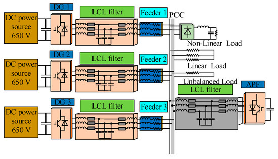
Figure 1.
Diagram of the simulated test setup with three inverters and one active power filter (APF). DG = distributed generators; PCC = point of common coupling; LCL filter = inductive-capacitive-inductive filter; DC power source = direct current power source.
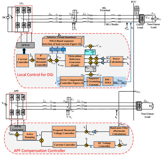
Figure 2.
Proposed hierarchical control of DGs and APF.
Once harmonic power sharing is achieved, it is assumed to have better voltage levels at the DG terminals as well as at the PCC. The synergy between the APF and the DGs is necessary in a secondary control loop if there are still serious voltage distortions at the DG terminals as well as at the PCC; in this case, PCC voltage is used for compensating the THDs of output voltages of DGs. The APF used in this scheme in is based on voltage control that takes the direct PCC voltage and compensates the harmonic voltages of DGs directly according to their rated values, as well as improving the PCC. Therefore, an enhanced control between the DGs and the APF for compensating the PCC voltage is required.
3. Local Control of DG
Power sharing is considered at the primary local control [26,27,28]. The primary control would be accountable not only for minimizing the harmonic circulating currents among the DGs but also for voltage unbalance compensation in the microgrid and the proper adjustment of voltage and frequency deviations according to the regulation of active and reactive power in the microgrid [29]. As can be seen in, the primary control consists of voltage and current control loops, the selective virtual impedance loop using delayed signal cancellation with second-order generalized integrators (DSC-SOGI), the power droop controller and the active and reactive power calculation block, while the secondary loop consists of harmonic current compensation, the voltage and the frequency controller that is described briefly as follows.
3.1. PR Inner Voltage and Current Loops
When there are nonlinear loads in the microgrid, output voltage quality does not remain sinusoidal and contains harmonics that make the system distorted. Therefore, widespread proportional resonant controllers are used for that objective, which deals with dominated harmonics and compensates distorted harmonics. Equations (1) and (2) illustrate the transfer functions for the proportional resonant controllers [27];
where kpω and kpE are the proportional voltage and current controllers respectively.
3.2. Selective Virtual Impedance Using DSC-SOGI in an Islanded Microgrid
Virtual impedances can be employed for improving the load sharing between the DGs as well as for limiting the harmonic unbalance compensation in the paralleled converters [6]. Hence, in this paper, selective virtual impedance using DSC-SOGI is presented in order to accomplish these goals. As depicted in Figure 3, the virtual positive sequence, negative sequence, and harmonic sequence can be derived in the αβ axis as follows [28,29]:
where show the fundamental virtual resistance and inductance for the positive sequence. Likewise, represent fundamental virtual resistance and inductance for the negative sequence. Furthermore, are harmonic virtual resistance and inductance, while h represents the harmonics order of the dominated harmonic components (h = −5, 7, −11, 13, 17 etc.).

Figure 3.
DSC-SOGI virtual impedance.
3.3. Harmonic Power Sharing Compensation Controller
Some circulating current flow may appear, which might cause the system to imbalance when different DGs have diverse load sharing due to unequal feeder impedances and intensive nonlinear loads [30]. To make the system stable and to avoid circulating current flow in the paralleled system, a coordinated control mechanism should be developed for the DGs that can dampen the circulating current into the system and make the DGs have equal power sharing [31]. An example is demonstrated in Figure 4. Generally, the output voltage and current of each DG is first acquired at the central controller and fed into the harmonic sharing compensation effort controller, from where the required compensated current signals are then injected back into the primary local controllers of DGs for the accurate harmonic load sharing.
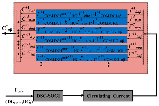
Figure 4.
Harmonic current sharing controller.
Therefore, we use the following Equations to extract the positive sequence, negative sequence and zero sequences of the steady state circulating current [32]:
where Icirc,aj corresponds to the zero sequence, Icirc,bj represents the positive sequence and
Icirc,cj shows the negative sequence circulating current for the jth inverter in the islanded microgrid, respectively.
Once the sequence circulating current is obtained, these harmonic currents are fed into the compensation controller as shown in Figure 4. Mathematically, Equation (7) summaries the system, whereby the difference of the circulating current and the actual current of each DG is multiplied with the compensation gains kiHC [8,13]. After that, the corresponding compensated harmonic currents are passed through a proportional controller, and then fed into multiple P+ resonant controllers for the sake of the supplementary voltage reference set point. Hence, the harmonic current sharing will be shared proportionally. Once the harmonic power sharing is achieved at this level, it is assumed to have better voltage levels at the DG terminals as well as at the point of common coupling [29]. However, if it does not meet the requirement and serious voltage distortions found at the DG terminals as well as at the PCC still exist, then the cooperation of APF with the DGs can be made in the secondary control, which can solve this problem. This is discussed in Section 4.
where represents the compensated component term of ith DG, kiHC denotes the compensation gains and Iiactual. DG shows the actual current of the ith DG and the overall matrix is shown in Equation (7).
3.4. Voltage and Frequency Controller
The voltage and frequency loop improves the droop controller and adjusts the frequency as well as the voltage reference in accordance with the positive sequence active power and reactive power (P+ and Q+) [17]. P*+ and Q*+ are considered as the fundamental positive sequence of active power and reactive power. Vref and ωref define the voltage and frequency references, whereas ωsec and Vsec represent the resulted output frequency and voltage, respectively.
where dpi and dqi are the droop coefficients.
3.5. Droop Control
For achieving the “P” active and “Q” reactive power flow in a steady state conventional manner, the droop control dynamically regulates the voltage amplitude as well as frequency deviations in accordance with active and reactive power [33]. The following are the Equations for the conventional droop active power frequency (P-f) and reactive power voltage amplitude (Q-V) that would mainly be responsible for improving the microgrid stability:
where i is the index that represents each DG unit, P is the measured active power whereas Q is the measured reactive power. Moreover, are the rated frequency and voltages. Similarly, dpi and dqi are the values of active and reactive power droop coefficients.
3.6. Power Calculation
Based on instantaneous reactive power theory [34], the calculation for instantaneous three-phase active power and reactive power corresponding to the values of output voltages and currents can be obtained using:
This instantaneous active and reactive power calculated from Equations (12) and (13) contains both AC and DC elements. These will need to pass through first order low pass filters (LPF) to separate the DC elements and extract the filtered active and reactive powers as below:
4. Design of the Proposed Voltage Controlled APF
The harmonic compensator designed for the recommended APF [19] comprises the DC voltage control loop, fundamental current loop, harmonic voltage compensator control loop and active damping compensator. It is discussed briefly in the following section.
4.1. Active Damping Compensation Control Loop
The active damping loop is implemented in order to stabilize the system and to suppress the resonances. By properly tuning the active damping compensation gain Kd, the stability of the system can be achieved. The output voltage vad for the active damping loop in is given as follows:
where kd represents the active damping compensation loop gain and ic is the capacitor current feedback of the inductive-capacitive-inductive (LCL) filter.
4.2. Current Control Loop and DC Voltage Controller
The proportional integral (PI) controller for the inner control loop was designed in the s-domain and the corresponding controller gains for this PI can be set as follows:
The controller gain kp of the PI controller can be adjusted based on the selected cross over frequency.
To regulate and stabilize the DC voltage, the DC voltage controller takes into account the DC capacitor voltage Vdc and makes a comparison with the DC voltage reference Vdcref to create the active current reference ∇id.
4.3. Harmonic Voltage Control Loop
Resonant controllers have been employed in this control loop, and the corresponding transfer function has been derived in the s-domain which is shown below [35]:
where kresn denotes the gain of the resonant controller, h shows the harmonic order and φ is the phase angle chosen at the resonance frequency.
5. Proposed Control Strategy for the APF and DGs in an Islanded Microgrid
The main control scheme for designing the proposed voltage controlled APF is deduced from [21]. The recommended APF is more suitable for maintaining the DG output voltages corresponding to the PCC harmonic voltages because its control strategy mainly works with converters that are operated in voltage-controlled mode. In, a control strategy for the APF and DGs is discussed. The harmonic PCC voltage can be controlled by taking the direct voltage Vpcc at the PCC even without adopting the load current.
This method leads to a good PCC voltage. The equation for the DG harmonic voltage is:
where Ch defines the feedback and the compensation gain for controlling the harmonics and its values can be adjusted from −1 to ∞. The value of K and its polarity can be adjusted for harmonic compensation of the converter. Normally the gain K is chosen as KVpcch < 0 for harmonic compensation or KVpcch > 0 for harmonic rejection [18,20,36].
To briefly illustrate the control scheme, the proposed flow chart of the hierarchical control plan for the DGs and APF is shown below in Figure 5.
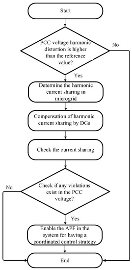
Figure 5.
Flowchart of the proposed hierarchical control of DGs and APF.
At first, the values of output currents of each distributed generation unit DGi are sent to the measurement block in the secondary controller by LBC lines. There, it is checked and compared with the reference values for harmonic current sharing. The required harmonic current signals are then passed through the compensators, where they are sent back to the local controllers of each DG through LBC lines. After harmonic current sharing, the total harmonic distortion of PCC voltage is then checked, as well as the THDs of the output voltages of DGs. The integration of APF with the DGs is required only if our values are not in accordance with IEEE standards. Based on THD voltages error, our proposed APF [21] automatically adjusts the compensation gain, since the harmonic compensator is embedded in its control part, which would try to decrease the THD of the output voltages and improve the PCC voltage up to the nominal values.
THD is the deciding parameter that is used for voltage compensation in the microgrid. While compensating the PCC voltage by DGs, THD of output voltages should not go beyond its maximum value (5%). Therefore, keeping this in mind, THD voltage is chosen as a clue or an indicator for deciding the voltage compensation required for the DGs to limit THD and maintain the PCC voltage as defined by IEEE standards.
6. Simulation Results
First, to illustrate the performance of the considered control mechanism, extensive simulation results have been acquired from three-phase microgrid architecture in an islanded microgrid. The developed islanded microgrid includes three DGs (in a three-phase three-wire system associated with having an LCL filter with a different power rating), one APF and a combination of linear and nonlinear loads connected to the PCC with unequal feeder impedances.
The model is implemented in Simulink/MATLAB to validate the hierarchical control for direct voltage harmonics compensation in microgrids where the voltage controlled APF is enabled. As illustrated in, the APF is directly attached to the PCC. Based on IEEE Standard 519-1992 [5,37] the maximum admissible value of THD voltage at the PCC should be maintained at 5% or less than 5%. Direct voltage compensation is done for the 5th, 7th, 11th and 13th order harmonics with a reference estimation of 1%. Table 1 shows the system parameters used in the simulation [31]. Table 2 lists the control parameters of the system [35]. It is worth noting that the values of the rated power of DGs are different.

Table 1.
System parameters.

Table 2.
Control parameters.
The simulations were performed in various steps, which are explained as follows. In the first step (without harmonic current compensation), only the virtual impedance loop is active, and no harmonic current sharing compensation is activated. Figure 6a shows three-phase DG output voltages and the PCC. It can be realized from Figure 6a that the DG output voltages are almost distortion free and lower than the value of the THD. This illustrates the effectiveness of the droop controllers, the inner loop and the virtual impedance. It also demonstrates a good tracking of voltage reference made by the voltage controller of the power controllers. However, it can be clearly seen that regardless of the distortion free output sinusoidal voltages of DGs, the PCC voltage is considerably distorted due to the mismatched feeder impedances as seen in Figure 7a. The corresponding output DG current waveforms can be seen in Figure 8. It clearly shows that DGs have improper harmonic current sharing before the harmonic compensation is activated as DG3 has a higher current magnitude than that of the other DGs. As a result, it appears that some circulating current exists between the DGs. Therefore, it can be seen that harmonic voltage distortion of the DGs is apparently small in the first step, but the THD of the PCC is higher due to the occurrence of voltage drops across the feeder impedances.

Figure 6.
Voltage waveforms of DGs in various steps for the harmonic compensation from left to right. (a) First step (without harmonic current compensation); (b) second step (with harmonic current compensation); (c) third step (enabling the APF).
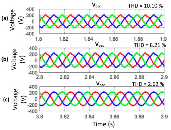
Figure 7.
Voltage waveforms of DGs in various steps for the harmonic compensation from left to right. (a) First step (without harmonic current compensation); (b) second step (with harmonic current compensation); (c) third step (enabling the APF).

Figure 8.
Current waveforms of DGs in various steps for the harmonic compensation from left to right. (a) First step (without harmonic current compensation); (b) second step (with harmonic current compensation); (c) third step (enabling the APF).
In the second step (with harmonic current compensation), the compensation in the sharing of harmonic current among the DGs is discussed. It can be realized in Figure 8. that proper harmonic current sharing is achieved with respect to the DG rated power. Consequently, the output waveform voltages of the DGs are prone to more distortion. However, the PCC voltage is improved considerably. As previously shown in Figure 7, as soon as the harmonic compensation is activated, a small improvement in PCC is observed at the expense of DG output voltages. It can be observed in Figure 8b that due to the harmonic current compensation as well as the PCC, DG1 voltage is severely distorted and at the same time, DG3 output voltage is not even reasonable. This shows that DG1 and DG3 play a leading role in the compensation of PCC voltage. As can be seen in Figure 8a, without implementing the harmonic current compensation, the active and reactive power is not shared due to unequal feeder impedances and nonlinear loads and there exists large circulating current. As soon as the harmonic current sharing is enabled in step two, enhanced current sharing among the DGs can be realized and also proper sharing of active and reactive power can be achieved as it revealed by the comparison of Figure 8a,b and Figure 9a,b. However, the THD of the PCC voltage is still not in the range of International Electrotechnical Commission (IEC) standards. The harmonic distortion at the output of DGs is high. Therefore, in order to improve the power quality, our proposed APF is incorporated with the DGs in step three, which not only improves the power quality Vpcc at the point of common coupling (PCC), but also eliminates the voltage imbalance at the output of the DG terminal. Figure 10 illustrates the circulating current of each DG unit after step two and step three.
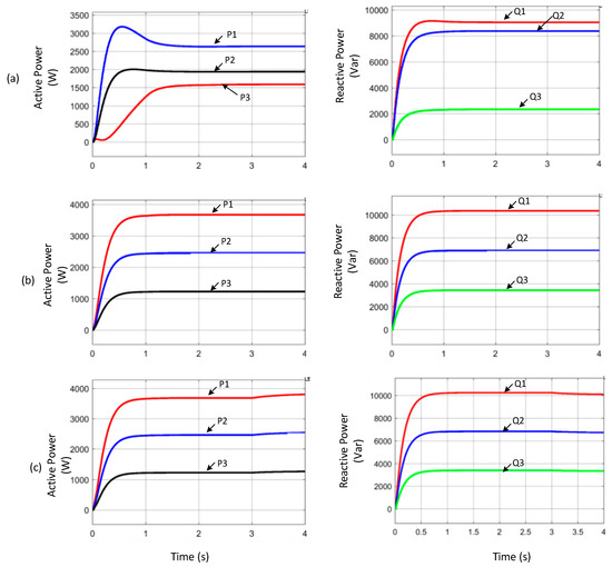
Figure 9.
Power sharing among the DGs. (a) First step (without harmonic current compensation); (b) second step (with harmonic current compensation); (c) third step (enabling the APF). Where P1, P2, P3 is the active power sharing of DG1, DG2 and DG3 respectively. Similarly Q1, Q2, Q3 is the corresponding reactive power sharing of DG1, DG2 and DG3 respectively.
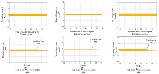
Figure 10.
Reduction in circulating current waveforms of DGs.
In the third step (enabling the coordinated control of APF with DGs), once the voltage controlled APF is energized under the hierarchical coordinated control of DGs and APF, the output voltages of DGs seems to be improved and the PCC voltage is more sinusoidal and cleaner in nature as its THD significantly goes down from 8.30% to 2.30%. Furthermore, the compensated harmonics (5th, 7th, 11th, 13th, 17th, and 19th order) are reduced drastically, as indicated in Figure 11a,b. It is worth noting that due to the harmonic current sharing in step two and moreover, the activation of APF in step three, circulating currents between the DGs has been minimized as shown in step three of Figure 10.
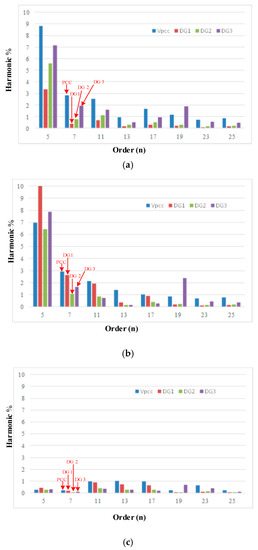
Figure 11.
The frequency spectrum of PCC voltage and output DG voltages of multiple DGs under different steps with and without APF in an islanded microgrid. (a) First step (without harmonic current compensation); (b) second step (with harmonic current compensation); (c) third step (enabling the APF).
To gain a better insight into the power quality of the system, the harmonic spectrums for the three steps are shown in Figure 11a–c, respectively. In light of the harmonic analysis in Figure 11a, the value of the THD of the PCC voltage is initially 10% without applying any harmonic compensation. In step two, by applying the harmonic current compensation, this value of harmonic distortion is then decreased to 8.30% as shown in Figure 11b, which is still not a significant improvement, despite better current sharing being achieved between the DGs.
On the other hand, introducing the APF in the third step reduces the voltage harmonics to an acceptable level. Figure 11c shows that the 5th and 7th harmonic voltages at the PCC are decreased to <1% and the THD is approximately 2.30%, which meets the IEEE standards. Therefore, the APF takes part in compensation rather than the DGs under the coordinated control of DGs and the APF.
It is noteworthy from Table 3 that there is a sharp decrease in the THD of the PCC voltage from 8.30% to 2.30% as soon as the APF is enabled.

Table 3.
Output DG voltages and Vpcc THDs under different conditions.
7. Conclusions
This paper has demonstrated the power quality improvement with load sharing under the hierarchical coordinated control of different DG units and an APF in microgrids. It has been observed that when appropriate load sharing is achieved in the microgrid (considering unequal feeder impedances and different nonlinear loads), the corresponding THDs of the output voltages at DGs and the PCC increased significantly, which does not meet IEEE standards. Therefore, a direct voltage controlled APF is incorporated with the DGs, establishing an appropriate coordinated control scheme to limit the voltage distortion at the DG terminals to an acceptable range. Furthermore, good harmonic sharing is achieved and the voltage harmonics at the DGs and the PCC are met simultaneously, keeping in view the IEEE standards. It has been determined that the voltage control-based scheme for the proposed coordinated control of DGs and the APF is more suitable for microgrid applications. Finally, the proposed method achieves high compensation accuracy as intensive simulation results have demonstrated the hierarchical control scheme.
Author Contributions
H.M.M. and H.L. have contributed to the theoretical approaches, simulation tests, and preparation of the article, and have contributed equally to this work. R.G. provided insight, resources, supervision and analysis. T.Y. and N.A.G. have contributed to the theoretical approaches and preparation of the article. M.H. and A.S. have provided relevant key theoretical and technical suggestions and reviewed the manuscript.
Acknowledgments
The authors would like to thank Yang Han for his kindness, moral support and all the inspiring discussions throughout this project. Special thanks to Chuan Xie and JianXiao Zou to contribute their efforts in reviewing and editing the manuscript. Finally, the authors would also like to thank the anonymous reviewers and editors for their insightful comments and feedback which helped to improve this manuscript.
Conflicts of Interest
The authors declare no conflicts of interest.
References
- Jintakosonwit, P.; Fujita, H.; Akagi, H.; Ogasawara, S. Implementation and performance of cooperative control of shunt active filters for harmonic damping throughout a power distribution system. IEEE Trans. Ind. Appl. 2003, 39, 556–564. [Google Scholar] [CrossRef]
- Henderson, R.D.; Rose, P.J. Harmonics: The Effects on Power Quality and Transformers. IEEE Trans. Ind. Appl. 1994, 30, 3. [Google Scholar] [CrossRef]
- Yazdavar, A.H.; Azzouz, M.A.; El-Saadany, E.F. A Novel Decentralized Control Scheme for Enhanced Nonlinear Load Sharing and Power Quality in Islanded Microgrids. IEEE Trans. Smart Grid 2017, 3053, 2017. [Google Scholar]
- Vandoorn, T.L.; de Kooning, J.D.M.; Meersman, B.; Vandevelde, L. Review of primary control strategies for islanded microgrids with power-electronic interfaces. Renew. Sustain. Energy Rev. 2013, 19, 613–628. [Google Scholar] [CrossRef]
- Saint, B.; Member, S.; Scope, A. Update on IEEE P1547. 7—Draft Guide to Conducting Distribution Impact Studies for Distributed Resource Interconnection. In Proceedings of the 2012 IEEE/PES Transmission & Distribution Conference and Exposition, Orlando, FL, USA, 7–10 May 2012; pp. 1–2. [Google Scholar]
- Hoang, T.V.; Lee, H.H. An Adaptive Virtual Impedance Control Scheme to Eliminate the Reactive-Power-Sharing Errors in an Islanding Meshed Microgrid. IEEE J. Emerg. Sel. Top. Power Electron. 2017. [CrossRef]
- Savaghebi, M.; Jalilian, A.; Vasquez, J.C.; Guerrero, J.M. Secondary control for voltage quality enhancement in microgrids. IEEE Trans. Smart Grid 2012. [Google Scholar] [CrossRef]
- IOutput, U.R.; Chen, Y.; Guerrero, J.M.; Shuai, Z. Fast Reactive Power Sharing, Circulating Current and Resonance Suppression for Parallel Impedance Fast Reactive Power Sharing, Circulating Current and Resonance Suppression for Parallel Inverters Using Resistive-Capacitive Output Impedance. IEEE Trans. Power Electron. 2015, 31, 5524–5537. [Google Scholar]
- He, J.; Li, Y.W.; Guerrero, J.M.; Blaabjerg, F.; Vasquez, J.C. Microgrid reactive and harmonic power sharing using enhanced virtual impedance. In Proceedings of the 2013 Twenty-Eighth Annual IEEE Applied Power Electronics Conference and Exposition (APEC), Long Beach, CA, USA, 17–21 March 2013; pp. 447–452. [Google Scholar]
- Wang, X.; Blaabjerg, F.; Chen, Z.; Guerrero, J.M. A centralized control architecture for harmonic voltage suppression in islanded microgrids. In Proceedings of the IECON 2011—37th Annual Conference of the IEEE Industrial Electronics Society, Melbourne, VIC, Australia, 7–10 November 2011; pp. 3070–3075. [Google Scholar]
- Lee, T.; Li, J.; Cheng, P. Discrete Frequency Tuning Active Filter for Power System Harmonics. IEEE Trans. Power Electron. 2009, 24, 1209–1217. [Google Scholar]
- Lee, T.; Cheng, P.; Akagi, H.; Fujita, H. A Dynamic Tuning Method for Distributed Active Filter Systems. Control 2008, 44, 612–623. [Google Scholar] [CrossRef]
- Lorzadeh, I.; Abyaneh, H.A.; Savaghebi, M.; Lorzadeh, O.; Bakhshai, A.; Guerrero, J.M. An enhanced instantaneous circulating current control for reactive power and harmonic load sharing in islanded microgrids. J. Power Electron. 2017, 17, 1658–1671. [Google Scholar]
- Wang, X.; Li, Y.W.; Member, S.; Blaabjerg, F. Virtual-Impedance-Based Control for Voltage-Source and Current-Source Converters. IEEE Trans. Power Electron. 2015, 30, 7019–7037. [Google Scholar] [CrossRef]
- Han, Y.; Shen, P.; Zhao, X.; Guerrero, J.M. An Enhanced Power Sharing Scheme for Voltage Unbalance and Harmonics Compensation in an Islanded Microgrid. IEEE Trans. Energy Convers. 2016, 31, 1037–1050. [Google Scholar] [CrossRef]
- Wada, K.; Fujita, H.; Akagi, H. Considerations of a shunt active filter based on voltage detection for installation on a long distribution feeder. IEEE Trans. Ind. Appl. 2002, 38, 1123–1130. [Google Scholar] [CrossRef]
- Han, Y.; Shen, P.; Zhao, X.; Guerrero, J.M. Control Strategies for Islanded Microgrid using Enhanced Hierarchical Control Structure with Multiple Current—Loop Damping Schemes. IEEE Trans. Smart 2015, 99, 1–15. [Google Scholar] [CrossRef]
- Zhao, X.; Meng, L.; Xie, C.; Guerrero, J.M.; Wu, X. A Unified Voltage Harmonic Control Strategy for Coordinated Compensation with VCM and CCM Converters. IEEE Trans. Power Electron. 2017, 8993, 1. [Google Scholar] [CrossRef]
- Munir, H.M.; Zou, J.; Xie, C.; Li, K.; Zhao, X.; Guerrero, J.M. Direct Harmonic Voltage Control Strategy for Shunt Active Power Filter. In Proceedings of the IECON 2017—43rd Annual Conference of the IEEE Industrial Electronics Society, Beijing, China, 29 October–1 November 2017; Volume 8, pp. 5–10. [Google Scholar]
- He, J.; Member, S.; Li, Y.W.; Munir, S. Voltage-Controlled DG—Grid Interfacing Converters. IEEE Trans. Ind. Electron. 2012, 59, 444–455. [Google Scholar] [CrossRef]
- Wang, X.; Blaabjerg, F.; Chen, Z. Synthesis of variable harmonic impedance in inverter-interfaced distributed generation unit for harmonic damping throughout a distribution network. IEEE Trans. Ind. Appl. 2012, 48, 1407–1417. [Google Scholar] [CrossRef]
- Hashempour, M.M.; Savaghebi, M.; Vasquez, J.C.; Guerrero, J.M. A control architecture to coordinate distributed generators and active power filters coexisting in a microgrid. IEEE Trans. Smart Grid 2016, 7, 2325–2336. [Google Scholar] [CrossRef]
- Munir, H.M.; Zou, J.; Xie, C.; Li, K. Direct Harmonic Voltage Control Strategy of Shunt Active Power Filters Suitable for Microgrid Applications. J. Power Electron. 2019, 19, 265–277. [Google Scholar]
- He, J.; Liang, B.; Li, Y.W.; Member, S. Simultaneous Microgrid Voltage and Current Harmonics Compensation Using Coordinated Control of Dual-Interfacing-Converters. IEEE Trans. Power Electron. 2017, 8993, 2647–2660. [Google Scholar] [CrossRef]
- He, J.; Li, Y.W.; Blaabjerg, F. An enhanced islanding microgrid reactive power, imbalance power, and harmonic power sharing scheme. IEEE Trans. Power Electron. 2015. [Google Scholar] [CrossRef]
- Ding, G.; Wei, R.; Zhou, K.; Gao, F.; Tang, Y. Communication-less harmonic compensation in a multi-bus microgrid through autonomous control of distributed generation grid-interfacing converters. J. Mod. Power Syst. Clean Energy 2015, 3, 597–609. [Google Scholar] [CrossRef]
- Savaghebi, M.; Jalilian, A.; Vasquez, J.C.; Guerrero, J.M. Autonomous voltage unbalance compensation in an islanded droop-controlled microgrid. IEEE Trans. Ind. Electron. 2013, 60, 1390–1402. [Google Scholar] [CrossRef]
- Karimi-Ghartemani, M.; Khajehoddin, S.A.; Jain, P.K.; Bakhshai, A.; Mojiri, M. Addressing DC component in pll and notch filter algorithms. IEEE Trans. Power Electron. 2012. [Google Scholar] [CrossRef]
- Ranjbaran, A.; Ebadian, M. A power sharing scheme for voltage unbalance and harmonics compensation in an islanded microgrid. Electr. Power Syst. Res. 2018, 155, 153–163. [Google Scholar] [CrossRef]
- Wang, X. A Novel Model Predictive Control Strategy to Eliminate Zero-Sequence Circulating Current in Paralleled Three-Level Inverters. IEEE J. Emerg. Sel. Top. Power Electron. 2019. [Google Scholar] [CrossRef]
- Li, H.; Han, Y.; Yang, P.; Xiong, J.; Wang, C.; Guerrero, J.M. A proportional harmonic power sharing scheme for hierarchical controlled microgrids considering unequal feeder impedances and nonlinear loads. In Proceedings of the 2017 IEEE Energy Conversion Congress and Exposition, Cincinnati, OH, USA, 1–5 October 2017. [Google Scholar]
- Pan, C.T.; Liao, Y.H. Modeling and control of circulating currents for parallel three-phase boost rectifiers with different load sharing. IEEE Trans. Ind. Electron. 2008, 55, 2776–2785. [Google Scholar]
- Han, Y.; Li, H.; Shen, P.; Coelho, E.A.A.; Guerrero, J.M. Review of Active and Reactive Power Sharing Strategies in Hierarchical Controlled Microgrids. IEEE Trans. Power Electron. 2017, 32, 2427–2451. [Google Scholar] [CrossRef]
- Rolim, L.G.B.; da Costa, D.R.; Aredes, M. Analysis and software implementation of a robust synchronizing PLL circuit based on the pq theory. IEEE Trans. Ind. Electron. 2006. [Google Scholar] [CrossRef]
- Munir, H.M.; Zou, J.; Xie, C.; Guerrero, J.M. Cooperation of voltage controlled active power filter with grid-connected DGs in microgrid. Sustainability 2018, 11, 154. [Google Scholar] [CrossRef]
- He, J.; Li, Y.W.; Blaabjerg, F. Flexible Microgrid Power Quality Enhancement Using Adaptive Hybrid Voltage and Current Controller. IEEE Trans. Ind. Electron. 2014, 61, 2784–2794. [Google Scholar] [CrossRef]
- Basso, T. IEEE 1547 and 2030 Standards for Distributed Energy Resources Interconnection and Interoperability with the Electricity Grid IEEE 1547 and 2030 Standards for Distributed Energy Resources Interconnection and Interoperability with the Electricity Grid. Available online: https://www.nrel.gov/docs/fy15osti/63157.pdf (accessed on 15 May 2015).
© 2019 by the authors. Licensee MDPI, Basel, Switzerland. This article is an open access article distributed under the terms and conditions of the Creative Commons Attribution (CC BY) license (http://creativecommons.org/licenses/by/4.0/).