Article

Parametric Study of an Air Charged Franchot Engine with Novel Hot and Cold Isothermalizers

School of Engineering, Institute for Energy Systems, University of Edinburgh, Edinburgh EH9 3DW, Scotland, UK
*
Author to whom correspondence should be addressed.
Inventions 2017, 2(4), 35; https://doi.org/10.3390/inventions2040035
Submission received: 19 October 2017 / Revised: 23 November 2017 / Accepted: 1 December 2017 / Published: 5 December 2017

Abstract

:
The Stirling engine is an external combustion engine that uses heat exchangers to enhance the addition and removal of energy. This makes the engine power-dense but expensive, less efficient and complicated. In this contribution, the Stirling engine based on the Franchot engine has novel cylindrical fins working as isothermalizers to improve heat transfer without the complications of heat exchangers. Enhancing the power density by isothermalizing work spaces is compared to the bare cylinder optimized by varying the phase angle. The theoretical analysis shows that both the adiabatic and isothermal fins increase the power and efficiency, achieving the Curzon and Ahlborn efficiency at the maximum power point. In comparison to the phase angle method, the finned engine resulted in much lower gas mass flow rate, which leads to a reduction in the regenerator pumping and enthalpy losses. Thus, the Stirling engine has the potential to be simple, cheap, efficient and power-dense, and thus can be used effectively for different applications.

Graphical Abstract

1. Introduction

In internal combustion engines, air and fuel are mixed and burned inside the working cylinders and thus, the temperature of the mixture rises very fast. The exhausted gas is discharged to the atmosphere requiring no heat exchanger. In contrast, Stirling engines exchange the heat with the working gas through finite surfaces, which limits the heat transfer. Many techniques have been used to increase the heat transfer and are classified as follows.

1.1. Plain Cylinder

In plain cylinder Stirling engines, heat is exchanged through displacer cylinder end plates [1,2,3]. A light displacer that has low thermal conductivity shuttles the gases between the hot and cold sides. However, the cold side has a larger surface area because the power cylinder wall is located on the cold side. The heat transfer can be enhanced by increasing the end plate areas of the displacer-containing cylinder. This will increase the size of the engine, limiting its applications to low-power applications. Enhancing the power by increasing the temperature difference is possible but requires an increase of the displacer length. Accordingly, high-temperature high-power engines have the large wall area of the displacer-containing cylinder, which is not participating in heat addition or rejection. Moreover, a long displacer increases the volume and weight of the Stirling engine. Low-temperature difference (LTD) engines reported by Kongtragool et al. [4] effectively reduce the wall area by using a short displacer with relatively large diameter. Hence the plain cylinder method is suitable for low-temperature low-power engines, which are characterised by small displacer stroke, low operating speed, simplicity and low-cost technologies and materials [5]. However, the advantages of LTD Stirling engines are balanced by lower efficiencies and power densities. The moderate temperature difference (MTD) Stirling engine reported by [6] has low heat transfer area and a long displacer. It needs concentrated heating and cooling in small areas, which reduces the in-cylinder heat transfer. Figure 1 shows the geometry differences between a gamma type LTD and MTD with plain cylinders.
Daoud and Friedrich [7] reported a novel Franchot engine design in which the heat transfer area was extended to the whole cylinder wall area, which allows the use of high temperatures. In addition, they increased the phase angle to allow faster speeds and hence increased the heat transfer. Unfortunately, the increase in the heat transfer is not in the same order as the increase in the speed.

1.2. Heat Exchanger

In general, the Stirling machine with bare cylinders has poor heat transfer [8,9,10]. To increase the heat transfer, additional heat exchangers that are connected in series to the gas circuit are needed [11]. The heat exchangers increase the heat transfer area and make it possible to operate at high power densities. In reality, they are responsible for increasing gas friction losses and dead volume, which should ideally be zero [12]. The heat exchangers are particularly responsible for increasing the Stirling engine complexity and cost [8]. The most commonly used heat exchangers with Stirling engines are reported in [13,14,15]. However, additional heat exchangers do not lead to an increase in the maximum power efficiency [16].
A Stirling engine with heat exchangers has a thermodynamic cycle that differs from the ideal one. As the speed increases, the isothermal expansion and compression processes become more adiabatic [8,13,17], which produces lower cycle work and efficiency than the isothermal processes [9,18,19]. The efficiency is even worse than the ideal adiabatic efficiency due to the non-adiabatic cylinders and non-isothermal heat exchangers that increase the irreversibilities [20,21,22]. Hence the thermodynamic processes are better described by polytropic processes. Figure 2 clearly shows the differences between the isothermal and adiabatic processes on the cycle work.

1.3. Isothermalizer

Enhancing the in-cylinder heat transfer will increase the power and efficiency by modifying the machine internal heat transfer area without adding to the dead volume [8,23]. The improvement in heat delivery without increasing the dead volume is called isothermalization [11]. Bergman et al. [11] claimed there will be a geometrical limitation for increasing the heat transfer by an isothermalizer. Carlson et al. [10] numerically showed that increasing the in-cylinder heat transfer towards isothermal in the Stirling cycle machines with heat exchangers will increase their efficiency to 100% of Carnot efficiency. However, at the maximum power point, the engine efficiency cannot exceed the Curzon and Ahlborn limit [24] where the working gas temperature does not equal the cylinder wall temperature. The temperature difference helps by increasing the heat transfer, which reduces the thermal load on the isothermalizer and hence the gas friction losses in comparison to the heat exchangers. The isothermalizers differ from the external heat exchangers in that the heater and cooler are within the expansion and compression spaces and not in series with them. Accordingly, the expansion and compression processes are neither isothermal nor adiabatic; they are polytropic. Figure 3 shows the differences between the isothermal and polytropic process on the cycle work.
One of the known methods to isothermalize the working space is using interleaving fins. The fins increase the heat transfer area by creating augmentations in the plain cylinder end plates. However, the heat transfer changes with the piston position [25]. When a finned displacer or piston compresses, the conjugate fins get closer to each other allowing the heat transfer to be the largest. However, when a finned piston or displacer expands the distance between the fins gets larger decreasing the heat transfer. Hauser et al. [26] designed an apparatus to calculate the heat transfer in an engine with layer type interleaving fins. He found an improvement in the heat transfer in comparison to the bare cylinder. W. Martini [25] argued the best interleaving fins are the nesting cones. However, using long cones will increase gas friction. Benson [27] patented multiple concentric cylinders for isothermalizing the working spaces in external combustion heat engines including the Stirling engine. However, this will increase the dead volume due to the clearance between the opposite concentric plates at full compression state.
Others suggested heat injection in both the cold and hot chambers, which is analogous to the internal combustion engines. Siegel et al. [28] patented heat injectors for the Stirling engine, which requires external heat exchangers, thermal fluid, injectors and thermal liquid pumps. This complicates the Stirling machines and increases the number of moving parts. Smith et al. [29] suggested a mechanism to separate the thermal fluid from the working gas in the double acting Franchot-Stirling machines. Their design required the use of 4 pumps and 4 external heat exchangers. In a liquid piston Franchot engine [30], the hot and cold liquid pistons are reheated and re-cooled and then injected into the hot and cold spaces respectively. So far, the Stirling engine isothermalizers have not been deployed with solid pistons because of the geometry limitation and complex fin design.
In this contribution, a simple and novel isothermalizer for the Franchot engine will be presented. The engine is directly heated and cooled with a phase angle set to 90°. A parametric study comparing the new design to the bare engine shows the potential improvements. The study aims to present a Franchot engine that has the potential to achieve higher power density with reduced losses compared to previous designs.

2. Materials and Methods

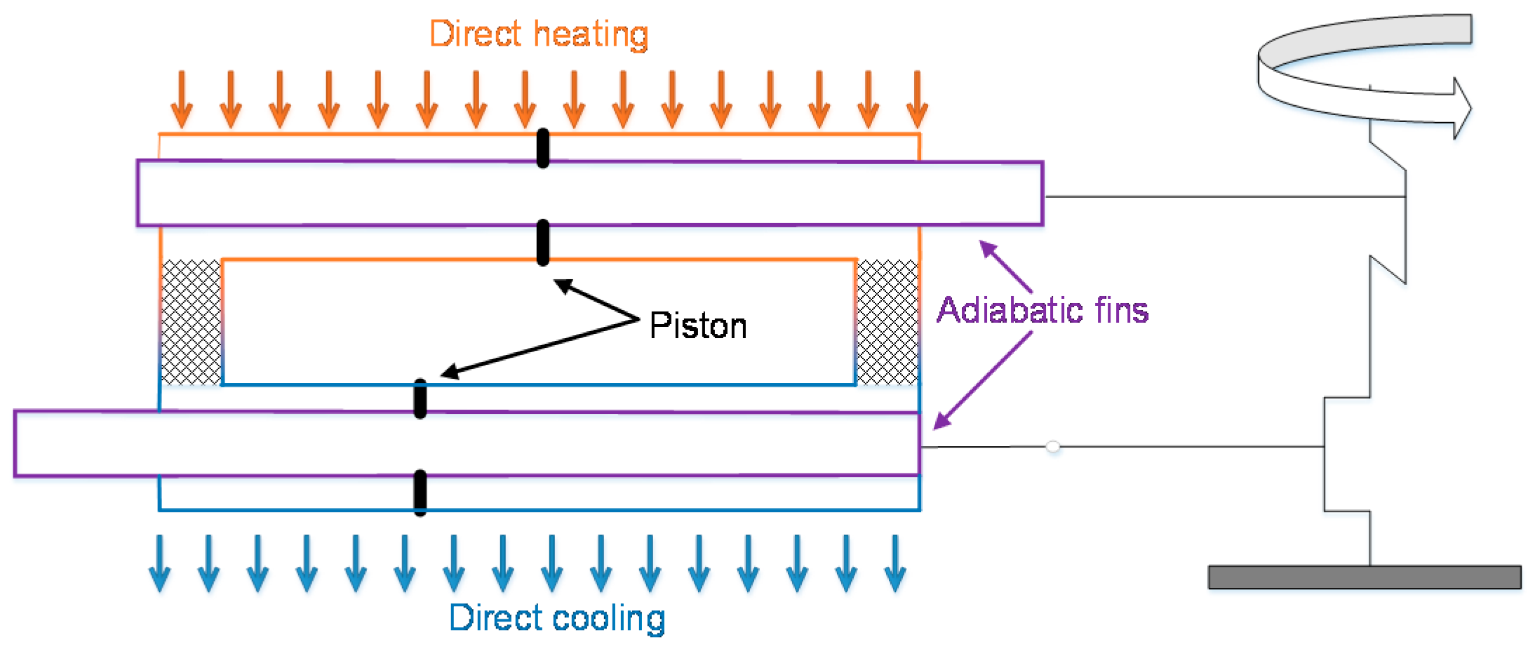
2.1. Isothermalizing the Franchot Engine

The Franchot engine is a double acting Stirling engine that uses only two pistons. The phase angle can be freely controlled and each cylinder is either hot or cold, which eliminates the shuttle and axial conduction losses [31].
The connecting rods that link the engine pistons to the crank must be designed to withstand the forces acting on them to avoid buckling. However, for a double acting Franchot engine (see, for example, Figure 1 in [7]) the connecting rods will be inside the swept volume of one half of the engine and will thus influence the engine behavior. An increase in the connecting rod diameter will reduce the hydraulic diameter, which increases the heat transfer per volume, thus acting like an internal fin although it has unheated and uncooled surfaces (see Figure 4).
According to the definition, the adiabatic fin, which is externally insulated, has a total heat flow equal to zero:
  Q f ˙ =   h A f ( T f T g ) = 0
hence
  h A f T f =   h A f T g
where h, Af, Tf and Tg are the coefficient of heat transfer, fin area, fin temperature and gas temperature, respectively.
The fluctuation in the connecting rod temperature is ignored because of the higher cp × m of the stainless steel rod in comparison to air. Hence the fin temperature is supposed to be constant during a cycle. So the average temperature of the adiabatic fin can be calculated as:
T f =   h A f T g   h A f
The disadvantages of this configuration are the heavy and long connecting rod, the need for sealing each rod from both sides and the thermal insulation of at least the hot piston connecting rod from the air. However, the double-ended rod configuration results in symmetrical swept volumes, unlike the traditional single-ended double-acting engines.
Using heated and cooled internal fins will increase the heat transfer area in addition to the reduction in hydraulic diameter. While it is possible to cool the cold connecting rod as it can be directly exposed to the ambient air, heating the reciprocating rod in the expansion spaces requires a complex configuration. Figure 5 shows another way for heating and cooling the internal fins.
In this single-ended configuration, the connecting rods are linked to the piston from one side and have small diameters that are assumed to not affect the heat transfer or the swept volume. The connecting rod guides can then be sealed from one side and the total engine length is shortened.
Both the adiabatic and isothermal fins have fixed hydraulic diameter and varying heat transfer area over a cycle based on piston locations that are included in the model.

2.2. Mathematical Modelling

The study is based on a second order model derived in a previous contribution for the Franchot engine [7]. The model assumes an ideal Franchot engine with polytrophic expansion and compression processes and ideal regenerator. The current study uses the second order model to consider the gas friction losses in the expansion and compression spaces. With the isothermalizers, the gas contact area is becoming larger and the gas friction loss can affect the power generation and efficiency.
The Franchot engine consists of two alpha engines with 2 separate gas circuits. The pressure variation in each gas circuit is:
p ˙ = p ( v e ˙ T r e + v c ˙ T c r ) + R c p ( Q e ˙ T r e + Q c ˙ T c r ) v e γ T r e + V r T r + v c γ T c r
where v , T and Q ˙ denote the volume, temperature and heat flow rate in the working spaces respectively and subscript e ,   r   and   c indicates the expansion, regeneration and compression space, respectively.
The engine power is calculated for the Franchot engine as
P = 2   p ( v e ˙ + v c ˙ ) × f
where f is the frequency.
External irreversibility is considered through the heat addition and removal, which are calculated from the Newton’s law of cooling [32]:
Q e ˙ = h A Δ T
where h is calculated using Toda et al.’s [33] heat convection correlation, which was experimentally obtained for the swept volume of an air charged Stirling engine with stroke to bore ratio of 1.75 and for a wide range of Reynolds numbers (1500–40,000). In comparison to the heat transfer correlations that can be used with the heat exchangers of the Stirling engine [34], Toda et al. correlation is tailored for heat transfer inside the swept volume of Stirling engines where variable volume, variable pressure and oscillatory flow with wide range of Reynolds’ numbers can exist. The correlation, which holds for Reynolds numbers between 1000 and 100,000 is:
h e = 0.042 D h 0.42 v 0.58 p 0.58 T 0.19 h c = 0.0236 D h 0.47 v 0.53 p 0.53 T 0.11
where ΔT, Dh, he and hc are the temperature differences between the working gas and cylinder wall, hydraulic diameter, convective heat transfer during the expansion and convective heat transfer during the compression.
The pressure loss in the expansion and compression cylinders is calculated separately from the Zhao correlation for oscillatory turbulent pipe flow [35]. This correlation is valid for a range of stroke to bore ratios of 53.4–113.5 and kinetic Reynolds number of 81–540, which is equivalent to a maximum Reynolds number of 2162–30,645 or an average Reynolds number of 1376–19,509:
Δ p = 2 ρ U m a x 2 L X m ( 76.6 ( 2 D h R e m a x X m ) 2 + 0.40624 )
The power loss in each cylinder is calculated from:
P p = Δ p × v ˙
where v ˙ is the volumetric flow rate of the working gas.
The model is implemented in Matlab/Simulink and solved using the Runga-Kutta method with a time step of 10−4 s. Figure 6, Figure 7, Figure 8 and Figure 9 have Reynolds numbers within the range 1465–15,500 and Figure 10 has a minimum of 734 for the adiabatic finned engine and a maximum of 24,530 for the bare cylinder engine in which the friction losses are ignored.

3. Results and Discussion

All results use the reference engine parameters listed in Table 1 unless otherwise stated. Both the gas friction loss in the working cylinders and modified heat transfer coefficient with Dh are considered.

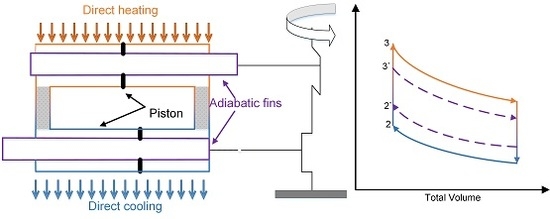
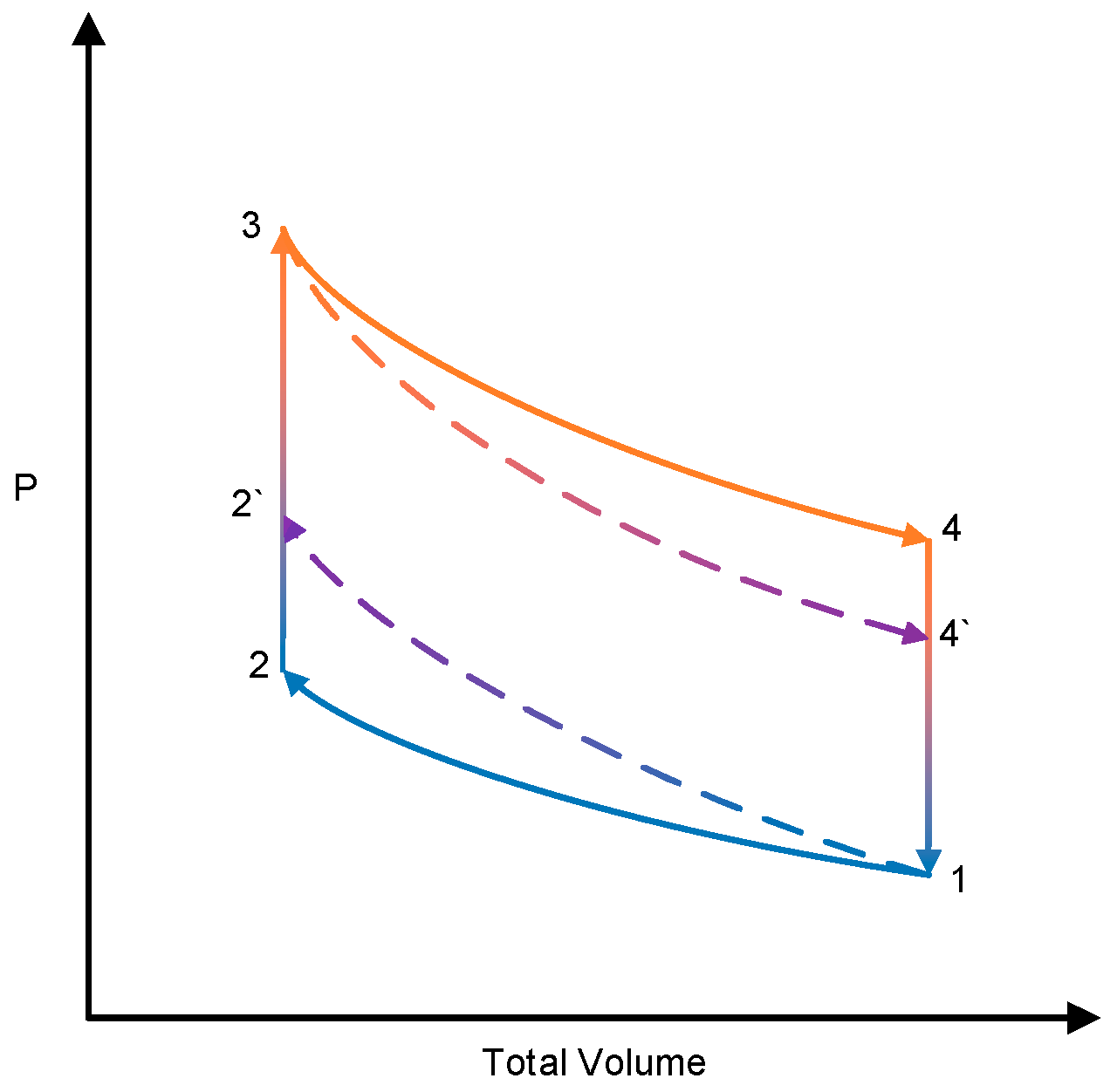
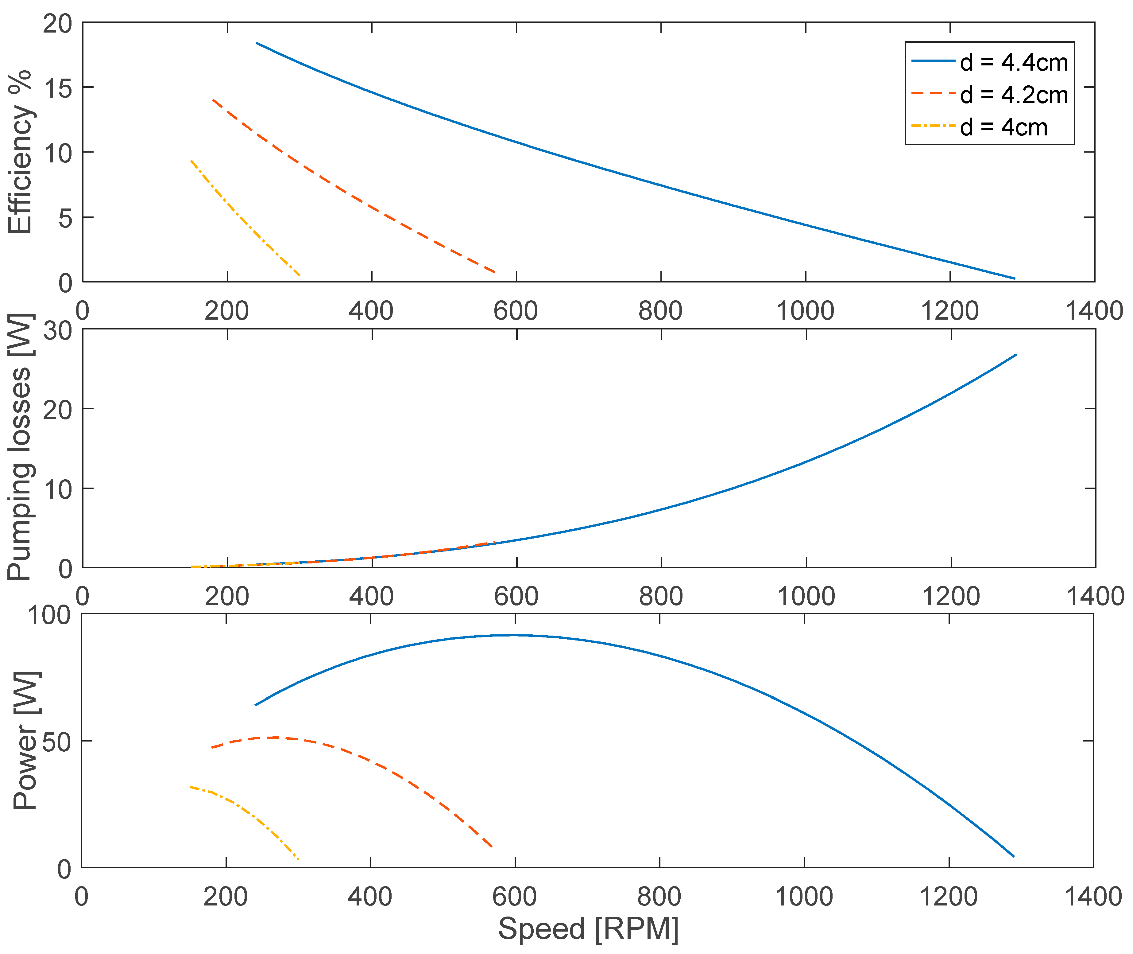
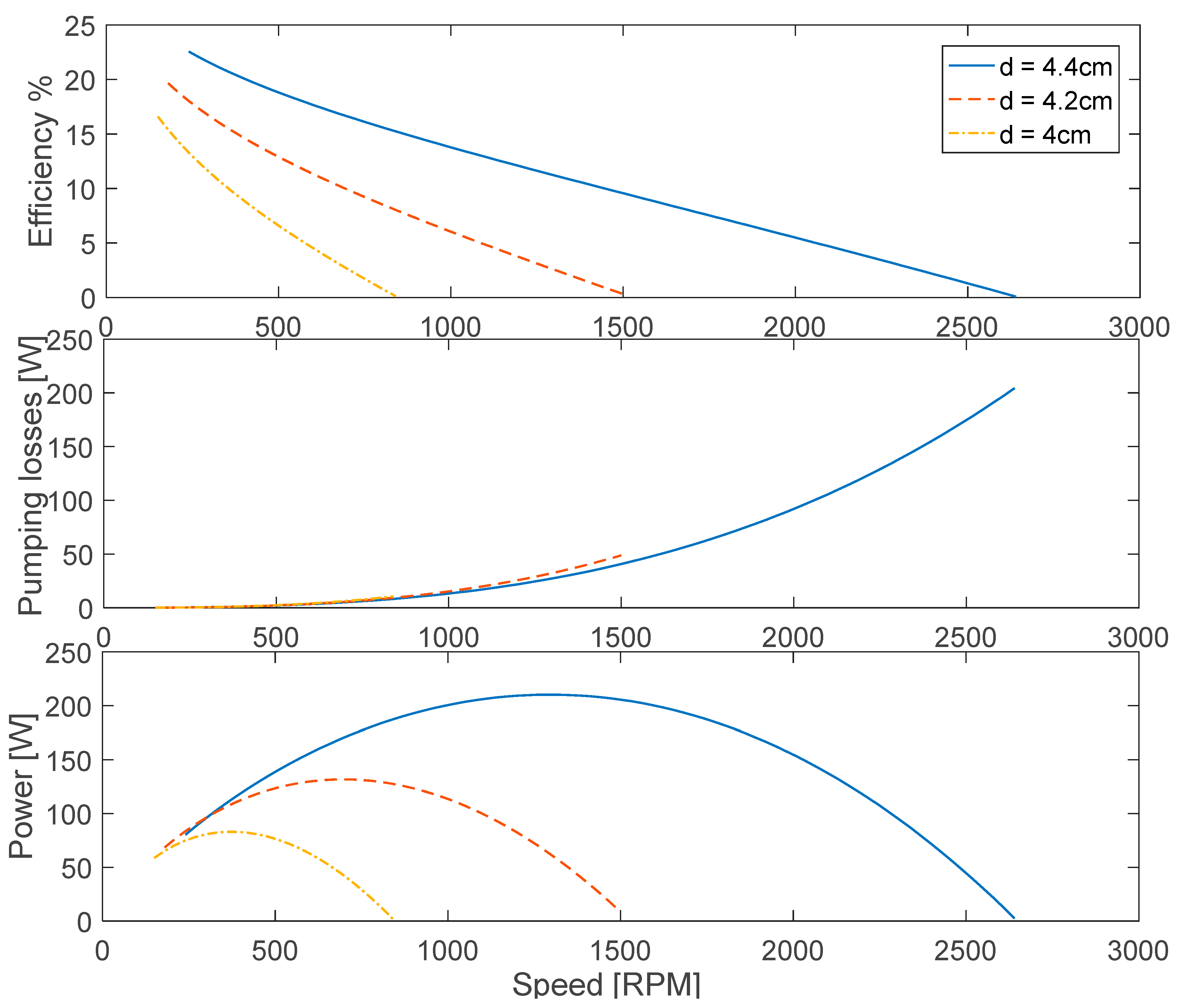
3.1. Influence of the Adiabatic Fin

Figure 6 shows the power increasing with the speed increases until it reaches a maximum. Although no change has been made to the outer cylinder, the power increased as a function of the connecting rod diameter, which means more energy has been exchanged to the working gas. This can be explained by the increase in heat transfer rate per volume due to the decrease in the hydraulic diameter. The power dropped with the speed after the maximum because of the inadequate heat transfer at high speeds and the increase in friction.
Increasing the fin diameter causes the hydraulic diameter to decrease allowing more energy to be exchanged per volume of gas. This increases the efficiency at the given speed and moves the maximum power point to larger speeds.
The gas friction losses increase faster than the power. However, they can be ignored up to the maximum power point.

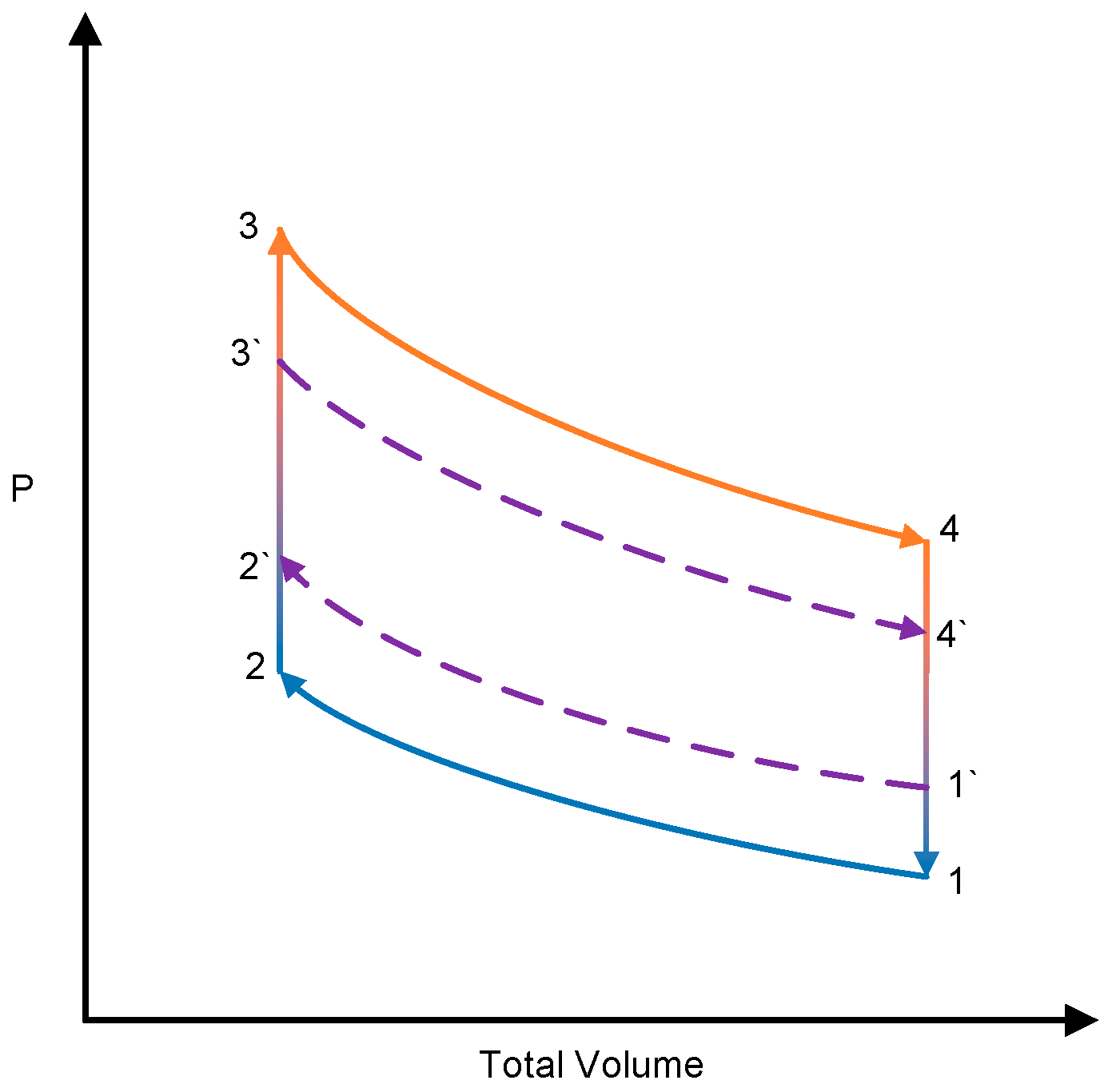
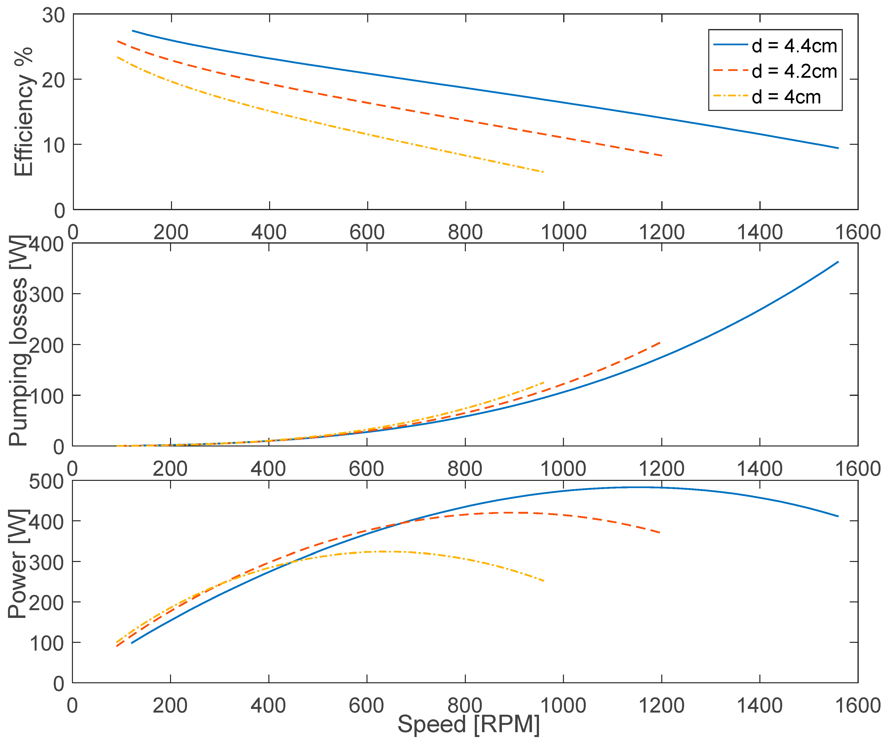
3.2. Influence of the Isothermal Fins

The influence of changing the internal cylinder diameter on the performance of the Franchot engine with isothermal fins is shown in Figure 7.
The power increases with increasing speed until reaching a maximum before dropping to zero. In comparison to the adiabatic rod method, the power is increased by a factor more than 2 at the maximum. The increase can be attributed to the increase in the heat transfer rate due to the participation of the internal cylinder area and the increase in the engine speed.
Due to the same shear area, the gas friction losses for both the adiabatic and isothermal internal cylinders at each single speed was found unaffected by the configuration. However, the power loss due to gas friction is larger in the isothermal configuration due to the higher working speed but it is still negligible up to the maximum power point.
Figure 8 shows the influence of doubling the working cylinder diameter for different internal cylinders on the performance of the Franchot engine with speed.
It shows an increase in the power without affecting the efficiency or the speed compared to the results in Figure 7. The power is enhanced linearly with total heat transfer surfaces for the same speed range. The gas friction loss increased linearly with the rubbing area. However, the 10 cm diameter engine represents dual 5 cm engines but with slightly larger surface due to the internal cylinder surface. This increases both the power and friction losses by a factor slightly larger than 2 with doubling the external diameter and keeping the hydraulic diameter unchanged.
A further increase in the diameter will increase the power, which requires increasing the connecting rods diameters. Hence, it might not be possible if the connecting rod diameter is on order of the hydraulic diameter. However, the number of connected rods can be increased according to the Euler equation for determining the critical buckling load on struts, which is written as:
F m a x = π 2 E I ( k L ) 2
where, E, I, k and L are the modulus of elasticity, second moment of area, effective length factor and unsupported length of the connecting rod, respectively.
The effect of doubling the stroke on the performance of the Franchot engine is shown in Figure 9.
Although the area is doubled, the generated power of the 100 cm stroke is more than twice of the 50 cm stroke. This is because of the higher heat transfer rates due to doubling of the linear velocity. The power improvement for an internal diameter of 4cm is better than the power for 4.2 cm and 4.4 cm in comparison to the 50 cm stroke. It is also noticeable that the maximum power point shifted to higher speeds for the 4 cm and 4.2 cm, while the maximum power speed for the 4.4 cm is nearly unaffected. This can be attributed to the gas friction loss that resists the motion. Interestingly, it is important to consider gas friction loss in long strokes even at the maximum power point. For d = 4.4 cm the gas friction loss is 152 W, which is comparable to the indicated power of 483 W. Therefore, using multiple cylinders or enlarging the diameter instead of elongating the cylinder can be a suitable alternative to increase the power and reduce the pumping losses. In addition to that, long engine cylinders and cranks are hard to implement.

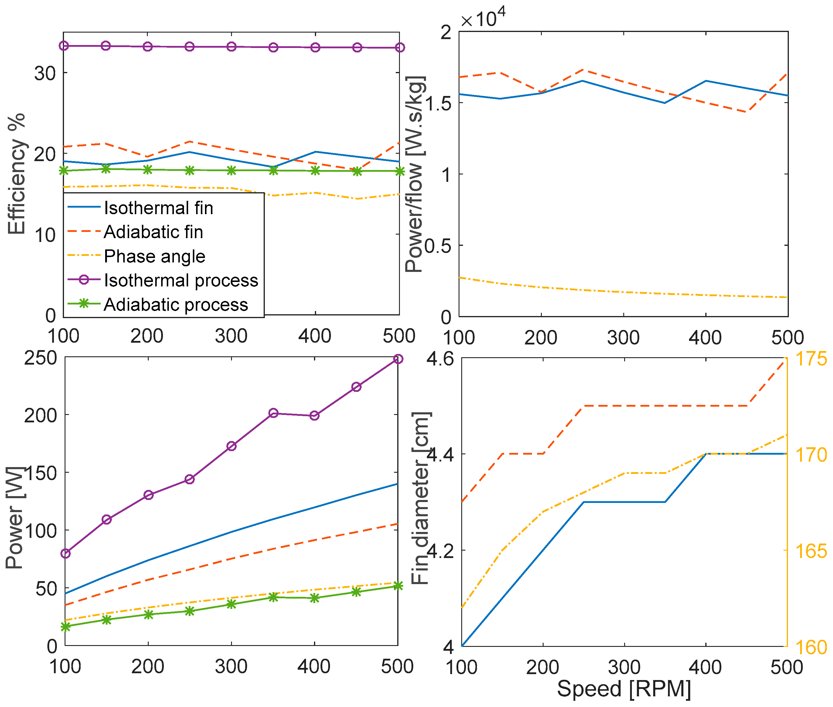
3.3. Optimised Response

Figure 10 shows the optimised response of the system at the maximum power point for three different design parameters: phase angle for plain cylinder and diameter for both adiabatic and isothermal fin. The response of the ideal isothermalizer that has ideal expansion and compression processes and the ideal adiabatic engine in which the heaters and coolers are isothermal and the expansion and compression are adiabatic are shown for comparison. Both the ideal isothermal and adiabatic engines have the same swept volume as the isothermal finned engine. The optimisation was performed manually until the maximum power is reached for the speed range 100–500 rpm. Each single speed, phase angle and connecting rod diameter were changed manually with a step size of 50 rpm, 1 degree and 1 mm respectively. The adiabatic engine was optimized for the maximum power by increasing its regenerator dead volume with a step size of 10−5 m3. The step sizes are believed to be responsible for the roughness in the generated figures.
It is shown that adding fins is superior to the phase angle control method [7] in terms of power and efficiency. The engine with fins works closer to the Curzon efficiency at the maximum power than the phase angle method. In addition the power obtained is higher for the isothermal fin than the bare engine controlled by the phase angle. That is expected since the fins increase the heat transfer and heat transfer area. While the phase angle matches the heat transfer to the power.
It is also shown that cylindrical fin size increases with speed. This is due to the nonlinear increase of the heat transfer in comparison to the swept volume. The fin diameter increases to compensate the increase in the heat required at higher speed by decreasing the hydraulic diameter. It is interesting that the hydraulic diameter of the isothermal rod is larger than that of the adiabatic rod, which eases adding the connecting rods.
In comparison to the ideal isothermalizers, the engine with isothermal fins has an average 43% lower power, which is close to the ratio of Curzon and Carnot efficiencies. This means the engine with the isothermal fines has the maximum possible power density at the maximum power point given that the isothermal engine is impossible to achieve. In the same regard, the ideal adiabatic engine has lower power and efficiency than both the isothermal and adiabatic finned engine. On average the isothermal finned engine produces 2.75 times the power of the ideal adiabatic engine, even though the difference between the efficiencies is small. Thus, the engine would have the potential for power generation and efficiency improvement.
In comparison to the isothermalizer method, the phase angle method resulted in a much lower power to mass flow rate, which increases regenerator losses. However, using an isothermalizer fixes the power to mass flow rate to a constant value by decreasing the swept volume, which allows higher power capabilities at higher speeds.
Technically, the bare cylinder design has larger hydraulic diameter and simple disk shape pistons that ease the sealing of the connecting rods and pistons. Thus, it has the potential to use different working gases due to the small gas leakage through the small rod seals. The adiabatic finned engines have larger and twice the number of connecting rod seals. This increases gas leakage, which makes it harder to trap different working gases so that the engine might only be possible with air as working fluid. The isothermal finned engine has annulus shaped pistons, which requires the sealing of both internal and external surfaces between the fin and the external cylinder and increases the internal gas leakage between the engine chambers. Sealing the connecting rods of the isothermal finned engine might be difficult due to the small hydraulic diameter and the number of connecting rods. In addition to that, in the finned engine higher heat transfer rates compared to the bare cylinder will increase the thermal loads on the cylinders thus requiring a better external heat exchanging mechanisms.

4. Conclusions

Performance investigations are done for both the bare and finned Franchot engine taking into account the gas friction in the compression and expansion cylinders. The power and efficiency were improved for using fins and the Curzon and Ahlborn efficiency is achieved regardless of the friction losses once it is optimized at each single speed. It is shown that the gas friction losses in the compression and expansion spaces can be ignored for short strokes at the maximum power point.
Changing the diameter cannot be done for each speed once the engine is manufactured. This can be considered a disadvantage in comparison to the phase angle control technique. Adjusting the phase angle improves the power density and efficiency without the complexity of the isothermalizers but without reaching the Curzon efficiency in most cases. A phase angle slightly larger than 90° can be used with some attention to the regenerator losses as it increases the mass flow rate. However, the finned engine is superior to the adiabatic engine in terms of the power density and hence the regenerator losses. Large phase angles are highly recommended if large hydraulic diameters are needed. This eases the addition of the connecting rods and reduces the number of required, duplicated engines to achieve a certain power.

Acknowledgments

The authors would like to thank the British Council-HESPAL for the Ph.D scholarship for Jafar M. Daoud.

Author Contributions

Jafar M. Daoud and Daniel Friedrich developed the concept of the isothermalizer. Jafar M. Daoud developed the Matlab/Simulink model of the Franchot engine and ran the simulations. Both authors discussed the results and wrote the paper.

Conflicts of Interest

The authors declare no conflict of interest.

References

  1. Kongtragool, B.; Wongwises, S. A four power-piston low-temperature differential Stirling engine using simulated solar energy as a heat source. Sol. Energy 2008, 82, 493–500. [Google Scholar] [CrossRef]
  2. Kongtragool, B.; Wongwises, S. Performance of a twin power piston low temperature differential Stirling engine powered by a solar simulator. Sol. Energy 2007, 81, 884–895. [Google Scholar] [CrossRef]
  3. Shazly, J.H.; Hafez, A.Z.; el Shenawy, E.T.; Eteiba, M.B. Simulation, design and thermal analysis of a solar Stirling engine using MATLAB. Energy Convers. Manag. 2014, 79, 626–639. [Google Scholar] [CrossRef]
  4. Kongtragool, B.; Wongwises, S. A review of solar-powered Stirling engines and low temperature differential Stirling engines. Renew. Sustain. Energy Rev. 2003, 7, 131–154. [Google Scholar] [CrossRef]
  5. Kongtragool, B.; Wongwises, S. Performance of low-temperature differential Stirling engines. Renew. Energy 2007, 32, 547–566. [Google Scholar] [CrossRef]
  6. Wang, K.; Sanders, S.R.; Dubey, S.; Choo, F.H.; Duan, F. Stirling cycle engines for recovering low and moderate temperature heat: A review. Renew. Sustain. Energy Rev. 2016, 62, 89–108. [Google Scholar] [CrossRef]
  7. Daoud, J.M.; Friedrich, D. Performance investigation of a novel Franchot engine design. Int. J. Energy Res. 2017. [Google Scholar] [CrossRef]
  8. Van de Ven, J.D. Mobile hydraulic power supply: Liquid piston Stirling engine pump. Renew. Energy 2009, 34, 2317–2322. [Google Scholar] [CrossRef]
  9. Bauwens, L. Adiabatic Losses in Stirling Refrigerators. J. Energy Resour. Technol. 1996, 118, 120–127. [Google Scholar] [CrossRef]
  10. Carlson, H.; Commisso, M.B.; Lorentzen, B. Maximum Obtainable Efficiency For Engines and Refrigerators Based on The Stirling Cycle. In Proceedings of the 25th Intersociety Energy Conversion Engineering Conference, Reno, Nevada, 12–17 August 1990; Volume 5, pp. 366–371. [Google Scholar]
  11. Bergmann, C.; Ṕrise, J.A.D.R. Numerical prediction of the instantaneous regenerator and in-cylinder heat transfer of a stirling engine. Int. J. Energy Res. 1991, 15, 623–635. [Google Scholar] [CrossRef]
  12. Thombare, D.G.; Verma, S.K. Technological development in the Stirling cycle engines. Renew. Sustain. Energy Rev. 2008, 12, 1–38. [Google Scholar] [CrossRef]
  13. Walker, G. Cryocoolers Part 2: Applications; Springer: Boston, MA, USA, 1983. [Google Scholar]
  14. Hoegel, B. Thermodynamics-Based Design of Stirling Engines for Low-Temperature Heat Sources; University of Canterbury: Christchurch, New Zealand, 2014. [Google Scholar]
  15. El-Ehwany, A.A.; Hennes, G.M.; Eid, E.I.; El-Kenany, E.A. Development of the performance of an alpha-type heat engine by using elbow-bend transposed-fluids heat exchanger as a heater and a cooler. Energy Convers. Manag. 2011, 52, 1010–1019. [Google Scholar] [CrossRef]
  16. Wu, J. A new approach to determining the intermediate temperatures of endoreversible combined cycle power plant corresponding to maximum power. Int. J. Heat Mass Transf. 2015, 91, 150–161. [Google Scholar] [CrossRef]
  17. Walker, G.; Senft, J.R. Free Piston Stirling Engines, 1st ed.; Springer: Berlin/Heidelberg, Germany, 1985; Volume 12. [Google Scholar]
  18. Kongtragool, B.; Wongwises, S. Thermodynamic analysis of a Stirling engine including dead volumes of hot space, cold space and regenerator. Renew. Energy 2006, 31, 345–359. [Google Scholar] [CrossRef]
  19. Timoumi, Y.; Tlili, I.; Nasrallah, S.B. Design and performance optimization of GPU-3 Stirling engines. Energy 2008, 33, 1100–1114. [Google Scholar] [CrossRef]
  20. West, C.D. Stirling machines: Adiabatic to isothermal. In Proceedings of the International Stirling Engine Conference (ISEC3), Rome, Italy, 1 June 1986. [Google Scholar]
  21. Haywood, D. Investigation of Stirling-type Heat-Pump and Refrigerator Systems Using Air as the Refrigerant. Ph.D. Thesis, University of Canterbury, Christchurch, New Zealand, 2004. [Google Scholar]
  22. Hosseinzade, H.; Sayyaadi, H.; Babaelahi, M. A new closed-form analytical thermal model for simulating Stirling engines based on polytropic-finite speed thermodynamics. Energy Convers. Manag. 2015, 90, 395–408. [Google Scholar] [CrossRef]
  23. Van de Ven, J.D.; Li, P.Y. Liquid piston gas compression. Appl. Energy 2009, 86, 2183–2191. [Google Scholar] [CrossRef]
  24. Curzon, F.L.; Ahlborn, B. Efficiency of a Carnot engine at maximum power output. Am. J. Phys. 1975, 43, 22–24. [Google Scholar] [CrossRef]
  25. Martini, W.R.M. Stirling Engine Design Manual, 2nd ed.; DOE/NASA/3194-I; U.S. Department of Energy Conservation and Renewable Energy Office of Vehicle and Engine R&D: Washington, DC, USA, 1983.
  26. Hauser, S.G.; Martini, W.R.; Scheffler, W.A. Experimental measurements of enhanced heat transfer in a Stirling engine model with interleaving fins. In Proceedings of the 16th Intersociety Energy Conversion Engineering Conference, (A82-11701 02-44), Atlanta, GA, USA, 9–14 August 1981; American Society of Mechanical Engineers: New York, NY, USA, 1981; Volume 2, pp. 1925–1928. [Google Scholar]
  27. Benson, G.M. Isothermalizer System. US Patent 4,446,698, 8 May 1984. [Google Scholar]
  28. Siegel, A.; Schiefelbein, K. Stirling Engine with Injection of Heat Transfer Medium. US Patent 5,638,684, 17 June 1997. [Google Scholar]
  29. Smith, L.S.; Weaver, S.P.; Nuel, B.P.; Vermeer, W.H. Direct Contact Thermal Exchange Heat Engine or Heat Pump. US Patent 2009/0038307 Al, 12 February 2009. [Google Scholar]
  30. Fette, P. A Stirling Engine Able to Work with Compound Fluids Using Heat Energy of Low to Medium Temperatures. In Proceedings of the Sixth International Stirling Engine Conference, Eindhoven, The Netherlands, 26–28 May 1993; pp. 13–18. [Google Scholar]
  31. Hoegel, B.; Pons, D.; Gschwendtner, M.; Tucker, A. Theoretical investigation of the performance of an Alpha Stirling engine for low temperature applications. In Proceedings of the ISEC the 15th International Stirling Engine Conference, Dubrovnik, Croatia, 27–29 September 2012. [Google Scholar]
  32. Costea, M.; Feidt, M. The effect of the overall heat transfer coefficient variation on the optimal distribution of the heat transfer surface conductance or area in a Stirling engine. Energy Convers. Manag. 1998, 39, 1753–1761. [Google Scholar] [CrossRef]
  33. Toda, Y.U.F.; Iwamoto, S.; Matsuo, M. Heat Transfer on a Small Stirling Engine. J. Mar. Eng. Soc. Jpn. 1990, 25, 358–365. [Google Scholar] [CrossRef]
  34. Kuosa, M.; Saari, K.; Kankkunen, A.; Tveit, T.-M. Oscillating flow in a stirling engine heat exchanger. Appl. Therm. Eng. 2012, 45–46, 15–23. [Google Scholar] [CrossRef]
  35. Zhao, T.S.; Cheng, P. Experimental studies on the onset of turbulence and frictional losses in an oscillatory turbulent pipe flow. Int. J. Heat Fluid Flow 1996, 17, 356–362. [Google Scholar] [CrossRef]
Figure 1. Heat transfer area in the low-temperature difference (LTD) and moderate temperature difference (MTD) gamma type Stirling engine.
Inventions 02 00035 g001
Figure 2. Pressure volume (PV) diagram of the Stirling engine ideal adiabatic cycle 1-2`-3-4` and the ideal isothermal cycle 1-2-3-4.
Inventions 02 00035 g002
Figure 3. PV diagram of the actual Stirling cycle 1`-2`-3`-4` and ideal isothermal cycle 1-2-3-4 [12].
Inventions 02 00035 g003
Figure 4. The proposed adiabatic fins inside the Franchot engine cylinders.
Inventions 02 00035 g004
Figure 5. The proposed cylindrical internal fin that can be heated or cooled with connecting rods in the gap between the Franchot engine cylinder and the internal fin.
Inventions 02 00035 g005
Figure 6. Influence of increasing the adiabatic fins diameter on the Franchot engine performance.
Inventions 02 00035 g006
Figure 7. Influence of increasing the isothermal fins diameter on the Franchot engine performance.
Inventions 02 00035 g007
Figure 8. Influence of increasing the isothermal fins diameter on the Franchot engine performance for doubled Franchot engine cylinder diameter De = Dc = 10 cm.
Inventions 02 00035 g008
Figure 9. Influence of increasing the isothermal fins diameter on the Franchot engine performance for doubled Franchot engine cylinder length Le = Lc = 100 cm.
Inventions 02 00035 g009
Figure 10. Optimized response based on the maximum power for the Franchot engine using adiabatic and isothermal fins and the bare Franchot engine controlled by the phase angle. The response of the ideal engine with isothermal expansion and with adiabatic expansion is shown for comparison.
Inventions 02 00035 g010
Table 1. Parameters of the reference engine.
NameSymbolValue/Unit
Stroke lengthLe, Lc50 cm
Bore diameterDe, Dc5 cm
Charge gas densityρ1.225 kg/m3
Clearance lengthre, rc0.1 mm
Regenerator volumeVr0 cm3
Out of Phase angleθ90 degree
Hot, cold temperaturesTh, Tk450 K, 300 K
Working gasAir
Gas constantR287 J/kg·K

