Review

A Review of Heat and Energy Recovery Possibilities Within CO2 Refrigeration Systems

Department of Engineering Thermodynamics, Engines, Thermal and Refrigeration Equipment, National University of Science and Technology Politehnica Bucharest, Splaiul Independenței 313, 060042 Bucharest, Romania
*
Authors to whom correspondence should be addressed.
Inventions 2025, 10(6), 105; https://doi.org/10.3390/inventions10060105
Submission received: 29 September 2025 / Revised: 10 November 2025 / Accepted: 12 November 2025 / Published: 17 November 2025

Abstract

The paper identifies and describes the possibilities for heat and mechanical energy recovery within refrigeration systems using CO2 as a working fluid, employed in commercial and industrial applications. The heat and mechanical energy recovery methods that can be utilized for beneficial purposes are taken into consideration. These methods could increase the energy efficiency of the refrigeration system or the building in which it operates. This paper summarizes various configurations and recovery methods and critically compares and evaluates them (COP improvements, exergy performance, and system integration complexity) based on the data available in the literature. As a result, the internal heat exchangers can be used as a superheater, in which case the COP can increase to 35%. If the internal heat exchanger is used as a subcooler, it could lead to a COP increase of 17% compared to a CO2 refrigeration system without subcooling for an evaporating temperature of −10 °C and the temperature of the gas cooler outlet of 30 °C. The heat and mechanical energy recovery possibilities are presented using the available scientific literature.

1. Introduction

The refrigeration and air conditioning industry is an indispensable part of modern economic activities. This sector provides essential services such as the preservation of food and pharmaceuticals, maintaining indoor air parameters for human comfort, and ensuring proper conditions for data centers and agricultural production, as well as any other services that require controlled temperature and humidity levels.
Given the widespread presence of this industry across various sectors of the economy, it is obvious that refrigeration and air conditioning systems account for a significant share of total electricity consumption [1].
Food retail stores play a key role in people’s daily lives, with refrigeration and freezing processes being critical to their operation. The number of large food stores (such as supermarkets and hypermarkets) has increased in Europe over the past few decades, primarily due to urbanization, the rise of the middle class, and market globalization. These types of facilities have a non-negligible impact on the environment. Supermarkets alone consume 3–4% of the annual electricity production in industrialized countries [2]. Moreover, they are energy-intensive buildings, with one of the highest specific energy consumptions among all commercial buildings in Europe [3].
The contribution of refrigeration and air conditioning systems to a store’s total energy use varies depending on climatic conditions and social habits. Refrigeration systems alone can represent 30–60% of the total energy consumption in supermarkets, making them the most energy-consuming systems in such facilities [4].
Until recently, many refrigeration systems used in supermarkets relied on high-GWP (Global Warming Potential) synthetic refrigerants, with leakage rates reaching up to 22% of the total refrigerant charge, which can range from hundreds to several thousand kilograms [5].
The EU Regulation No. 517/2014 (F-gas Regulation) marked a turning point by setting ambitious targets regarding the use of refrigerants, aiming to gradually reduce and eventually ban high-GWP greenhouse gases. The goal is to reduce the average GWP value from approximately 2300 in 2015 to below 500 by 2030 [6].
As a result of these regulatory changes, natural refrigerants have gained increasing traction over synthetic ones for both existing and newly installed systems. CO2 (R744), as a natural refrigerant, has recently regained attention due to its environmentally friendly properties. CO2 does not deplete the ozone layer, and its use is one of the simplest ways to reduce the carbon footprint of refrigeration systems.
In terms of performance, CO2 exhibits excellent thermophysical properties, including high volumetric efficiency (enabling smaller piping, insulation, and compressors), high heat transfer efficiency, and low energy consumption.
Beyond refrigeration performance, CO2 systems offer a high potential for waste heat recovery and even mechanical energy recovery, such as using ejectors or expansion devices.
Since the rediscovery of CO2 as a refrigerant in the 1990s [7], a growing number of applications have been explored, particularly those using transcritical CO2 cycles. Currently, CO2 (R744) transcritical systems are used in a wide range of applications, including heat pumps, automotive air conditioning, commercial and industrial refrigeration systems, and other cooling-related processes.
The number of transcritical CO2 systems in commercial applications is steadily increasing, especially in Europe, where regulations are becoming stricter, and the energy performance of CO2 systems is either equivalent to or better than that of conventional subcritical systems using R404A [8].
The efficiency of transcritical CO2 refrigeration systems largely depends on ambient temperature. These systems operate more efficiently at lower ambient temperatures; however, even in warmer climates, they remain competitive in terms of energy consumption compared to conventional systems.
Depending on the type of application, there are various configurations of refrigeration systems using CO2 as the working fluid.
The objective of this paper is to summarize and critically evaluate various configurations of CO2 refrigeration systems, as well as methods for heat and energy recovery, based on existing literature. More specifically, the analysis focuses on CO2 refrigeration cycles and the need to improve the coefficient of performance (COP) of these cycles through heat and energy recovery. Thus, several heat recovery solutions have been proposed and implemented, such as: heat recovery from the high-pressure compressor discharge, heat recovery between the gas cooler and the intermediate separator receiver, heat recovery for defrosting evaporators, heat recovery through internal heat exchangers in refrigeration systems, as well as energy recovery through the use of ejectors and expansion devices.
The paper is structured as follows: Section 2 presents the CO2 based refrigeration systems, Section 3 presents heat recovery possibilities within CO2 refrigeration systems, Section 4 presents energy recovery within CO2 refrigeration systems and Section 5 shows main conclusions.
Regarding Section 3, the possibility of heat recovery from the high-pressure stage is the most well-known and frequently encountered in literature, the heat recovery possibility before the liquid receiver is less encountered in literature and it has been presented based on the practical knowledge of the authors, the heat recovery by means of hot -gas for the evaporator defrosting is well known in literature, the heat recovery by preparation of warm glycol has been presented solely based on the practical knowledge of the authors, the heat recovery using internal heat exchanger has been presented based on the available literature and the practical experience of the authors.
In Section 4 the mechanical energy recovery method based on ejectors has been presented based on the available literature and the practical experience of the authors while the mechanical energy recovery method using expanders has been presented based on the available literature.

2. CO2-Based Refrigeration Systems

2.1. Simple CO2 Refrigeration System Operating in Transcritical Mode

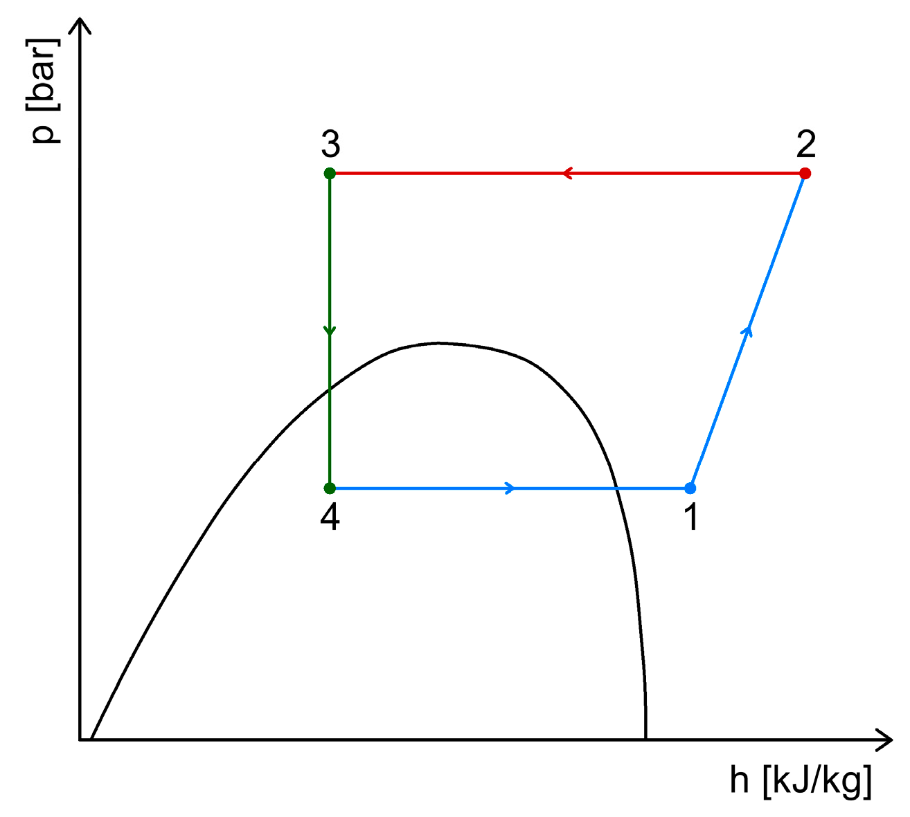
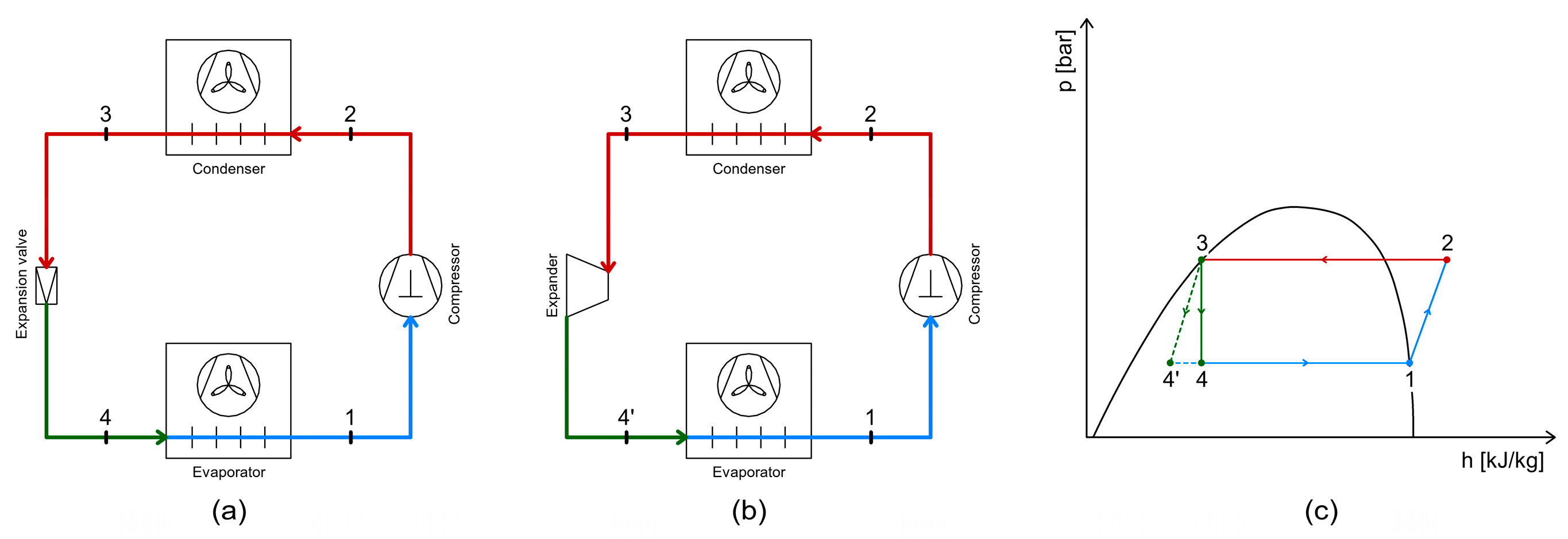
From the perspective of the operating cycle, in a transcritical CO2 refrigeration system, the heat rejection to the ambient environment takes place above the critical point, in the supercritical region. For this reason, the main difference between a conventional subcritical refrigeration system and a transcritical CO2 system is the replacement of the condenser with a gas cooler, in which the refrigerant is cooled at constant pressure (Figure 1 and Figure 2).
The other components remain the same: a compressor, which performs the compression process; an expansion valve, which reduces the pressure and enables the cooling effect; an evaporator, where heat is absorbed from the cooled space through the evaporation of the refrigerant.
The operating pressures in transcritical CO2 systems are significantly higher than those in conventional subcritical systems. Specifically, the discharge pressure of the compressors ranges from 70 to 130 bars, while the evaporation pressure varies between 15 and 35 bar, depending on the desired evaporation temperature. The refrigerant temperature at the compressor discharge can reach up to 140 °C.

2.2. Cascade Refrigeration System Using CO2 and Ammonia

In applications that require low temperatures, such as rapid freezing and frozen food storage, the evaporation temperature of the refrigeration system typically ranges between −40 °C and −55 °C. Under such conditions, a single-stage refrigeration system is insufficient.
For these types of applications, two-stage or cascade refrigeration systems are commonly used. The key difference between these two systems is that, in a two-stage system, both the high- and low-pressure sides use the same refrigerant, whereas in a cascade system, the high-temperature and low-temperature circuits use different refrigerants [9].
Therefore, the use of natural refrigerants in both two-stage and cascade systems contributes to meeting environmental protection requirements [10].
Cascade refrigeration systems are used in industrial applications, as well as in supermarket refrigeration systems, where the required evaporation temperature ranges from −30 °C to −50 °C [11]. In such systems, two single-stage circuits are connected via a heat exchanger, which acts as a condenser for the low-temperature circuit and an evaporator for the high-temperature circuit.
For the high-temperature stage, refrigerants such as ammonia (R717), propane (R290), propylene (R1270), ethanol, or R404A are typically used. For the low-temperature stage, carbon dioxide (R744) is commonly used [12].
Most often, ammonia and CO2 are used in cascade refrigeration systems. As a natural refrigerant, ammonia is widely used in industrial and commercial applications due to its favorable thermophysical properties and minimal environmental impact. However, its flammability and toxicity must also be taken into account [13].
One of the advantages of a R717–R744 cascade system is that it requires a significantly lower ammonia charge compared to systems that use only ammonia. Additionally, the COP (Coefficient of Performance) of the cascade system is comparable to that of a two-stage system operating at low temperatures [14].
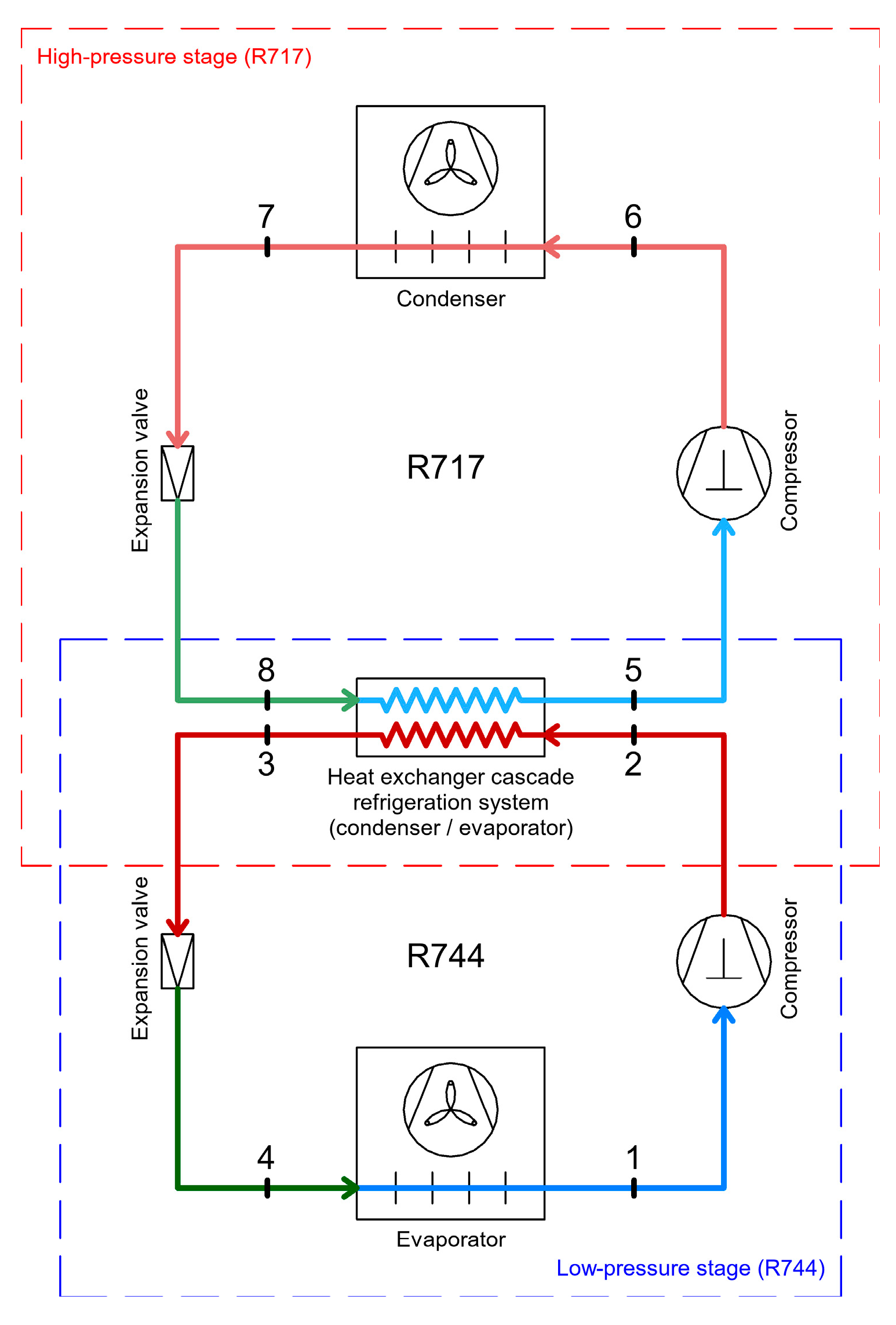
The schematic diagram of the R717–R744 cascade refrigeration system (Figure 3) consists, in both the high and low-pressure stages, of a compressor, condenser, expansion valve, and evaporator. Since this is a cascade system, the evaporator of the high-pressure stage serves as the condenser for the low-pressure stage.
In the high-pressure stage, ammonia (R717) is compressed to the condensation pressure (process 1–2), where it enters the condenser and rejects heat to the ambient environment (process 2–3). It then undergoes expansion in the expansion valve (process 3–4) down to the evaporation pressure of the high-temperature stage. After expansion, the ammonia enters the heat exchanger that connects the low- and high-pressure stages. In the heat exchanger, ammonia absorbs the heat released by the low-pressure stage (process 4–1).
In the low-pressure stage, carbon dioxide (R744) is compressed to the condensation pressure (process 5–6), where it rejects heat to the ammonia in the high-pressure stage (process 6–7). It then expands to the evaporation pressure of the low-temperature stage (process 7–8). In the evaporator, heat is absorbed from the cooled space by vaporizing the refrigerant (process 8–5).
The thermodynamic processes within the R717–R744 cascade refrigeration system can be seen in Figure 4.
The CO2/NH3 cascade refrigeration system with subcooling has a coefficient of performance (COP) that is 26% higher than that of the conventional HFC-404A system under design conditions, while the introduction of subcooling improves the COP of the conventional CO2/NH3 system by approximately 5%. The annual energy demand and total equivalent warming impact (TEWI) of the proposed system are 15% and 48% lower, respectively, than those of the conventional HFC-404A system, resulting in significant economic and environmental benefits [15].
Regarding the study of CO2–NH3 cascade refrigeration systems (CRS) with multiple evaporators used in seafood processing, the results show that the CRS with a single evaporator provides the greatest advantage in terms of the coefficient of performance (COP), of approximately 11.5%, in the surimi (fish protein) process, where the main cooling load is at the high-temperature evaporator. In contrast, the CRS with three evaporators has proven to be the most advantageous for the fish filet and shrimp industries, where the major cooling load is at the low-temperature evaporator. The observed advantages of COP are 16.5% for fish filets and 20.3% for shrimp/large shrimp [16].

2.3. Single-Stage CO2 Refrigeration System

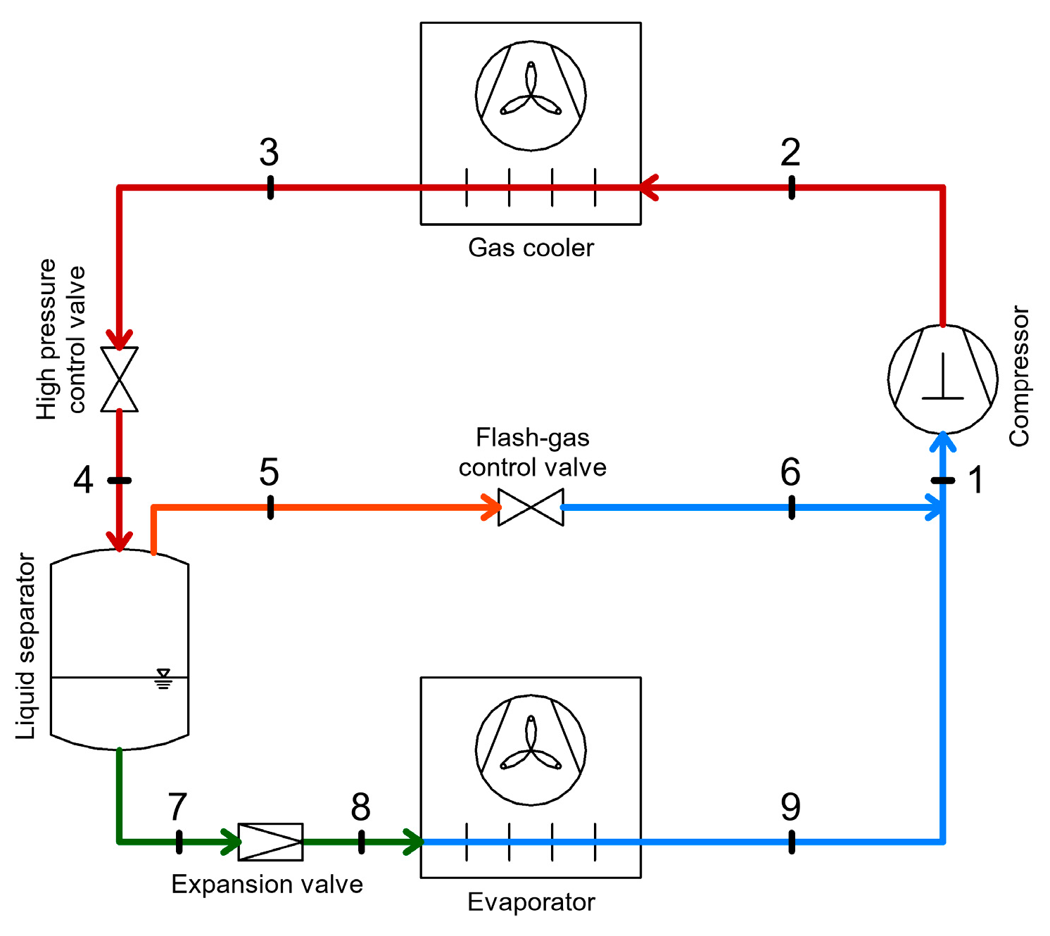
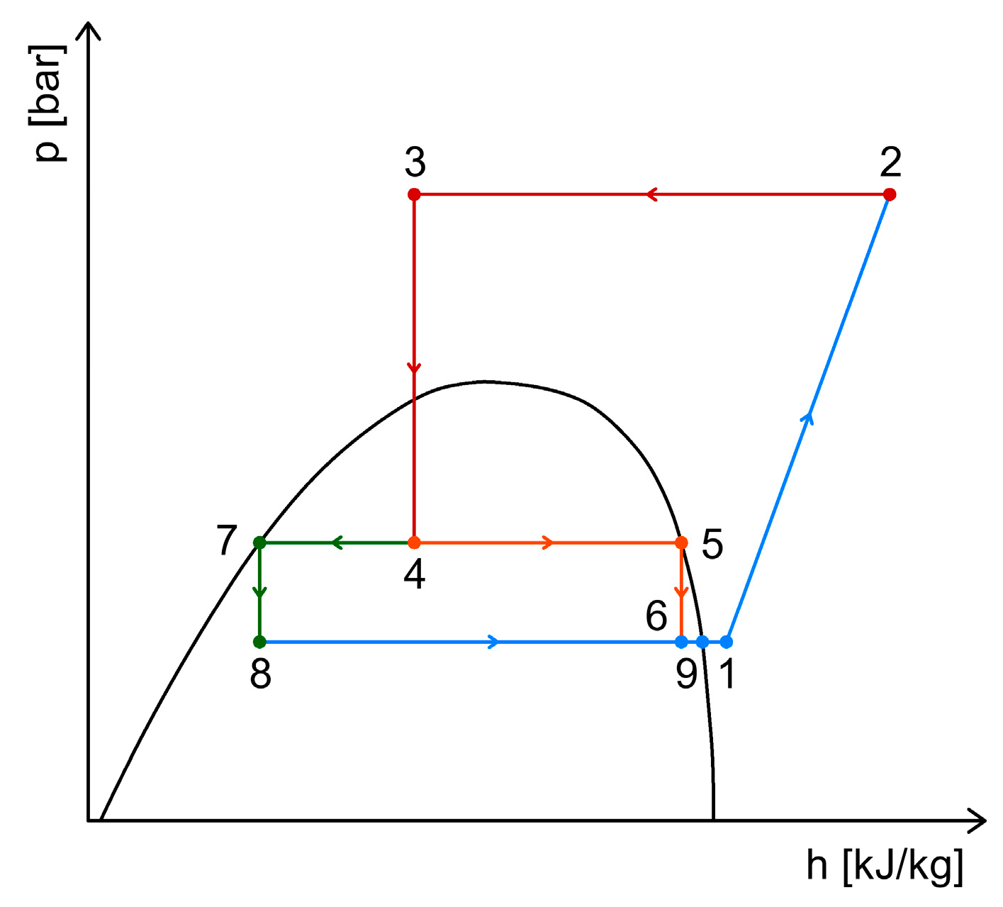
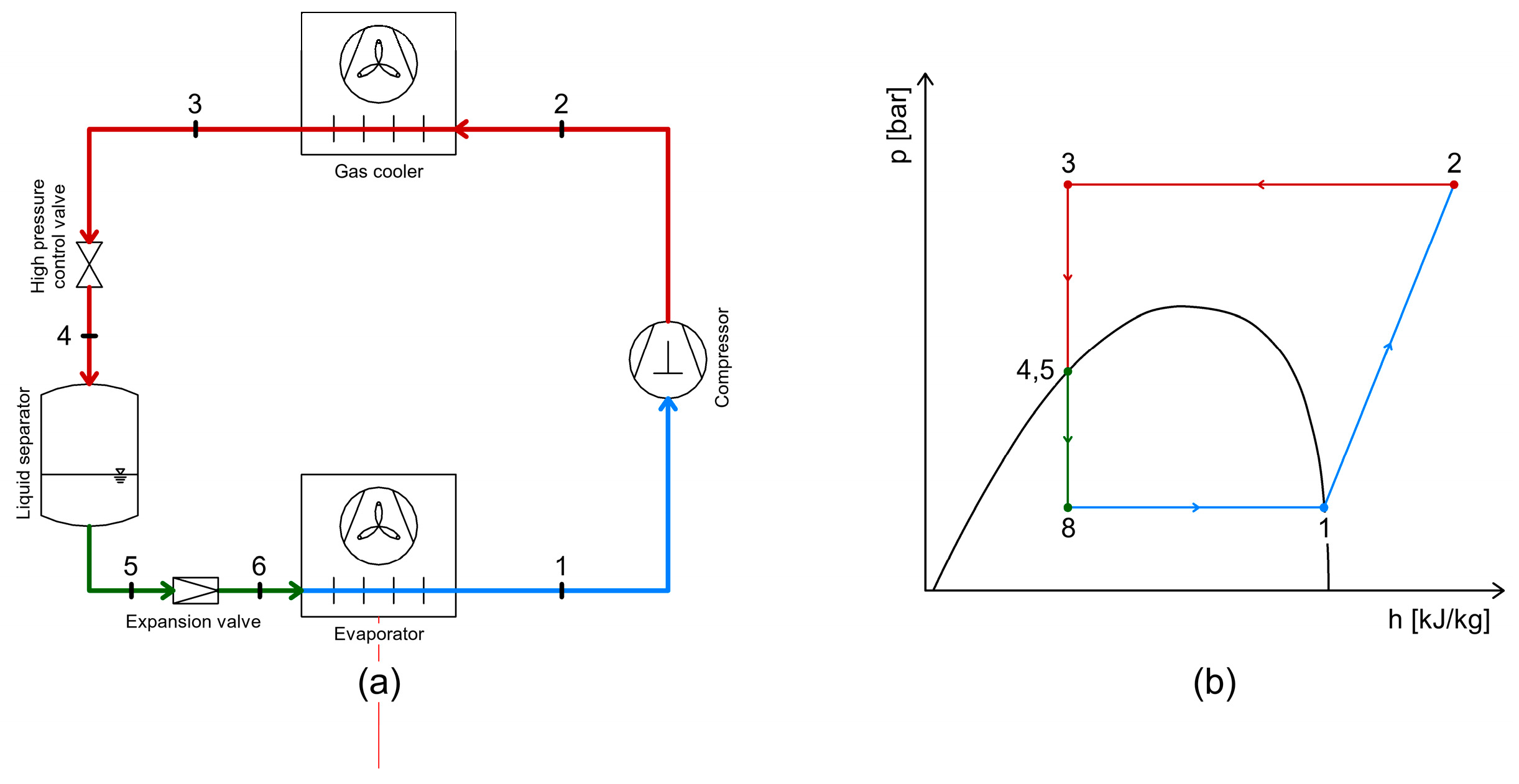
In the single-stage CO2 refrigeration system (Figure 5 and Figure 6), the pressure in the gas cooler is controlled by a pressure regulator that ensures the optimal pressure value to achieve the desired cooling capacity or maximum energy efficiency, while always maintaining the pressure below the maximum allowable limit. This control valve is regulated by two parameters: the pressure in the gas cooler and the temperature at the gas cooler outlet [17].
After releasing heat to the ambient environment through the gas cooler, the refrigerant enters the intermediate reservoir (liquid separator). Here, the separation between the liquid phase and vapor phase refrigerant takes place. The liquid refrigerant exits from the lower part of the separator toward the expansion valve and evaporator, while the vapor refrigerant exits from the upper part of the reservoir to the compressor suction. The pressure in the intermediate reservoir is controlled by a pressure regulator (control valve or vapor valve).
The coefficient of performance (COP) for this type of system varies widely. Unlike subcritical systems, the maximum COP does not occur at the minimum gas cooler pressure; instead, the optimal COP depends on the evaporation conditions and the temperature at the gas cooler outlet. Typically, the optimal COP is achieved at pressures between 90 and 100 bar [13].
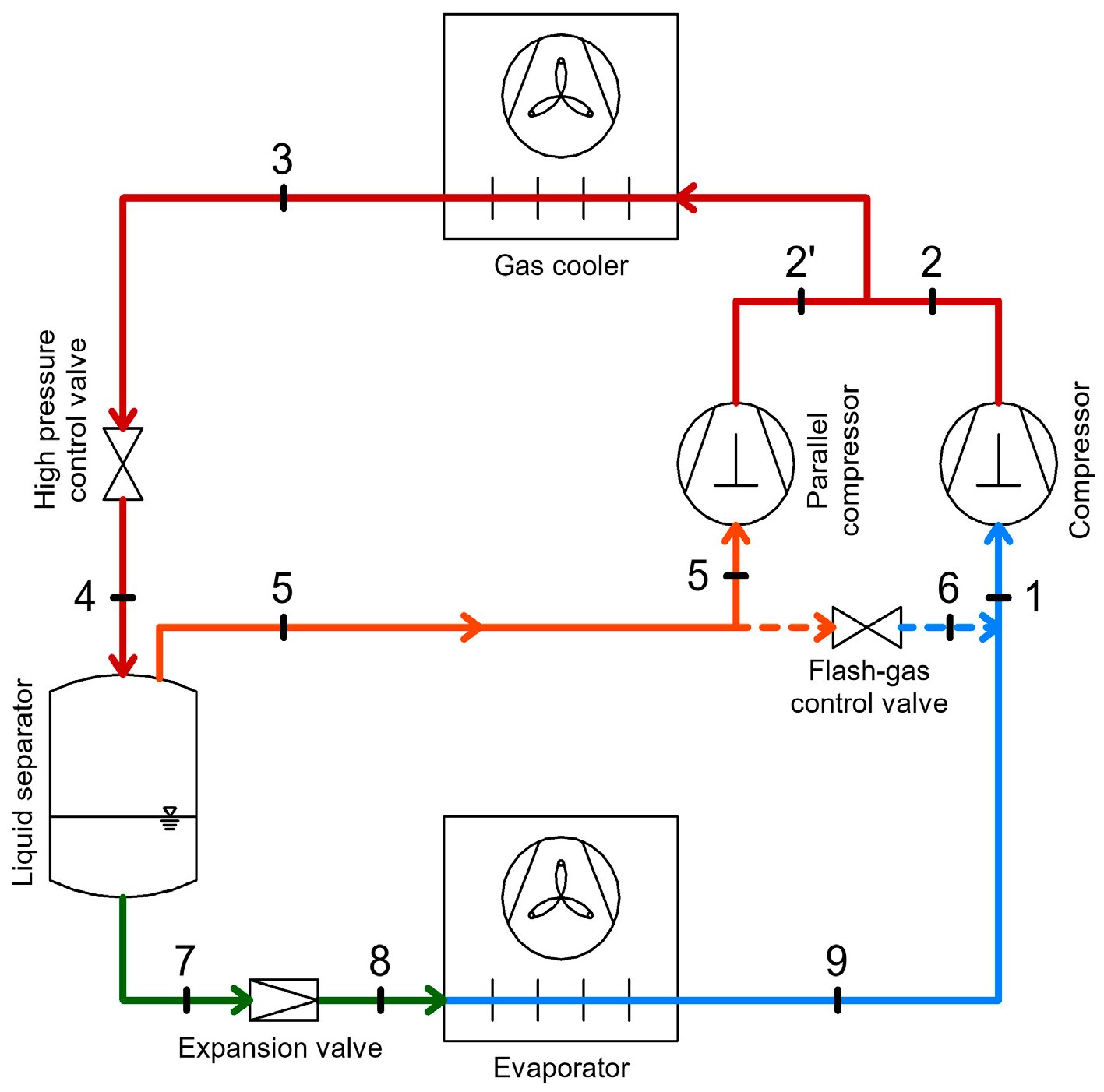
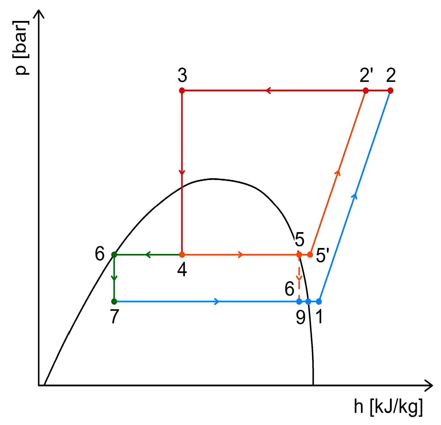
This system can be optimized by using an additional compressor that takes the vapor from the intermediate reservoir and compresses it up to the gas cooler pressure, achieving higher efficiency due to the higher suction pressure compared to the main compressor (Figure 7 and Figure 8). Thus, by employing parallel compression, a higher overall efficiency of the entire system is obtained [18].
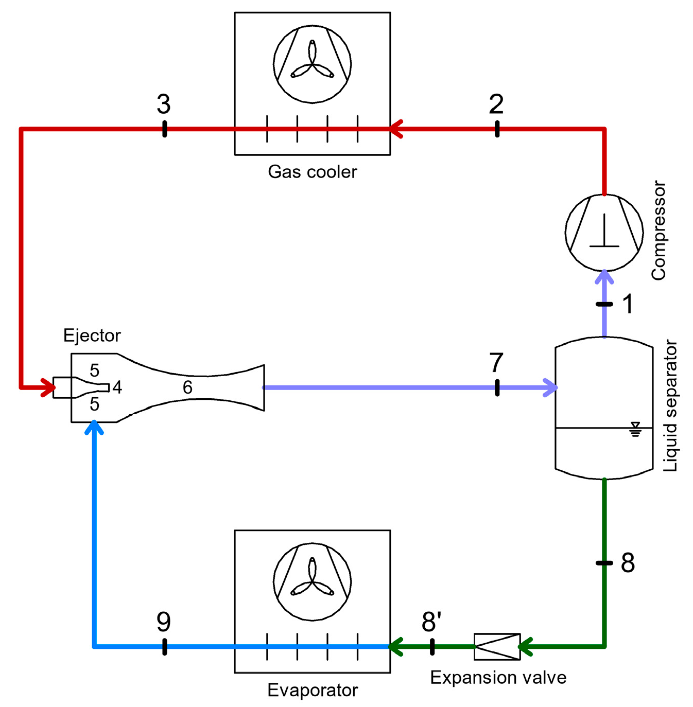
Another optimization method is the introduction of the ejector (Figure 9). The ejector utilizes the expansion power from the gas cooling pressure to raise the gas flow to a higher pressure (Figure 10 and Figure 11). Thus, the ejector increases the suction pressure of the compressor, which leads to lower compressor energy consumption and higher efficiency [1,19].
Another study, proposed a modified parallel compression transcritical CO2 cycle incorporating an ejector and subcooler to enhance performance. Results showed COP and cooling capacity improvements of 15.8% and 17.1%, respectively, with reduced compressor displacement and flash pressure. Exergy analysis identified the gas cooler and compressors as the main sources of system irreversibility [20].
As a result of the analysis of a transcritical compression system based on CO2, improved by integrating a two-phase ejector and an additional heat exchanger, a 12% increase in the coefficient of performance (COP), a 16% improvement in exergetic efficiency, and a 10% reduction in electrical energy consumption were observed [21].
An analysis of a modified transcritical CO2 refrigeration cycle integrated with an ejector and a subcooler proposed an ejector-enhanced transcritical two-stage CO2 refrigeration cycle for supermarket applications. The results showed that the modified system improved the coefficient of performance (COP) by 9.6–11%, increased the cooling capacity by up to 18.4%, and reduced carbon emissions by 17.9% compared to R404A systems, demonstrating both higher efficiency and environmental benefits [22].
Another study analyzed a CO2 multi-ejector refrigeration system with three controllable ejectors designed to enhance off-design performance. The results showed that the proposed optimum pressure control (OPC) strategy improved the cooling COP by up to 30.7% compared to a conventional single-stage system, achieving a maximum pressure lift of 656 kPa and demonstrating significant efficiency gains under varying operating conditions [23].

2.4. CO2 Booster Refrigeration System

This type of refrigeration system is primarily used in commercial applications such as supermarkets because it allows for two levels of cooling: refrigeration and freezing.
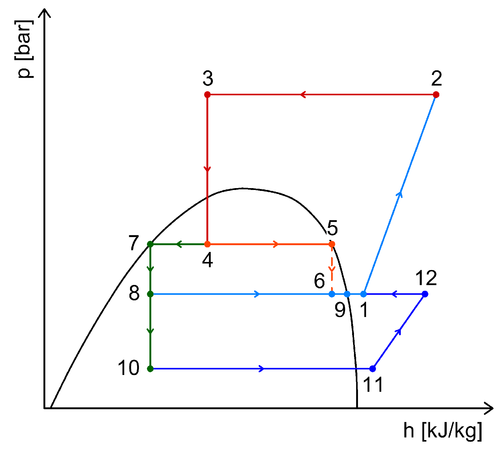
The CO2 Booster refrigeration system (Figure 12) is divided into four pressure stages: high pressure (gas cooler area), intermediate pressure (intermediate vessel area), medium pressure (medium temperature evaporator, refrigeration), and low pressure (low temperature evaporator, freezing) [24].
Typically, for CO2 Booster systems, the evaporation temperature for refrigeration ranges between −6 °C and −10 °C, while for freezing it ranges between −35 °C and −30 °C [18].
The MT compressor compresses the superheated gas from the medium pressure level to the gas cooler pressure (high-pressure level), state 2. Here, the gas is cooled at constant pressure by releasing heat to the ambient environment, state 3. After cooling, the gas passes through the high-pressure regulating valve and enters the intermediate reservoir, state 4, where the separation between the liquid refrigerant and vapor refrigerant takes place. The vapor refrigerant, state 5, exits from the upper part of the reservoir toward the suction of the MT compressor, passing through the vapor regulating valve, state 6. The liquid CO2 exits from the lower part, state 7, toward the medium temperature evaporator and the low temperature evaporator, being throttled by expansion valves, states 8 and 10.
The refrigerant exiting the low temperature evaporator is suctioned by the LT compressor, state 11, compressed from the low-pressure level to the medium pressure level, state 12, then mixed with the refrigerant exiting the MT evaporator (state 9) and with the vapors resulting from the separation of the two-phase agent in the intermediate reservoir (state 6). This vapor mixture is suctioned by the MT compressors, state 1.
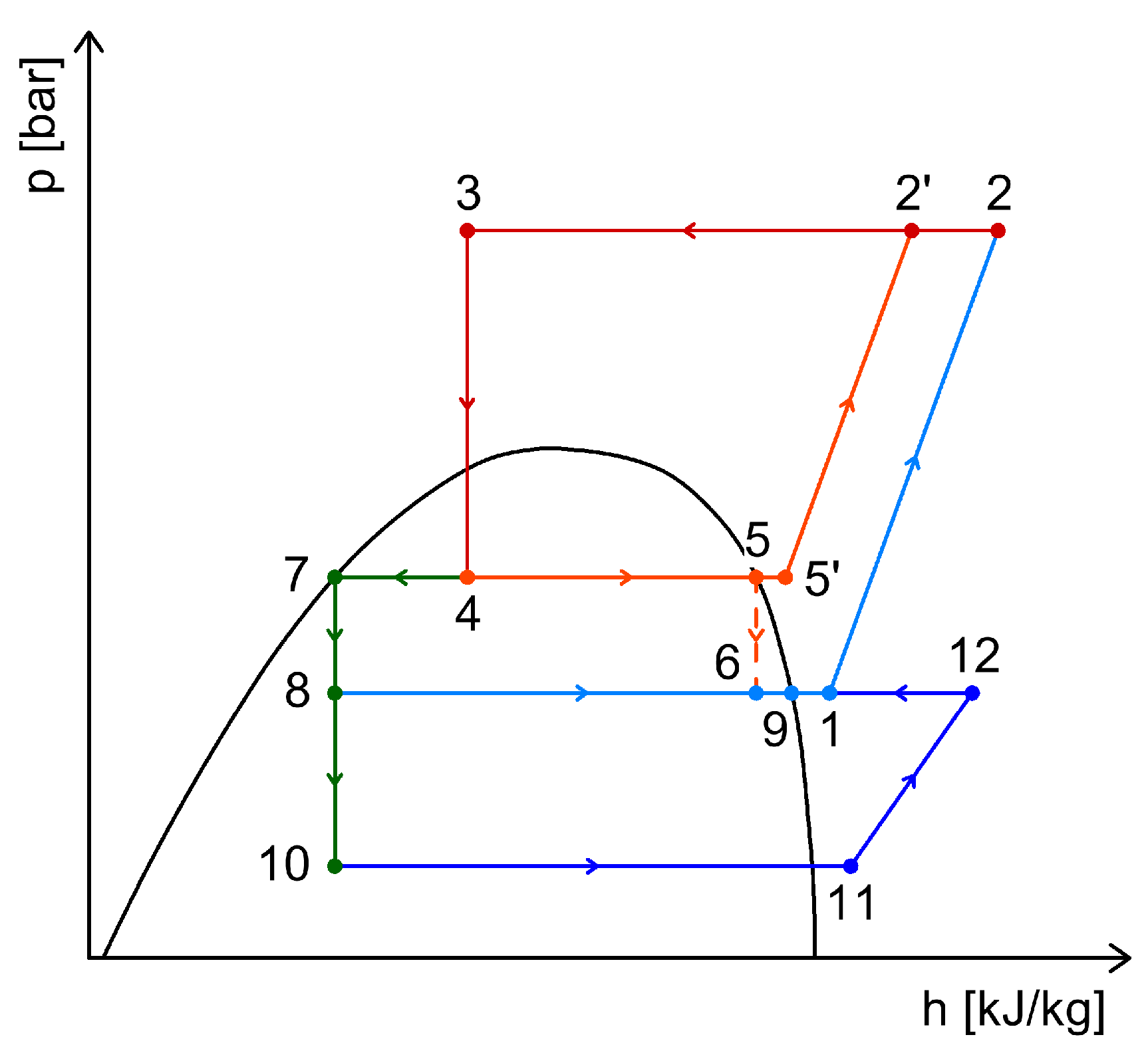
The thermodynamic processes within the CO2 Booster refrigeration system are shown in Figure 13.
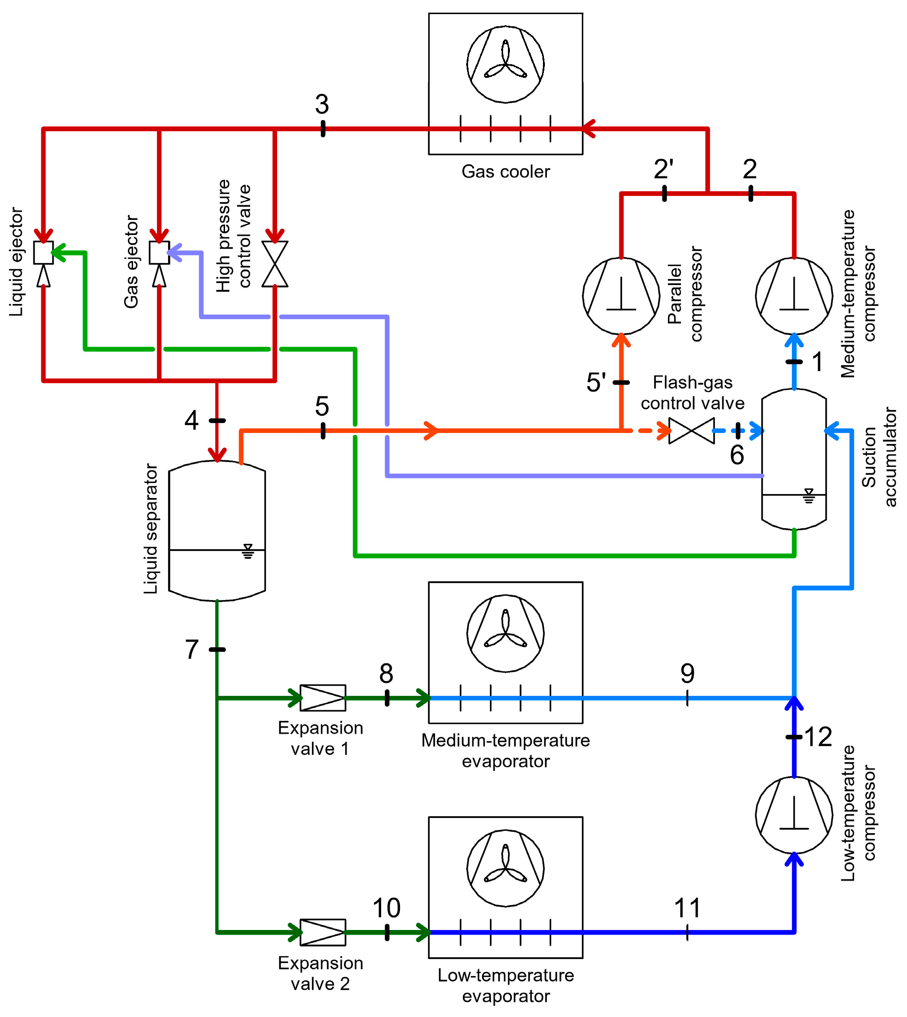
To optimize and increase efficiency, a compressor is used to take the vapor flow from the intermediate vessel and compress it up to the gas cooler pressure (Figure 14), achieving higher efficiency due to the higher suction pressure compared to the main MT compressor. Thus, by using parallel compression, the overall system efficiency is improved [1].
By compressing the gas from the intermediate vessel with the parallel compressor (process 5–2′, Figure 15), part of the energy consumed by the MT compressor is saved. The benefit of parallel compression is especially noticeable in warmer climates, where the temperature at the gas cooler outlet is higher. A higher refrigerant temperature at the gas cooler outlet leads to a larger refrigerant flow rate in the separator vessel [18].
Besides the use of parallel compression, an additional optimization is the use of an ejector or multiple liquid/vapor ejectors (Figure 16).
Thus, ejectors are installed in parallel with the high-pressure valve. These ejectors partially recover pressure losses from the high pressure to the intermediate pressure by transporting gaseous or liquid CO2 from the suction accumulator tank of the MT compressors back to the intermediate tank. This process increases the system’s efficiency by allowing the evaporators to operate without superheating, thereby improving heat transfer at the evaporators and enabling a significant increase in the evaporation temperature.
A new study developed a steady-state theoretical model for CO2 booster refrigeration systems in supermarkets, validated with field data from three UK stores. The model introduced improved methods to infer missing variables, enhancing accuracy and thermodynamic consistency. The results showed strong agreement with real measurements, confirming the model’s reliability for evaluating system performance under various operating conditions [25].
A Chilean perspective compared booster (BB) and parallel compression (BP) CO2 refrigeration systems for supermarkets using detailed energetic modeling. Results showed that the BP configuration achieved a 14% higher COP and reduced annual energy use by 4–12%, depending on climate. However, economic analysis indicated that BP is only cost-effective in warm and desert regions, while BB remains more profitable in colder areas [26].
The authors of another paper examined a transcritical CO2 vapor ejector-based refrigeration system for marine applications, comparing it with a conventional R407F system. Results showed a maximum COP improvement of 13.2% at 26 °C seawater temperature and identified major exergy losses in the gas cooler, ejector, and valve. The avoidable exergy destruction reached 33.6%, indicating strong potential for further system optimization [27].
Another study developed a dynamic model of a transcritical CO2 refrigeration system with a multi-ejector, validated against experimental data. The model analyzed system responses to various operating disturbances and proposed a control strategy based on nozzle mass flow rate (0.066–0.070 kg·s−1) to maintain high performance. Results showed that the optimal ejector combination maximizes system efficiency and pressure lift, improving regulation of cooling and heating loads under varying conditions [28].
For the CO2 refrigeration system configurations presented above, Table 1 provides a concise and intuitive overview of the available methods for heat and energy recovery. The heat and energy recovery strategies summarized in this table are further described and discussed in Section 3 and Section 4.

3. Heat Recovery Possibilities Within CO2 Refrigeration Systems

Cooling processes generate considerable amounts of heat. When this heat is not utilized, it is considered waste heat. The use of waste heat is beneficial in situations where heating and cooling are needed simultaneously, or where waste heat can be stored, such as:
  • In air conditioning systems for reheating dehumidified air;
  • In butcheries, dairy factories, hotels, etc., where on one hand refrigerated rooms are operated, and on the other hand, there is always a high demand for domestic hot water;
  • In stores, where besides cooling food products, there is also a demand for heat;
  • In cold storage areas, for heating and domestic hot water;
  • In industrial processes (e.g., drying processes) [29].
Due to the high operating pressures (which generate high temperatures) of the CO2 refrigerant, it is the perfect refrigerant for considering heat recovery possibilities in installations where it is used.
It has been found that transcritical CO2 refrigeration systems can meet the entire cooling demand, as well as a significant part of the heating demand of the buildings where they are installed (supermarkets, factories, cold storage warehouses). The integration of cooling and heating in these systems leads to a lower annual energy consumption compared to a conventional R404A refrigeration system with a separate heat pump for heating [30]. Transcritical CO2 systems can be controlled to simultaneously provide the necessary cooling and heating capacity, but proper control is required to operate with the highest possible efficiency [31].

3.1. Heat Recovery from the High-Pressure Compressor Discharge

Typically, at the compressor discharge, CO2 reaches temperatures between 80 °C and 120 °C, which from the heat recovery perspective offers a high-temperature heat source. Additionally, in transcritical refrigeration systems, the area where CO2 cools in the gas cooler presents the highest heat capacity that can be recovered—heat that is normally discharged into the ambient environment.
Due to the high discharge temperature and high enthalpy compared to traditionally used synthetic refrigerants, a large portion of the heat released to the environment can be recovered with higher efficiency compared to other traditional refrigerants.
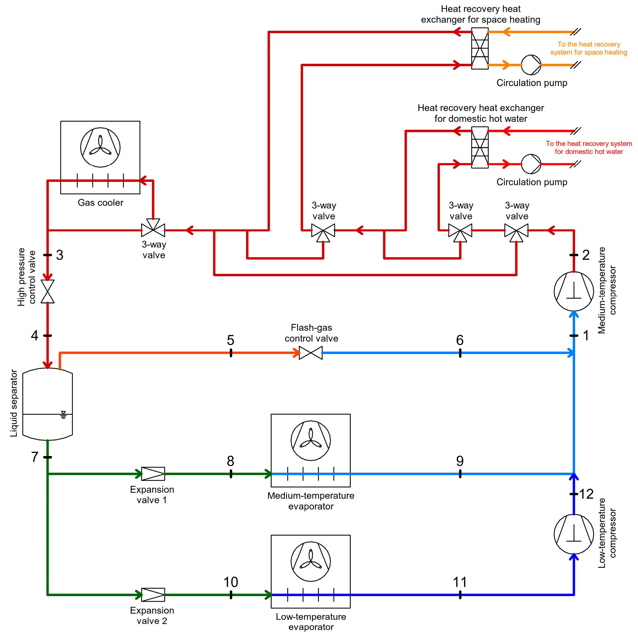
To enable heat recovery, one or two heat exchangers connected in series are used at the compressor outlet, before the gas cooler (Figure 17 and Figure 18). These heat exchangers are connected to intermediate circuits for heat storage and distribution, and used to recover heat at different temperature levels such as: domestic hot water (the temperature of the circuit between the heat exchanger for domestic hot water and the storage tank is 70–50 °C) and direct space heating (the temperature of the circuit between the heat exchanger for space heating and the storage tank is 50–40 °C) [32].
In practice, the discharge temperature of high-pressure compressors in a transcritical CO2 system is usually above 55 °C, even under winter conditions. Therefore, heat recovery (for example, for domestic hot water) is possible without increasing the pressure, which enables heat recovery at the highest possible COP from a refrigeration perspective. The higher the ambient temperature, the more heat can be recovered without compromising the system’s COP [33].
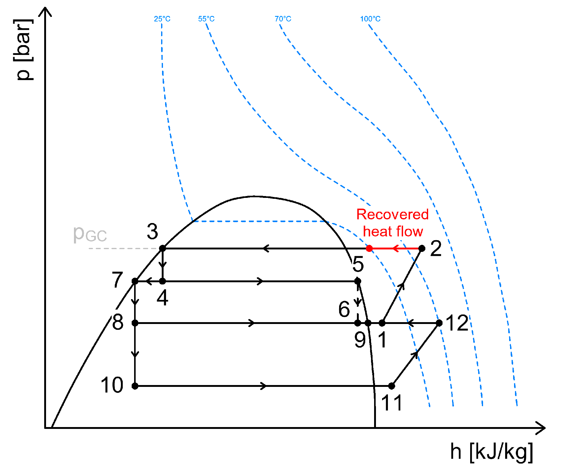
If the heat demand is higher (such as for space heating during winter), the system can resort to increasing the pressure in the gas cooler. This leads to a higher compressor work volume, but without a significant decrease in overall system performance (Figure 19). By adding only a limited amount of additional mechanical work to the compressor, it is possible to recover approximately 80% of the heat (from 100 °C down to 25 °C). Only about 20% of the heat cannot be recovered, since the gas temperature drops below 25 °C [33].
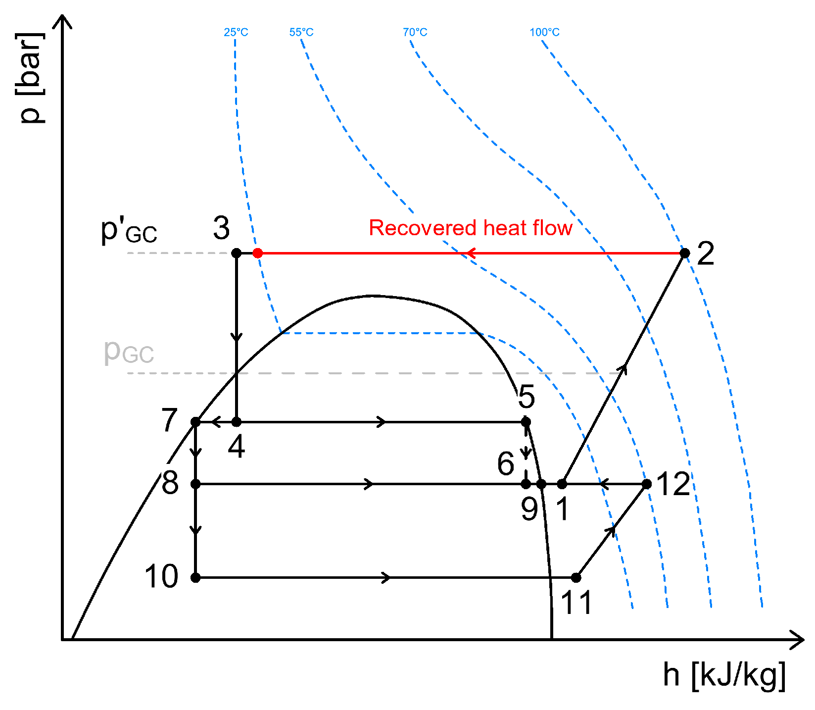
In order to recover the final portion of heat rejected to the ambient through the gas cooler, the gas cooler must be bypassed. However, this procedure leads to a decrease in cooling capacity. To maintain the same cooling capacity, the discharge pressure of the compressors must be increased (which also requires a higher mass flow rate of refrigerant or longer compressor operation time). This results in a decrease in the COP but allows for the possibility to recover 100% of the heat generated from 100 °C down to 25 °C (Figure 20).
When bypassing the gas cooler, the gas temperature increases from 5 °C (only at low ambient temperatures) to 25 °C, enabling the recovery of the entire heat generated by the refrigeration system (Figure 21).
It has been found that by recovering heat under normal operating conditions of the refrigeration system—meaning without increasing the system’s mass flow rate or the compressor discharge pressure—a reduction of up to 48% in natural gas consumption used in building heating systems can be achieved, along with a reduction in operating costs of up to 6.2%.
The most attractive method to meet the demand for recovered heat is by increasing the compressor discharge pressure. This method allows for a reduction of up to 32% in total energy consumption and eliminates the use of natural gas.
From a cost perspective, the most efficient method is to use natural gas only when its cost is lower than the cost of heat recovery in operation (i.e., when increasing the discharge pressure too much toward the allowable limit results in a significant increase in the compressors’ electricity consumption) [34].
Compared two-stage and one-stage heat recovery in CO2 supermarket refrigeration systems to identify optimal discharge pressures and improve heat recovery performance. Results showed that two-stage heat recovery increased the heating SPF by 17%, achieved up to 4% annual energy savings, and improved heat export efficiency by 25%, with only minor performance penalties at slightly higher discharge pressures [35].
Techno-economic analysis of heat recovery from supermarket’s CO2 refrigeration systems to district heating networks analyzed the potential of CO2 supermarket refrigeration systems to supply excess heat to district heating networks. Using the BIN method and sensitivity analysis, results showed that up to 16% annual energy cost savings and 18% CO2 emission reductions could be achieved, with higher profitability at lower network return temperatures [36].
A case study of four real-world installations analyzed four Swedish supermarket case studies from a techno-economic perspective. All studied supermarkets have CO2 booster systems with heat recovery and their technical efficiency are evaluated, as well as already accomplished economic savings. This study estimates that the studied supermarkets are currently saving the equivalent of 4–12% of the energy costs for refrigeration and heating. Also, higher annual economic savings of 14–42% could be achieved if the refrigeration systems were instead controlled to cover all the heating demands in the supermarkets, or savings of 24–58% if also selling a surplus to nearby consumers [37].
The heat available for recovery at the high-pressure compressor discharge can also be recovered using organic Rankine cycle (ORC) systems. In this way, the heat is converted into work and, through an electric generator, into electricity. This topic will be addressed by the authors in future work [38].

3.2. Heat Recovery Between the Gas Cooler and the Intermediate Separator Receiver

By integrating a heat exchanger before the separator receiver (Figure 22), it is possible to partially or fully cover the cooling demand of the building’s air conditioning system where the refrigeration system is installed [34].
The heat exchanger for air conditioning cooling is a plate heat exchanger, with the secondary fluid being water or glycol, typically cooled from 12 °C to 7 °C, but other temperature configurations can also be accommodated.
Using this heat exchanger, cooling capacities ranging from 50 to 250 kW can be provided for the air conditioning system [34].
Compared to a freon-based cooling system used for air conditioning, it has been found that the heat recovery function for air conditioning within the CO2 Booster system is more efficient at moderate ambient temperatures below 20–25 °C, while at temperatures above 25 °C, the efficiency is lower than that of conventional freon cooling systems [39].
Have been monitorized an integrated CO2 transcritical booster system serving a supermarket in Italy, capable of providing refrigeration, heating, and air-conditioning. Results showed performance limitations at high ambient temperatures but full heat recovery in winter. Simulations indicated that combining overfed evaporators, ejectors, and an evaporative gas cooler could increase the annual COP by up to 18%, improving system efficiency in warm climates [40].

3.3. Heat Recovery for Defrosting Evaporators

Refrigeration systems operating at evaporation temperatures below zero degrees Celsius face the problem of ice accumulation on the evaporator tubes and fins. This ice forms as a result of freezing water vapor from the air.
The produced ice acts as an insulator between the heat that must be transferred from the cooled space and the refrigerant, which leads to reduced evaporator efficiency. Therefore, certain techniques are necessary to periodically remove the ice deposited on the coils and evaporator fins.
There are several types of defrosting methods: Natural (using air as a defrosting agent); Using hot gases (taken from compressor discharge); Using hot water or glycol; Electrical (using electric resistors); Using other external heat sources.
Defrosting methods using hot gases or hot water/glycol can be considered heat recovery processes that improve the overall coefficient of performance of the refrigeration system. Moreover, using these methods instead of electrical defrosting significantly reduces energy consumption.

3.3.1. Heat Recovery Through Defrosting Evaporators with Hot Gases

The hot gas defrosting method operates on the following principle: a portion of the high-temperature vapor resulting from compression is directed through a separate path to the evaporators, where it heats the evaporator coil and thus removes the formed ice.
This defrosting process is primarily applied in industrial or commercial systems where there are two cooling temperature levels (refrigeration and freezing) and where the cooled spaces at low temperatures are very large. Consequently, the evaporators installed in these spaces have higher cooling capacities and larger cooling coils than typical evaporators. If electrical resistance defrosting were used, the electricity consumption for these types of evaporators would be significantly higher, and the energy efficiency would decrease considerably.
Using the hot gas defrosting method has been found to reduce defrosting time compared to other methods, because the heating capacity required for defrosting increases. Hot gas defrosting increases the system’s COP by up to 8.5% [41].
The time required for a complete hot gas defrost cycle is approximately 15 min, but this period is closely related to the flow rate of hot gases passing through the evaporator [42].
Since there are two compression stages, hot gases can be taken from the low-pressure compressors because, in that zone, the gas temperature is optimal for defrosting purposes.
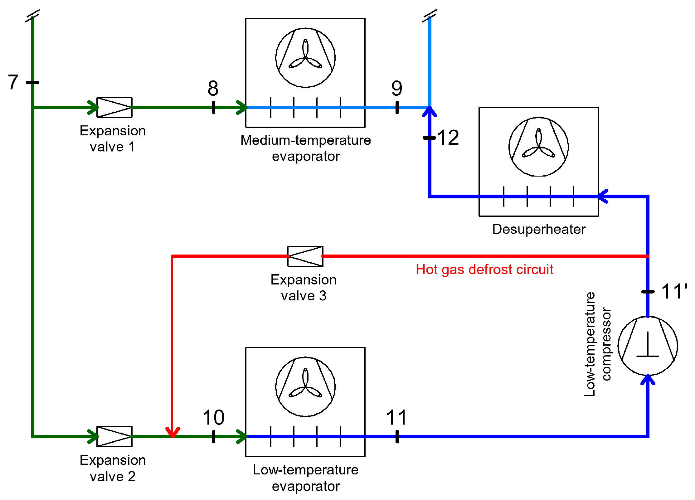
In CO2 Booster systems, after the low-temperature compressors, an intercooler is used to cool the discharge gas from the low-pressure compressors (heat is released to the ambient air, air cooling) to reduce the refrigerant temperature and improve system performance (Figure 23).
Between the low-pressure compressor and the intercooler, a hot gas line is installed that directs the hot gases towards the evaporators for the defrosting process. There are two types of hot gas defrosting methods based on the construction of the evaporators: either the same coil used for the evaporation of the refrigerant also carries the hot gas (Figure 24), or the evaporator contains a separate coil through which the hot gas circulates (Figure 25).
Since part of the hot gases taken from the discharge of the low-pressure compressors is used for the defrosting process instead of being cooled in the intercooler, the hot gas defrosting process can be considered a heat recovery process.

3.3.2. Heat Recovery Through Defrosting of Evaporators with Hot Glycol

The defrosting method using hot glycol involves an independent glycol circuit between the hot water storage tank within the heat recovery system for space heating and the evaporators that require defrosting (Figure 26). Using a coil integrated in the hot water storage tank, the glycol is heated and then transported by a circulation pump to evaporators equipped with an independent coil that heats the cooling coil inside the evaporators. Typically, a 45% concentration of propylene glycol is used for the defrost circuit.
The glycol temperature for defrosting is generally around 25 °C, and when returning to the hot water storage tank, it is approximately 15–18 °C. The time required for the defrosting process is about 20–25 min.

3.4. Heat Recovery Through Internal Heat Exchangers in Refrigeration Systems

Internal heat exchangers in refrigeration systems are used to superheat or subcool the refrigerant at certain points within the system. These processes are essential for optimizing and improving the performance of refrigeration systems; however, it is necessary to impose limits on the degree of superheating or subcooling, as exceeding these limits can negatively affect the system’s coefficient of performance.

3.4.1. Heat Recovery Through Internal Heat Exchangers Acting as Superheaters

The internal heat exchanger used to superheat the refrigerant at the compressor suction (Figure 27) serves to ensure the proper operation of the refrigeration system by preventing the compressor from suctioning liquid refrigerant. The presence of liquid refrigerant at the compressor suction can cause severe damage to the compressor [43].
By using the internal heat exchanger functioning as a superheater (Figure 28), two opposing effects occur within the refrigeration system, which can lead to either an increase or a decrease in system efficiency [44,45]. The positive effect is that the internal heat exchanger increases the specific cooling capacity of the cycle and eliminates the risk of liquid suction into the compressors. However, the negative effect is that the refrigerant at low pressure is superheated, leading to an increase in the compressor suction temperature, which reduces the refrigerant mass flow rate, increases the mechanical work required for compression, and raises the compressor discharge temperature [46].
Nevertheless, it has been found that the introduction of an internal heat exchanger functioning as a superheater provides a major positive effect compared to the negative impacts it may cause in the operation of refrigeration systems, especially when the ambient temperature is high. Thus, by integrating this superheater heat exchanger, at ambient temperatures between 35 and 43 °C, the system’s COP can increase by 23 to 35% [47].
For single-stage CO2 refrigeration systems to achieve maximum performance, several configurations have been developed featuring different placements of the superheater heat exchanger [48].
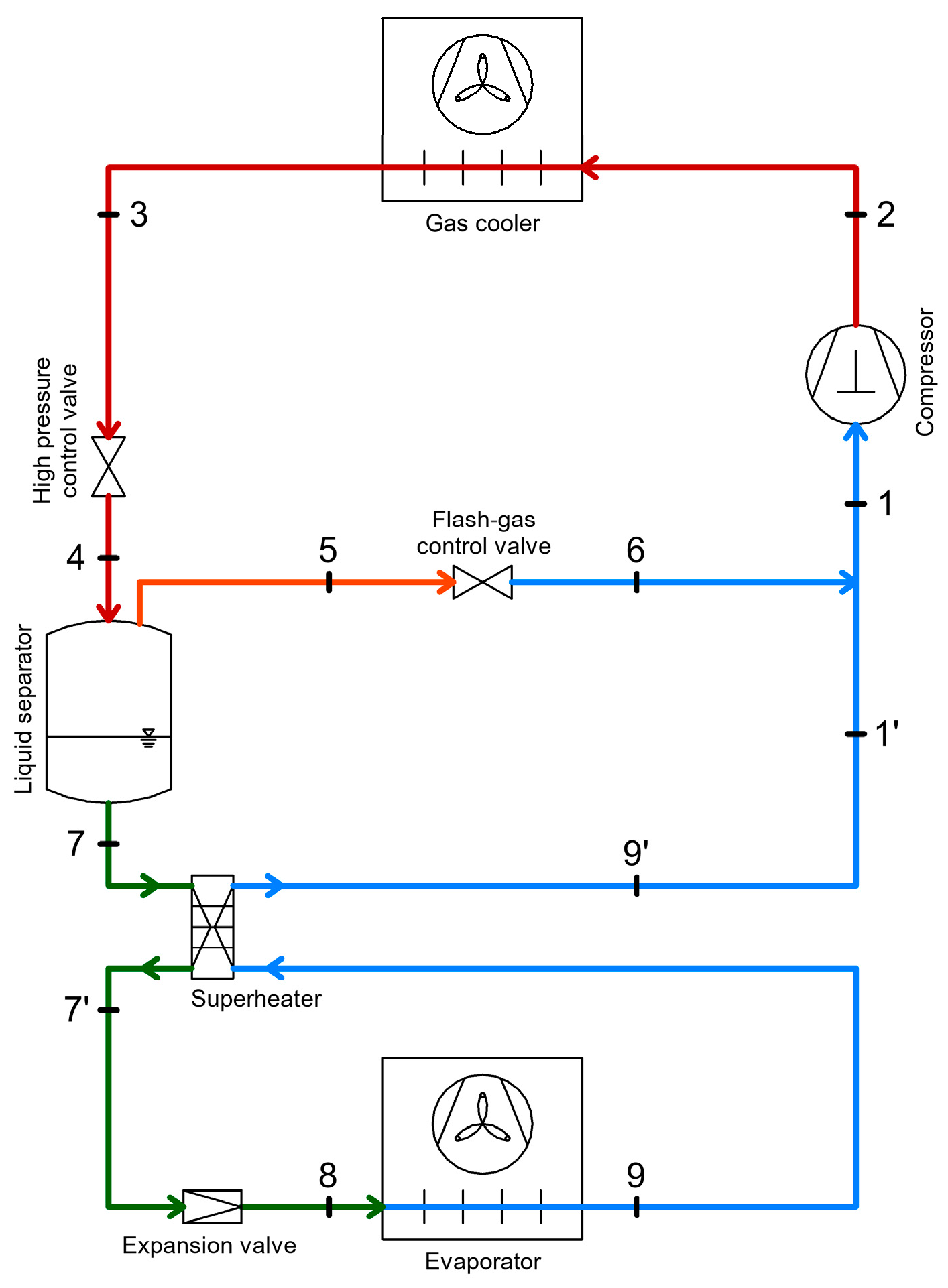
One initial variant integrates the heat exchanger at the outlet of the gas cooler, before the high-pressure expansion valve (Figure 29).
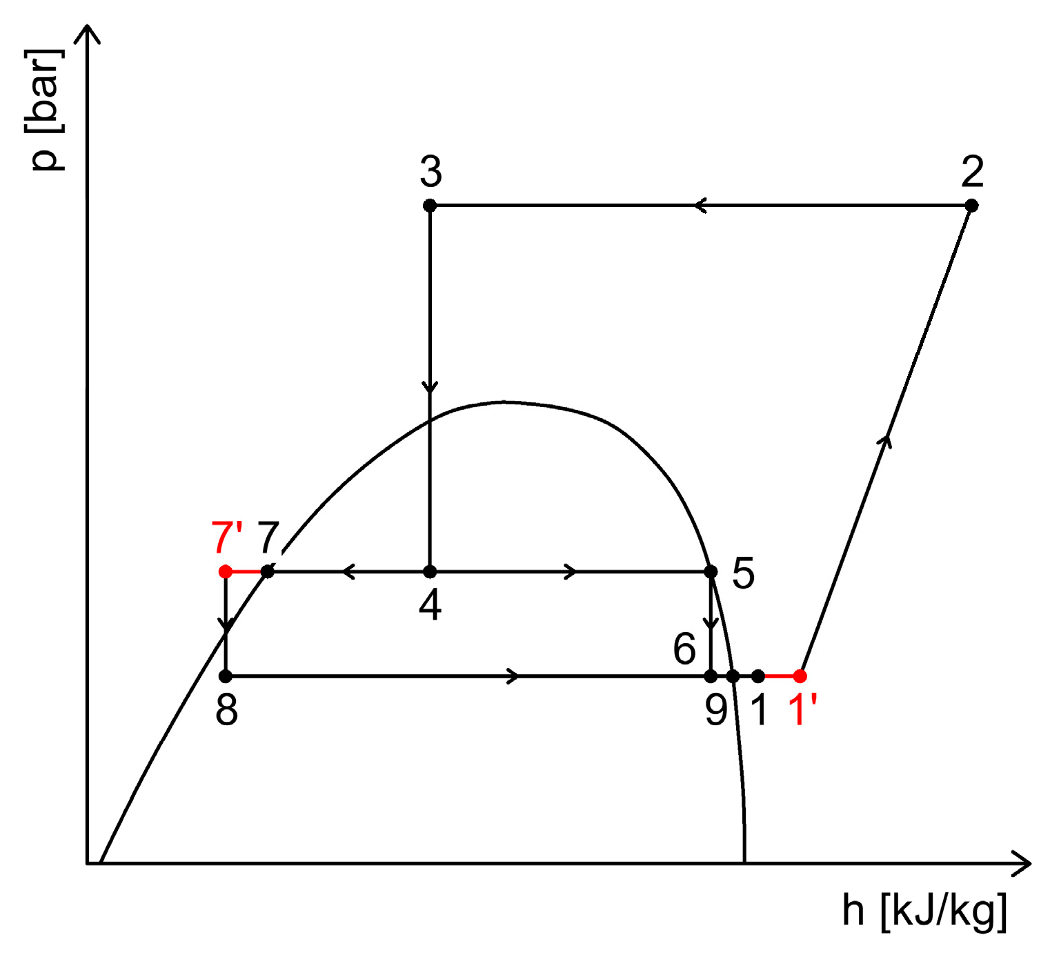
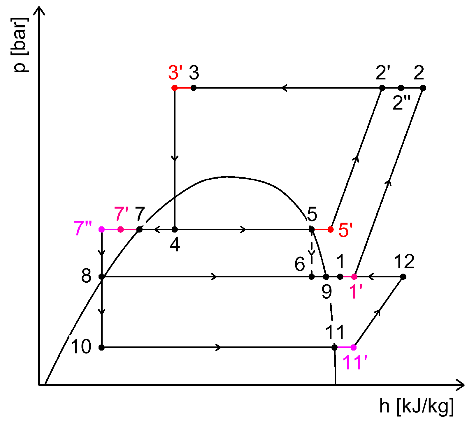
In the operating cycle on the p–h diagram (Figure 30), the thermodynamic superheating process at the vaporizer outlet (1–1′) and the heat source used for superheating (3–3′) can be observed.
By integrating the superheater at the outlet of the gas cooler, an increase in the system’s coefficient of performance (COP) is always achieved, regardless of operating conditions, with a maximum COP increase of 10.6% [48]. Another option for integrating a superheater is to place it after the separator vessel, on the liquid side, towards the evaporator (Figure 31).
In the operating cycle on the p–h diagram (Figure 32), the thermodynamic process of superheating at the outlet of the evaporator (1–1′) and the heat source used for superheating (6–6′) can be observed.
Integrating the superheater at the outlet of the separator vessel is not always beneficial for the system because the mechanical work in the compression process increases and the compressor discharge temperature rises. Even under these conditions, a maximum increase of 6.17% in the coefficient of performance (COP) of the system was achieved [48].
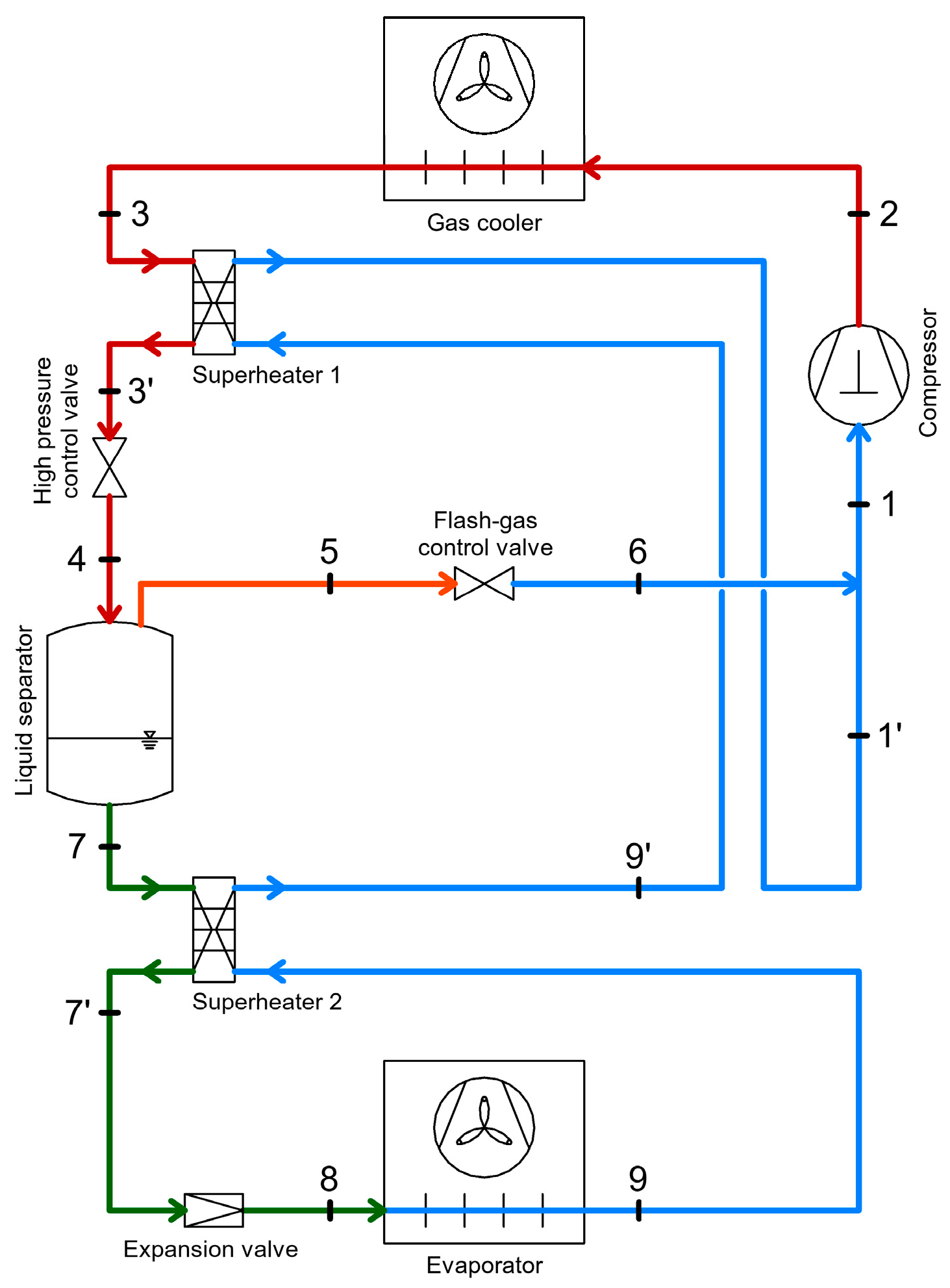
Ultimately, it was found that the two previously presented superheater placement options (Figure 29 and Figure 31) can be combined, yielding favorable results through staged superheating.
Thus, by integrating both a superheater at the outlet of the gas cooler (Superheater 1) and one at the outlet of the separator vessel (Superheater 2) within the same system (Figure 33), an increase in COP of up to 13% can be achieved [48].
In the operating cycle on the p–h diagram (Figure 34), the thermodynamic process of superheating at the outlet of the evaporator (1–1′) and the heat sources used for superheating (3–3′ and 6–6′) are observed, along with the fact that superheating the refrigerant at the evaporator outlet also leads to an increase in the specific cooling capacity (segment 7–1).
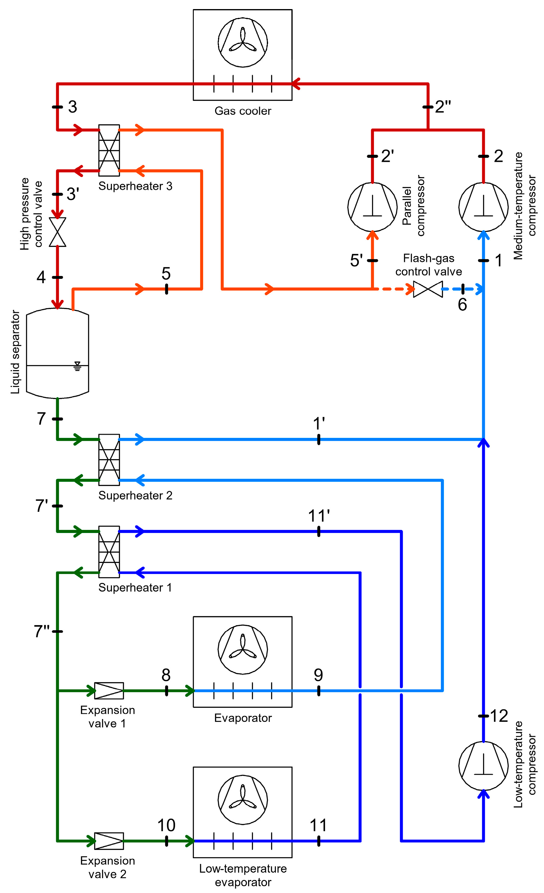
In commercial CO2 Booster refrigeration systems, multiple superheating processes are necessary to increase the system’s efficiency. Due to the complex configuration and the large number of compressors serving multiple pressure stages, internal heat exchangers have been integrated to superheat or subcool refrigerant. Figure 35 shows the three internal heat exchangers that superheat the refrigerant at the compressor suction in a CO2 Booster refrigeration system with parallel compression.
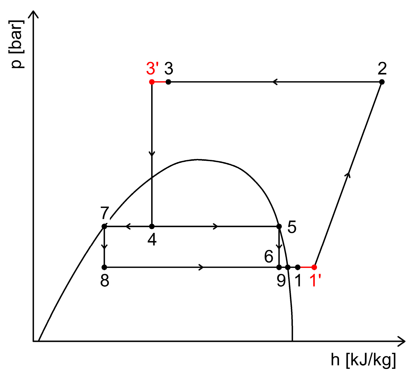
For superheating the refrigerant before the suction of the low-pressure stage compressor (LT Compressor), a heat exchanger (Superheater 1) is used, connected after the separator vessel on the liquid line. As shown in Figure 36, the refrigerant is superheated before entering the LT compressor (process 11–11′), while the refrigerant in liquid state before expansion is subcooled (process 7′–7″). The superheating degree at compressor suction is considered a minimum of 10 K, and the subcooling degree on the liquid side is at least 4 K.
For superheating the refrigerant before the suction of the medium-pressure stage compressor (MT Compressor), another heat exchanger (Superheater 2) is used, connected after the separator vessel on the liquid line, before Superheater 1. Thus, the refrigerant is superheated before entering the MT compressor (process 1–1′), and the liquid refrigerant before expansion is subcooled (process 7–7′). The minimum superheating degree for compressor suction is 10 K, and the minimum subcooling on the liquid side is 4 K.
When the CO2 Booster refrigeration system is also equipped with parallel compression, the refrigerant aspirated by the parallel compressor must be superheated. For this purpose, a heat exchanger (Superheater 3) is used, connected to the outlet of the gas cooler, before the high-pressure expansion valve. The refrigerant is superheated before entering the parallel compressor (process 5–5′), and the refrigerant leaving the gas cooler is subcooled (process 3–3′).

3.4.2. Heat Recovery via Internal Heat Exchangers with Subcooling Function

By employing the subcooling process, the refrigerant undergoes additional cooling after exiting the gas cooler and before entering the separator tank. This subcooling enhances the performance of the system, particularly under transcritical operation conditions [49].
Several CO2 refrigeration systems subcooling methods have been identified, many relying on external cooling sources:
  • Dedicated mechanical subcooling: This involves integrating an additional vapor compression refrigeration system using a different refrigerant. The evaporator of this auxiliary system is connected to the outlet of the gas cooler to achieve optimal subcooling. Using such a setup boost both the cooling capacity and performance of the main CO2 system [50];
  • Thermoelectric subcooling: Based on the Peltier effect, this method creates a temperature difference between two semiconductors when a direct current is applied. The system extracts heat from the refrigerant (subcooling) and rejects it into the surrounding environment [51];
  • Other hybrid subcooling systems: These include absorption systems like BrLi–H2O (also connected to the heat recovery system upstream of the gas cooler) [52], aquifer cooling systems [53], or ejector-based systems that use waste heat from the CO2 refrigeration plant itself [54].
Aside from externally sourced cooling, internal heat recovery methods can also be applied. These are considered minor heat recovery strategies that not only enhance system performance but also reduce installation costs.
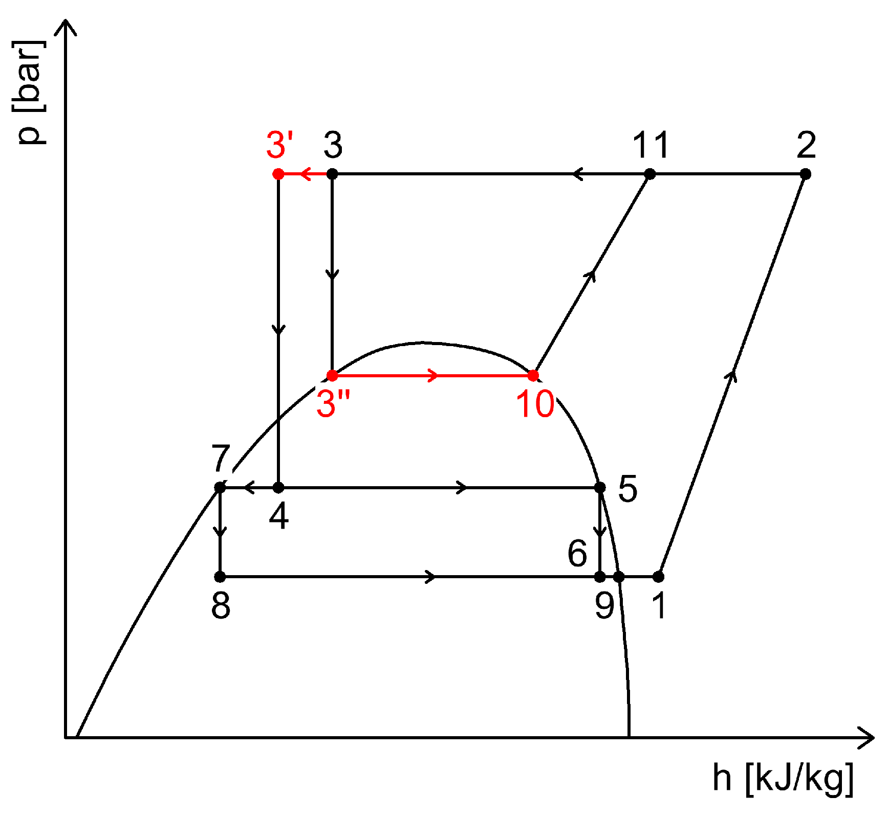
One of the most effective internal subcooling methods is the integrated mechanical subcooler [55]. This subcooler is a heat exchanger placed at the outlet of the gas cooler (see Figure 37). A small portion of the refrigerant, after being cooled in the gas cooler, is expanded (process 4–8) and directed into the subcooler. The remaining refrigerant flows through the subcooler and is cooled by the expanded CO2 (process 4–4′), thus undergoing the subcooling process. The portion of the refrigerant that absorbed heat from the mainstream is then compressed by an auxiliary compressor to the gas cooler pressure (process 9–10). The system’s p–h diagram, including the subcooling process, is illustrated in Figure 38.
An important advantage of this integrated subcooling system is the high efficiency of the auxiliary compressor, due to its higher suction pressure compared to the separator pressure. As a result, it operates with a lower compression ratio, making it more efficient than compressors in parallel compression setups.
Compared to a CO2 refrigeration system without subcooling, the use of an integrated mechanical subcooler can increase the coefficient of performance (COP) by up to 17.3%, under the following operating conditions: evaporation temperature of –10 °C, and a gas cooler outlet temperature of +30 °C [56].
In a study, Impact of an internal heat exchanger on a transcritical CO2 heat pump under optimal pressure conditions: Optimal-pressure performance of CO2 heat pump with IHX conducted an experiment regarding the Impact of an internal heat exchanger on a transcritical CO2 heat pump under optimal pressure conditions. Their work reveals that improving the efficiency of the intermediate heat exchanger, by increasing the exchange area, improves the system’s performance. For the cases with higher intermediate heat exchange area, the optimum pressure in the system is lower. For the heating experiments, the resulting thermodynamic COP is 7.55% higher in the case with IHX, while the effective COP increases by 4.26%. In consequence, the use of the Intermediate heat exchanger is recommended for the conditions analyzed [57].
Also, Experimental assessment of dedicated and integrated mechanical subcooling systems vs. parallel compression in transcritical CO2 refrigeration plants experimentally compared dedicated and integrated mechanical subcooling CO2 systems with a parallel compression baseline. Results showed COP increases up to 17.5% for the dedicated and up to 9.5% for the integrated configuration, confirming that both improve efficiency, with the dedicated subcooling system performing best overall [21].
The use of dedicated mechanical subcooling proved to be more energy-efficient than parallel compression in warm climates. However, when both approaches were combined, system performance improved significantly under the same conditions [58].
Another study, have experimentally analyzed three configurations of integrated mechanical subcooling transcritical CO2 cycles, differing in the refrigerant extraction point. Tests at various heat rejection temperatures showed that all configurations achieved similar COP values, with only minor differences in cooling capacity and subcooler performance [59].
For a better understanding and an overview image, Table 2 shows the heat recovery possibilities and a comparative analysis for different CO2 refrigeration systems presented in the previously mentioned literature.
To ensure a clear comparative understanding of the analyzed systems, Table 2 summarizes the reported performance indicators (COP range and relative improvement) for each CO2-based configuration. This presentation follows the approach used by Bellos et al. (2022), who compiled performance data from various polygeneration and refrigeration studies for enhanced readability and benchmarking purposes [60].
Table 2. Heat recovery possibilities and comparative analysis for different CO2 refrigeration systems.
Heat Recovery PossibilitiesCOP ImprovementExergy Efficiency ImprovementSystem Integration/ComplexityAdvantagesLimitationsCost (Estimated)
Heat Recovery for DHW, SH, ACHR from the high-pressure compressor discharge+20–40% [61,62]+10–45% [62,63]Medium
-
waste heat recovery
-
gas/electricity consumption for DHW or SH production is reduced
-
the indirect CO2 emissions is reduced
-
a compact system that produces both cooling and heating without additional sources
-
the temperature of the heat source is limited (depending on the subcritical/supercritical operating mode)
-
the complexity of automation increases
+5–25% investment cost, payback period 2–5 years
HR between the gas cooler and the intermediate separator receiver+10–25% [64,65]+5–20% [64]Medium
-
the need for additional air conditioning systems is reduced
-
a compact system that produces both cooling and air conditioning
-
lower performance at high ambient temperatures
-
the complexity of automation increases
+5–20% investment cost, payback period 2–5 years
Heat Recovery for Defrosting of EvaporatorsHR through defrosting evaporators with hot gases+5–10% estimated+5–15%
estimated
Medium
-
recovery of waste heat from compressor discharge gases
-
reduced defrost time [66]
-
very high defrosting process efficiency [66]
-
high operating pressures (safety measures, compatible equipment)
-
the high-precision control of the defrost cycle is required
+5–10% investment cost
HR through defrosting of evaporators with warm glycol+3–10% estimated+5–15%
estimated
Medium
-
recovery of waste heat from compressor discharge gases
-
uniform and controlled defrosting
-
reduced defrosting time
-
high defrosting process efficiency
-
an independent glycol loop is required
-
specially designed evaporators
-
the high-precision control of the defrost cycle is required
+5–15% investment cost, payback period 2–4 years
Heat recovery through Internal Heat ExchangersHR through internal heat exchangers acting as superheaters+3–17% [67,68]+5–20% [69]Low
-
the operation of the refrigeration system is optimized
-
superheating of the refrigerant at the compressor suction (preventing liquid refrigerant from entering the compressor)
-
improvement of the COP
-
reduction of exergy losses
-
additional pressure losses [67]
-
the defrost efficiency is strongly affected by both operational parameters and the type of refrigeration system [68]
+2–10% investment cost, payback period 2–4 years
HR via Internal Heat Exchangers with Subcooling Function+10–22% [70,71]+5–15% [71]Low
-
optimization of the refrigeration system operation
-
increase the cooling capacity
-
improvement of the COP
-
reduction of exergy losses
-
additional pressure losses [72]
-
the defrost efficiency is strongly affected by both operational parameters and the type of refrigeration system [68]
+2–8% investment cost, payback period 2–4 years

4. Energy Recovery Within CO2 Refrigeration Systems

4.1. Energy Recovery Using Ejectors

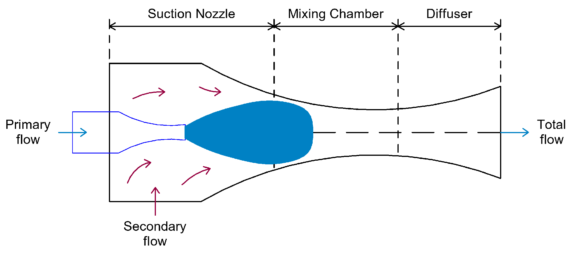
The ejector is a simple device composed of a nozzle, a mixing chamber, and a diffuser (Figure 39) [73], operating with a primary fluid flow and a secondary fluid flow.
The operating principle of the ejector is as follows: the primary fluid flow, at high pressure, expands and accelerates through a nozzle, entering a mixing chamber at supersonic speed. This generates a very low-pressure zone at the nozzle outlet. The high-velocity primary fluid entrains the secondary fluid into the mixing chamber. The mixing of the two fluid streams is considered complete at the end of the suction section, from which the flow exits at supersonic speed. In the mixing section, a shock wave is formed that causes a compression effect, reducing the flow velocity to subsonic levels. The compression of the fluid mixture is then completed as it passes through the diffuser [74].
Ejectors can be classified as follows:
  • According to nozzle position, two configurations are distinguished:
    • CPM (Constant Pressure Mixing)–the ejector with constant pressure mixing, where the nozzle outlet is located in the mixing chamber;
    • CAM (Constant Area Mixing)—the ejector with constant area mixing, where the nozzle outlet is placed in a constant-area section.
  • According to nozzle geometry, the ejector operation is influenced in two ways:
    • Convergent nozzle: the ejector operates in a subsonic regime, and the working fluid can reach at most sonic conditions at the nozzle outlet;
    • Convergent-divergent nozzle: the flow through the ejector can reach supersonic speeds.
  • According to the number of phases:
    • Single-phase ejectors: both primary and secondary fluid flows are in the same phase (gas–gas or liquid–liquid);
    • Two-phase ejectors: include condensing ejectors (where the primary fluid condenses inside the ejector—a highly complex modeling process) or ejectors where the flow at the outlet is in two phases [74].
In general, ejectors have three main applications in vapor compression refrigeration systems:
  • As a replacement for the compressor;
  • Integration between the compressor and condenser;
  • Substitution of conventional expansion devices, aiming to reduce interstage losses [75].
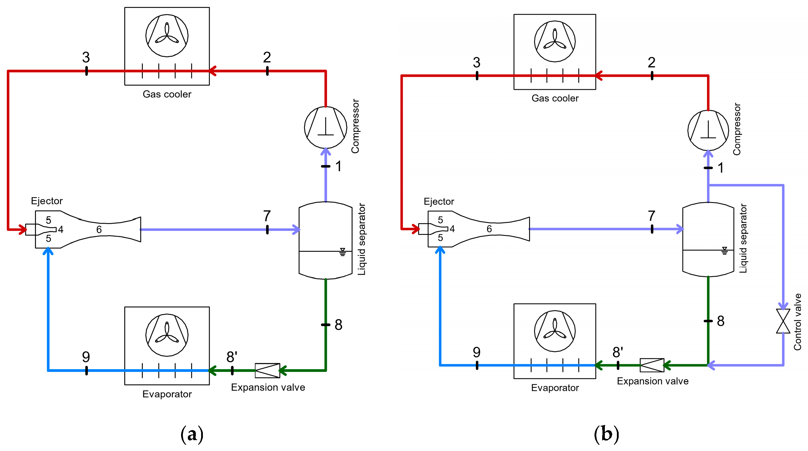
In transcritical CO2 refrigeration systems operating in a single stage, the ejector is introduced by replacing the high-pressure regulating valve (Figure 40a). With the help of the ejector, the suction pressure at the compressor increases compared to a standard cycle, resulting in higher system efficiency (less mechanical compression work required) [73]. However, the configuration shown in Figure 40a, although an improvement, presents difficulties in terms of controlling operating parameters [76].
Thus, in order to avoid issues related to the control of operating parameters, it was proposed to redirect a portion of the refrigerant flow—intended for compression—towards the evaporator using a control valve. This configuration (Figure 40b) resulted in an 18% increase in the coefficient of performance (COP) of the system compared to the single-stage CO2 refrigeration installation [77].
Moreover, following exergetic analyses, it was found that integrating ejectors within the refrigeration system significantly reduces exergy losses at the compressor level [78].
In commercial CO2 Booster refrigeration systems, the use of ejectors is an increasingly common solution for improving energy efficiency. In these systems, ejectors help reduce the mechanical energy required for compressing the refrigerant. Some strong arguments favoring the integration of ejectors in refrigeration systems include their low cost, the absence of moving parts during operation (which reduces the risk of failure), and the ability to handle two-phase refrigerant flows without damaging the system. All these reasons lead to the conclusion that using ejectors in these refrigeration systems represents the solution with the greatest potential for energy savings, especially in warm or very hot climates [79].
Ejectors recover mechanical work that normally would be lost during expansion in the high-pressure valve. The recovered mechanical work is applied to return the liquid and vapor from the medium-temperature (MT) compressor suction accumulator tank downstream of the MT evaporators back into the medium-pressure separator tank. Thanks to the ejectors and the suction accumulator tank, the suction pressure of the MT compressor in the refrigeration system increases by 6 K.
It has been found that this configuration reduces electrical energy consumption by 15–20% [80].
Research on integrating ejectors in CO2 Booster refrigeration systems with parallel compression concluded that the refrigeration system achieves energy consumption reductions of up to 12% [81]. Such a configuration allows for an efficiency increase of up to 30% compared to a simple CO2 Booster solution, especially during periods of high outdoor temperatures [82].
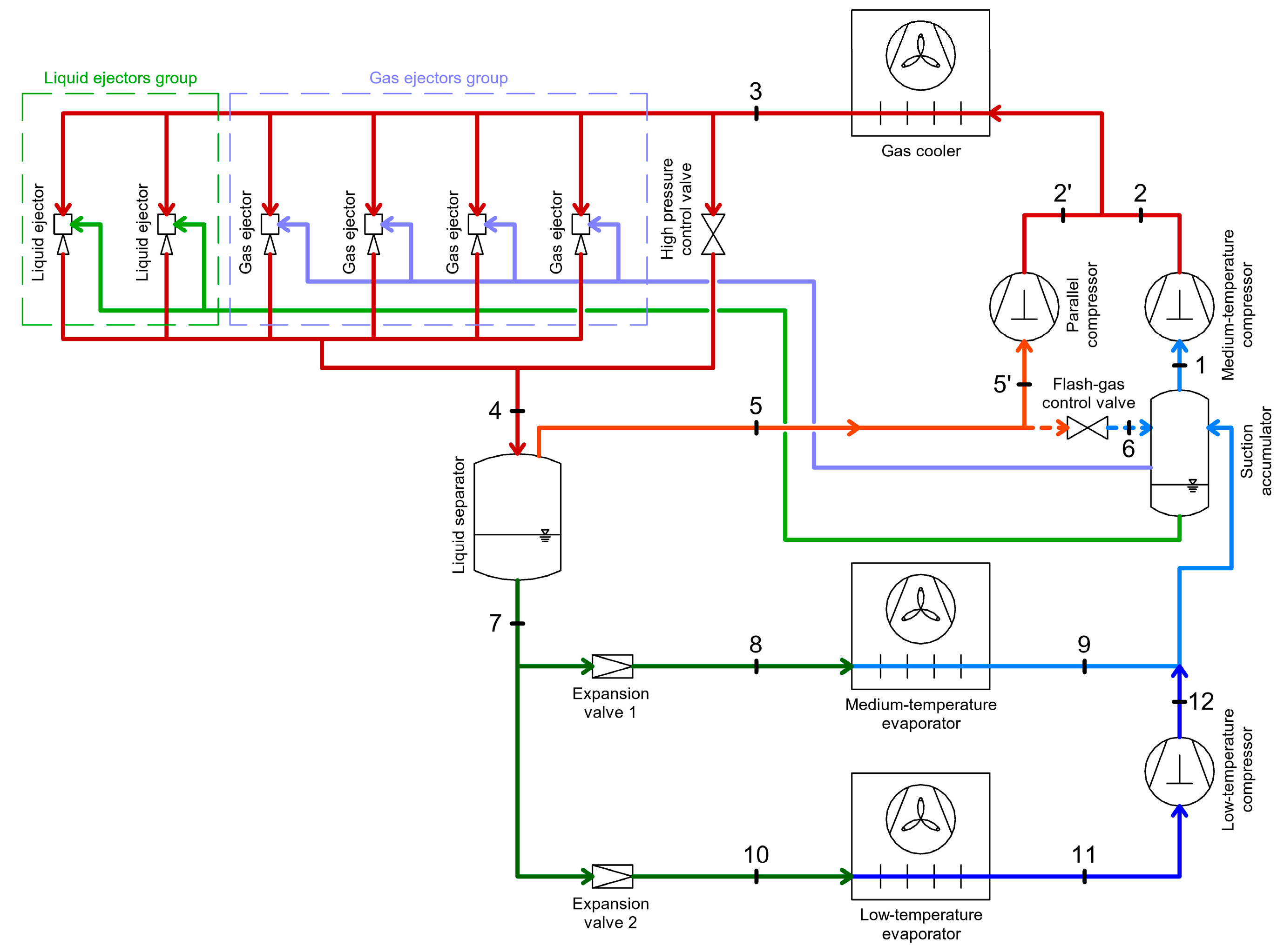
A commercial CO2 Booster refrigeration system equipped with parallel compression and ejectors (Figure 41) includes several vapor ejectors (usually 4 to 6) and several liquid ejectors (usually 2), all of which are fixed-geometry devices of various sizes connected in parallel [82].
Ejectors (regardless of type: gas or liquid) use as the primary flow the CO2 exiting the gas cooler, and as the secondary flow either gaseous CO2 (for gas ejectors) or liquid CO2 (for liquid ejectors) from the suction accumulator. The total amount of entrained refrigerant in each ejector is then directed into the separator receiver.
In this configuration, the parallel compressor compresses a significantly higher mass flow rate (compared to refrigeration systems without ejectors), while the mass flow rate of refrigerant drawn in by the MT compressors is reduced, resulting in substantial energy savings compared to simple CO2 Booster systems.
At least one gas ejector operates continuously, and the required capacity is constantly adjusted by switching operation between different gas ejectors or running multiple ejectors simultaneously. As for the liquid ejectors, their purpose is to reintroduce a portion of the liquid refrigerant back into the separator receiver to ensure a steady supply of liquid refrigerant to the evaporators [83].
Since CO2 Booster refrigeration systems with ejectors have achieved the best energy performance in warm climates, comparative studies have been conducted on various system configurations in terms of energy consumption. Thus, for a cooling capacity of 120 kW (refrigeration) and 25 kW (freezing), and under similar operating parameters, the annual energy consumption was evaluated (Figure 42) for four types of refrigeration systems in five Southern European cities with warm climates [83]: R404A (refrigeration system using R404A as the refrigerant), R744S (basic CO2 Booster system), R744 SP (CO2 Booster system with parallel compression), R744 SPE (CO2 Booster system with parallel compression and ejectors).
It has been found that the R744 SPE-type system shows an annual energy consumption reduction of up to 20% compared to the refrigeration system using R404A, up to 22% compared to the basic CO2 Booster refrigeration system, and up to 17% compared to the CO2 Booster system with parallel compression, under Southern European climate conditions and certain similar operating parameters.
An analysis was conducted on transcritical CO2 refrigeration systems with ejector and subcooling, driven by self-heat recovery, using different throttling devices. The study results showed COP improvements of 6–20% and increases in exergy efficiency of up to 20% compared to the reference cycles, demonstrating significant potential for enhancing energy efficiency in transcritical CO2 applications [84].
Another method of heat and energy recovery, which makes it possible to increase the efficiency of CO2 refrigeration cycles by using the energy of these cycles to operate heat-driven refrigeration systems. Another promising approach for improving the energy efficiency of CO2 refrigeration systems is the recovery and reuse of waste heat to drive thermally activated cooling systems. Chen et al. (2013) [85] investigated a hybrid ejector–CO2 compression cycle in which exhaust gas waste heat was utilized to operate an ejector subsystem providing subcooling for the CO2 vapor compression unit. The study demonstrated a 22% increase in overall COP compared to a single ejector cycle, confirming the potential of using low-grade thermal energy from CO2 systems to enhance their efficiency. Although this approach targets mainly vehicular and transport applications, its principle can be extended to stationary systems with available waste heat sources
Another approach to improving the efficiency of transcritical CO2 systems is the use of hybrid configurations that recover waste heat from the mechanical compression cycle to drive a thermally activated ejector cooling subsystem. Chen et al. (2017) [54] proposed such a hybrid CO2 transcritical mechanical compression–ejector cooling cycle, where the waste heat of the CO2 refrigerant is used to operate an ejector unit that provides additional subcooling. Their theoretical analysis indicated a 25–30% COP improvement compared with a conventional CO2 system, highlighting the potential of coupling thermal and mechanical refrigeration cycles to enhance overall system performance.

4.2. Energy Recovery Using Expanders

In vapor-compression refrigeration systems, the working fluid is compressed up to the condensation pressure using a compressor, then condenses in a heat exchanger called a condenser, undergoes expansion through an expansion device to reach a lower temperature and pressure, then enters the evaporator, where it absorbs heat from the cooled space, and the cycle repeats.
The expansion process is usually carried out by means of a capillary tube or a throttling valve. Studies have shown that this process is one of the main sources of irreversibility (loses) in vapor-compression refrigeration systems [86], and as a result, efforts are being made to find solutions that can reduce the losses resulting from this process.
To reduce these losses and recover expansion work, two devices can be implemented to replace the capillary tube or throttling valve: the ejector or the expansion turbine [87].
The ejector uses the expansion energy of the working fluid to raise its pressure at the compressor suction, thus reducing the compression ratio of the compressor, which leads to an increase in the coefficient of performance (COP) [73]. In general, the ejector is simpler to construct than an expansion turbine, but its implementation requires more complex modifications to the operating cycle.
Expansion turbines, on the other hand, are easier to install and at the same time more efficient than ejectors [88].
In Figure 43, the diagram of a vapor compression refrigeration system is presented, showing (a) the system using an expansion device and (b) the system where the expansion device is replaced by a detentor.
By using an expansion turbine, the drop in temperature and pressure occurs isentropically (process 3–4′), whereas with a throttling device, the process is isenthalpic (process 3–4).
The use of an expansion turbine brings benefits to the system by increasing the cooling capacity without altering the heat rejected in the condenser. At the same time, the mechanical work produced during the expansion in the turbine is recovered and used either to reduce the compressor motor’s electrical load or to generate electricity via a generator [88].
Expansion turbines have received increased research attention with the rise of transcritical CO2 refrigeration systems, in which very large pressure drops occur in the throttling devices due to the high operating pressure differences [89].
The first transcritical CO2 refrigeration system in which the possibility of replacing throttling devices with expansion turbines was studied was the single-stage system (Figure 44).
This system consists of a compressor, a gas cooler, a high-pressure regulating valve, a liquid receiver/separator, a throttling valve, and an evaporator.
This type of system is considered a two-stage throttling refrigeration system. The first throttling (process 3–4) is performed by the high-pressure regulating valve, which is a pressure-actuated expansion valve that controls the pressure in the gas cooler. The second throttling (process 4–5) is conducted using an electronic expansion valve, which is controlled based on the superheat level of the refrigerant at the evaporator outlet [90].
A liquid receiver is installed between the two valves. The state of the refrigerant at the outlet of the high-pressure valve, as well as its state at the inlet of the low-pressure expansion valve, are both on the saturation curve since the pressure inside the liquid receiver is continuously adjusted to the saturation pressure value [90]. Because of this, states 4 and 5 coincide on the p–h diagram.
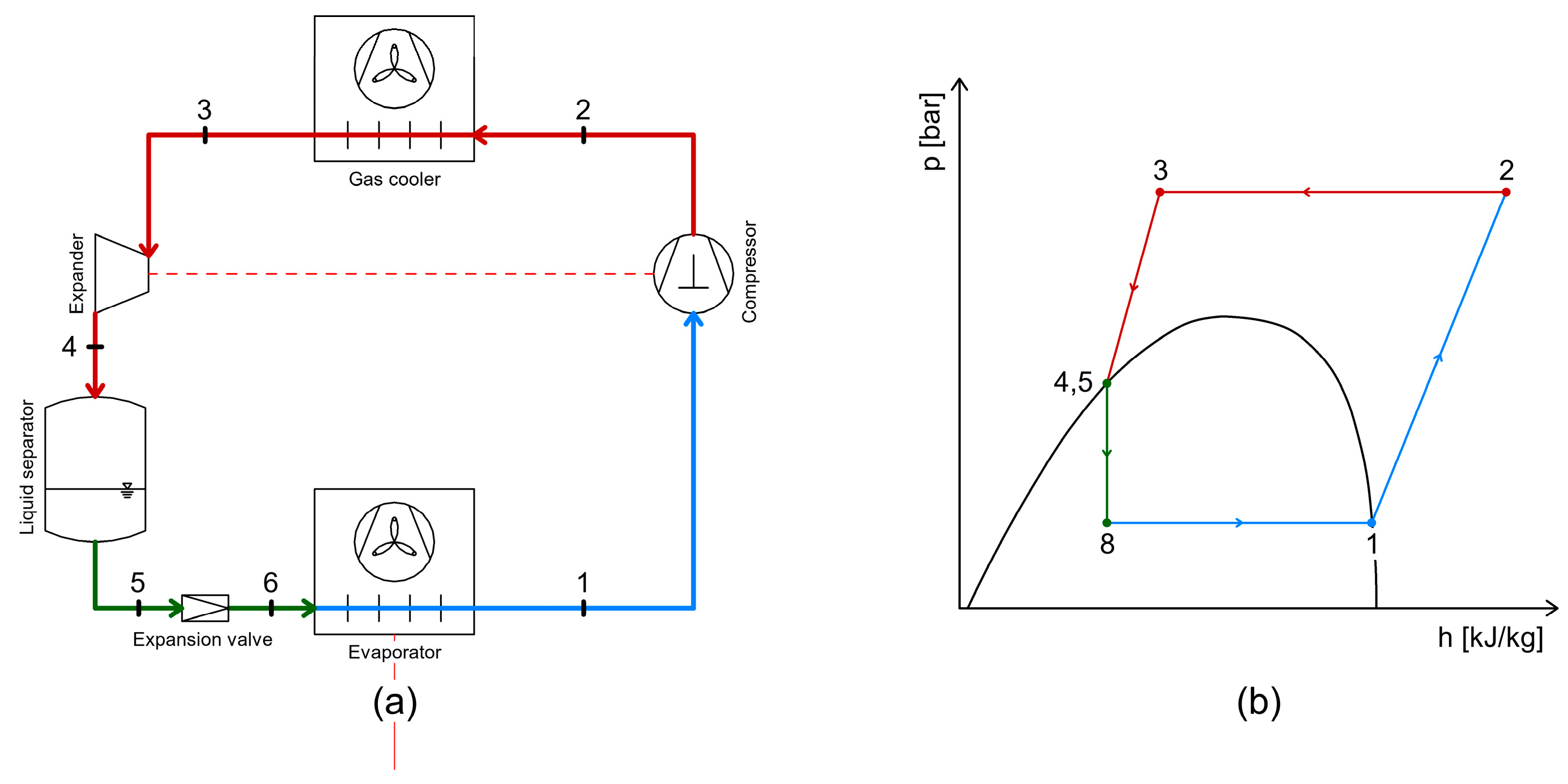
Based on this configuration of the single-stage CO2 refrigeration system, the possibility of replacing the throttling devices with expansion turbines was studied, starting with the replacement of the high-pressure regulating valve (Figure 45).
In this case, the expansion turbine operates between the high-pressure stage and the medium-pressure stage. The turbine is connected to an electric generator that converts the mechanical work produced by the expansion of the refrigerant into electrical energy. This electrical energy can be used to power the compressor of the refrigeration system [91].
It is observed that process 3–4 is now an isentropic process in which mechanical work is generated.
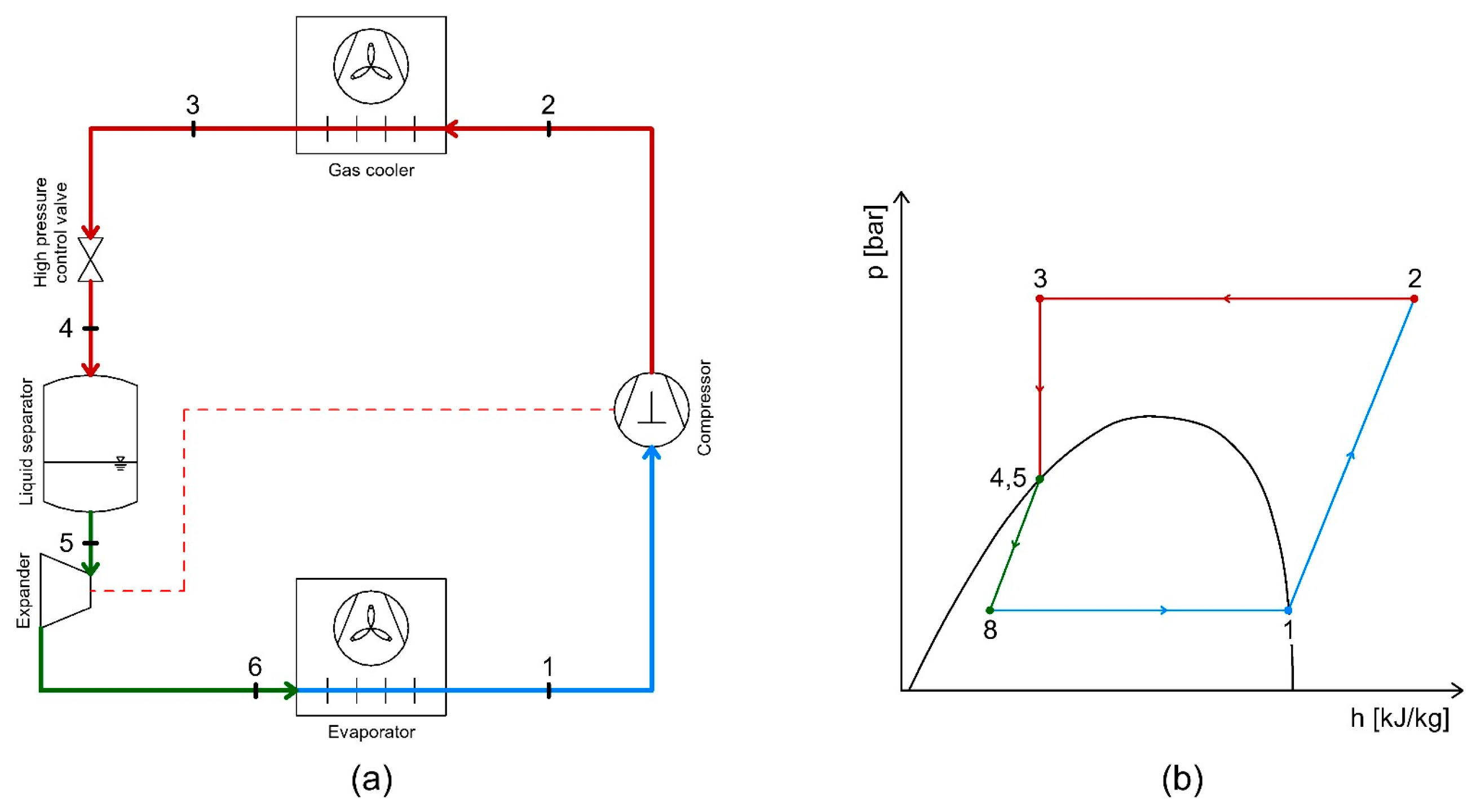
The second option is to replace the expansion valve with an expansion turbine (Figure 46). In this case, the expansion turbine operates between the medium-pressure stage and the low-pressure stage. As in the first case, the mechanical work produced by the expansion of the refrigerant is converted into electrical energy, which can be used to power the compressor of the refrigeration system.
It can be observed that, this time, the 5–6 process is an isentropic process in which mechanical work is generated.
Following the studies, it was found that the position of the expansion valve has a considerable influence on single-stage CO2 refrigeration systems. The highest values of the coefficient of performance (COP) are achieved when the expansion valve is positioned between the medium- and low-pressure stages, except in cases where the evaporation temperature is very high [91].
Table 3 presents synthetically and comparatively the most relevant aspects regarding the energy recovery possibilities from different CO2 refrigeration systems described in this section.

5. Conclusions

In the present work, heat and mechanical recovery possibilities in the case of industrial and commercial CO2 refrigeration systems are identified and described. The heat and mechanical power recovery solutions presented in the paper are the ones most suitable for practical applications and which can lead to higher energy efficiency of refrigeration systems and the building in which they operate.
Heat recovery can be implemented at the discharge of the high-temperature compressor to provide domestic hot water (70–50 °C) and/or water for direct space heating (50–40 °C). In transcritical CO2 booster refrigeration systems operating under normal conditions—without increasing the refrigerant mass flow rate or discharge pressure—heat recovery can reduce natural gas consumption for building heating by up to 48%, while simultaneously lowering operating costs by 6.2%. Furthermore, for the same system, increasing the discharge pressure can achieve a 32% reduction in the building’s overall energy consumption and, in certain cases, entirely eliminate the need for natural gas.
If the heat exchanger is mounted before the liquid separator, one can obtain low-temperature glycol 7 °C, which can partially or totally ensure the cooling demand of the air conditioning systems of the building in which the refrigeration system is mounted.
The hot refrigerant at a low-temperature compressor discharge can be used for the defrosting of low-temperature evaporators. This technical solution can lead to a COP increase of up to 8.5% of the booster system. The defrosting of low-temperature evaporator can be accomplished also with warm glycol. The glycol can be heated using a coil installed in the tank of the circuit that supplies hot water for heating the building where the refrigeration system is located. The temperature of the warm glycol is around 25 °C on the supply pipe and 15–18 °C on the return pipe. The heat recovery in the case of CO2 refrigeration systems can be achieved also through internal heat exchangers.
The internal heat exchangers can be a superheater, in which case the COP can increase to 35%. The superheater can be integrated into the CO2 refrigeration systems in different ways.
The internal heat exchanger can be a subcooler that could lead to a COP increase of 17% compared to CO2 refrigeration system without subcooling for an evaporating temperature of −10 °C and a 30 °C gas cooler outlet temperature.
In the case of CO2 refrigeration systems, besides heat recovery, mechanical energy can be implemented also. Mechanical energy can be recovered using ejectors or expanders. In the case of using ejectors in single-stage CO2 refrigeration systems, the energy consumption can be reduced by 20%.
For CO2 booster refrigeration systems with parallel compression, the use of ejectors can reduce energy consumption by up to 12%. Systems equipped with ejectors perform best in warm climates.
In the case of mechanical energy recovery using expanders, electrical energy can be generated and subsequently offset against the total energy consumption of the refrigeration system.

Author Contributions

Conceptualization, C.C.P. and H.P.; methodology, C.C.P. and H.P.; software, C.C.P.; validation, T.P. and V.A.; formal analysis, A.C.; investigation, A.C.; resources, V.A. and H.P.; data curation, V.A. and H.P.; writing—original draft preparation, C.C.P. and C.I.; writing—review and editing, C.C.P. and C.I.; visualization, H.P. and C.I.; supervision, T.P.; project administration, V.A.; funding acquisition, C.I. All authors have read and agreed to the published version of the manuscript.

Funding

This research received no external funding.

Data Availability Statement

The original contributions presented in the study are included in the article.

Acknowledgments

The APC was funded by the Romanian Ministry of Education and Research and National University of Science and Technology POLITEHNICA Bucharest through the PubArt programme.

Conflicts of Interest

The authors declare no conflicts of interest.

References

  1. Bruno, F.; Belusko, M.; Halawa, E. CO2 Refrigeration and Heat Pump Systems—A Comprehensive Review. Energies 2019, 12, 29–59. [Google Scholar] [CrossRef]
  2. Minetto, S.; Marinetti, S.; Saglia, P.; Masson, N.; Rossetti, A. Non-technological barriers to the diffusion of energy-efficient HVAC&R solutions in the food retail sector. Int. J. Refrig. 2018, 86, 422–434. [Google Scholar] [CrossRef]
  3. Galvez-Martos, J.-L.; Styles, D.; Schoenberger, H. Identified best environmental management practises to improve the energy performance of the retail trade sector in Europe. Energy Policy 2013, 63, 982–994. [Google Scholar] [CrossRef]
  4. Tassou, S.A.; Ge, Y.; Hadawey, A.; Marriott, D. Energy consumption and conservation in food retailing. Appl. Therm. Eng. 2011, 31, 147–156. [Google Scholar] [CrossRef]
  5. Metz, B.; Kuijpers, L.; Solomon, S.; Andersen, S.O.; Davidson, O.; Pons, J.; de Jager, D.; Kestin, T.; Manning, M.; Meyer, L. (Eds.) Safeguarding the Ozone Layer and the Global Climate System: Issues Related to Hydrofluorocarbons and Perfluorocarbons; IPCC/TEAP; Cambridge University Press: Cambridge, UK, 2005; p. 478. [Google Scholar]
  6. (EC) No 842/2006; Regulation (Eu) No 517/2014 of 16 April 2014 on Fluorinated Greenhouse Gases and Repealing Regulation. European Parliament and Council: Strasbourg, France, 2014.
  7. Lorentzen, G. Revival of carbon dioxide as a refrigerant. Int. J. Refrig. 1994, 17, 292–301. [Google Scholar] [CrossRef]
  8. Sooben, D.; Purohit, N.; Mohee, R.; Meunier, F. R744 refrigeration as an alternative for the supermarket sector in small tropical island developing states: The case of Mauritius. Int. J. Refrig. 2019, 103, 264–273. [Google Scholar] [CrossRef]
  9. Messineo, A. R744-R717 Cascade Refrigeration System: Performance Evaluation compared with a HFC Two-Stage System. Energy Procedia 2012, 14, 56–65. [Google Scholar] [CrossRef]
  10. Lee, T.S.; Liu, C.H.; Chen, T.W. Thermodynamic analysis of optimal condensing temperature of cascade-condenser in CO2/NH3 cascade refrigeration systems. Int. J. Refrig. 2006, 29, 1100–1108. [Google Scholar] [CrossRef]
  11. Getu, H.M.; Bansal, P.K. Modeling and performance analysis of evaporators in frozen food supermarket display cabinets at low temperatures. Int. J. Refrig. 2007, 30, 1227–1243. [Google Scholar] [CrossRef]
  12. Getu, H.M.; Bansal, P.K. Thermodynamic analysis of an R744/R717 cascade refrigeration system. Int. J. Refrig. 2008, 31, 45–54. [Google Scholar] [CrossRef]
  13. Emerson Climate Technologies. Commercial CO2 Refrigeration Systems—Guide for Subcritical and Transcritical CO2 Applications. 2016. Available online: https://www.emerson.com/documents/commercial-residential/commercial-co%E2%82%82-refrigeration-systems-en-us-181472.pdf (accessed on 20 June 2025).
  14. Rolfsman, L. Experiences from CO2 cascade plants. In Proceedings of the 21st IIR International Congress of Refrigeration, Washington, DC, USA, 17–22 August 2003. [Google Scholar]
  15. Vaishak, S.; Singha, P.; Dasgupta, M.S.; Hafner, A.; Widell, K.; Bhattacharyya, S.; Saini, S.K.; Arun, B.S.; Samuel, M.P.; Ninan, G. Performance analysis of a CO2/NH3 cascade refrigeration system with subcooling for low-temperature freezing applications. Int. J. Refrig. 2023, 153, 140–154. [Google Scholar] [CrossRef]
  16. Saini, S.K.; Dasgupta, M.S.; Widell, K.N.; Bhattacharyya, S. Comparative analysis of a few novel multi-evaporator CO2–NH3 cascade refrigeration system for seafood processing & storage. Int. J. Refrig. 2021, 131, 817–825. [Google Scholar] [CrossRef]
  17. Aleu, P. Makro Continues CO2 Installations in Latin America. 2019. Available online: https://archive.r744.com/articles/9267/makro_continues_co2_installations_in_latin_america?utm_source=chatgpt.com (accessed on 24 June 2025).
  18. Danfoss. Industrial Refrigeration—Ammonia and CO2 Applications (Application Handbook). 2010. Available online: www.danfoss.com/ir (accessed on 25 June 2025).
  19. Elbel, S.; Hrnjak, P. Ejector Refrigeration: An Overview of Historical and Present Developments with an Emphasis on Air-Conditioning Applications. 2008. Available online: https://docs.lib.purdue.edu/cgi/viewcontent.cgi?article=1883&context=iracc (accessed on 26 June 2025).
  20. Bai, T.; Shi, R.; Yu, J. Thermodynamic performance evaluation of an ejector-enhanced transcritical CO2 parallel compression refrigeration cycle. Int. J. Refrig. 2023, 149, 49–61. [Google Scholar] [CrossRef]
  21. Gholizadeh, T.; Rostami, S.; Arabkoohsar, A. Performance enhancement of transcritical CO2 compression cycles: Techno-environmental analysis and machine learning optimization. Appl. Therm. Eng. 2025, 266, 125591. [Google Scholar] [CrossRef]
  22. Zou, L.; Liu, Y.; Yu, J. Thermodynamic and environment analysis of a modified transcritical CO2 refrigeration cycle integrated with ejector and subcooler. Int. J. Refrig. 2025, 173, 123–138. [Google Scholar] [CrossRef]
  23. Li, L.; Tian, H.; Liu, K.; Wu, Y.; Wang, X.; Liang, X.; Shu, G. Optimum pressure control with three controllable ejectors of a CO2 multi-ejector refrigeration system. Int. J. Refrig. 2024, 157, 172–185. [Google Scholar] [CrossRef]
  24. Ge, Y.T.; Tassou, S.A. Thermodynamic analysis of transcritical CO2 booster refrigeration systems in supermarket. Energy Convers. Manag. 2011, 52, 1868–1875. [Google Scholar] [CrossRef]
  25. Li, W.; Korolija, I.; Tang, R.; Mumovic, D. High-fidelity model development of CO2 booster refrigeration systems in supermarkets using field measurements. Int. J. Refrig. 2025, 169, 152–165. [Google Scholar] [CrossRef]
  26. Sacasas, D.; Vega, J.; Cuevas, C. An annual energetic evaluation of booster and parallel refrigeration systems with R744 in food retail supermarkets. A Chilean perspective. Int. J. Refrig. 2022, 133, 326–336. [Google Scholar] [CrossRef]
  27. Syngounas, E.; Tsimpoukis, D.; Bellos, E.; Koukou, M.K.; Tzivanidis, C.; Vrachopoulos, M.G. Energy and exergy performance investigation of a transcritical CO2 vapor ejector-based refrigeration system for marine provision plants. Appl. Therm. Eng. 2025, 269, 126036. [Google Scholar] [CrossRef]
  28. Jiang, N.; Li, Y.; Dong, J.; Zhang, Y.; Hu, J.; Jiang, P. Dynamic simulation study on regulation characteristics of transcritical CO2 multi-ejector refrigeration system. Appl. Therm. Eng. 2024, 238, 121592. [Google Scholar] [CrossRef]
  29. Siemens Building Technologies. Heat Recovery in the Refrigeration Cycle. Brochure BO8RF Refrigeration Technology. Available online: http://www.bt.siemens.com.cn/partner/DownloadCenter/upload/20121217015059201.pdf (accessed on 27 June 2025).
  30. Sawalha, S. Investigation of heat recovery in CO2 trans-critical solution for supermarket refrigeration. Int. J. Refrig. 2013, 36, 145–156. [Google Scholar] [CrossRef]
  31. Sawalha, S.; Karampour, M. Supermarket Refrigeration and Heat Recovery Using CO2 as Refrigerant; Energimyndigheten: Eskilstuna, Sweden, 2014. [Google Scholar] [CrossRef]
  32. Polzot, A.; D’Agaro, P.; Cortella, G. Energy analysis of a transcritical CO2 supermarket refrigeration system with heat recovery. Energy Procedia 2017, 111, 648–657. [Google Scholar] [CrossRef]
  33. Danfoss. Heat Reclaim in Transcritical CO2 Systems (Application Guide). 2015. Available online: https://assets.danfoss.com/documents/latest/372092/AB167786419087en-000401.pdf?utm_source=chatgpt.com (accessed on 30 June 2025).
  34. Escriva, E.J.S.; Acha, S.; Le Brun, N.; Francés, V.S.; Ojer, J.M.P.; Markides, C.N.; Shah, N. Modelling of a real CO2 booster installation and evaluation of control strategies for heat recovery applications in supermarkets. Int. J. Refrig. 2019, 107, 288–300. [Google Scholar] [CrossRef]
  35. Thanasoulas, S. Investigation of heat recovery in CO2 refrigeration cycles for supermarkets: A mechanism for determining optimal discharge pressure. Appl. Therm. Eng. 2025, 274, 1358–4311. [Google Scholar] [CrossRef]
  36. Giunta, F.; Sawalha, S. Techno-economic analysis of heat recovery from supermarket’s CO2 refrigeration systems to district heating networks. Appl. Therm. Eng. 2021, 193, 239–257. [Google Scholar] [CrossRef]
  37. Steuer, D.; Arias, J.; Sawalha, S. Techno-economic evaluation of heat recovery from supermarket refrigeration systems: A case study of four real-world installations. Appl. Therm. Eng. 2025, 281, 798–811. [Google Scholar] [CrossRef]
  38. Aboaltabooq, M.H.K.; Prisecaru, T.; Pop, H.; Apostol, V.; Prisecaru, M.; Popescu, G.; Pop, E.; Alexandru, A.-M.; Petcu, C.; Ciobanu, C. Effect of variable heat input on the heat transfer characteristics in an Organic Rankine Cycle system. Renew. Energy Environ. Sustain. 2016, 1, 13. [Google Scholar] [CrossRef]
  39. Karampour, M.; Sawalha, S. Theoretical analysis of CO2 trans-critical system with parallel compression for heat recovery and air conditioning in supermarkets. In Proceedings of the 24th IIR International Congress of Refrigeration—ICR2015, Yokohama, Japan, 16–22 August 2015; Available online: https://www.researchgate.net/publication/281583937 (accessed on 1 July 2025).
  40. Azzolin, M.; Cattelan, G.; Dugaria, S.; Minetto, S.; Calabrese, L.; Del Col, D. Integrated CO2 systems for supermarkets: Field measurements and assessment for alternative solutions in hot climate. Appl. Therm. Eng. 2021, 187, 116560. [Google Scholar] [CrossRef]
  41. Hoffenbecker, N.; Klein, S.A.; Reindl, D.T. Hot gas defrost model development and validation. Int. J. Refrig. 2005, 28, 605–615. [Google Scholar] [CrossRef]
  42. Amer, M.; Wang, C.C. Review of defrosting methods. Renew. Sustain. Energy Rev. 2017, 73, 53–74. [Google Scholar] [CrossRef]
  43. Klein, S.A.; Reindl, D.T.; Brownell, K. Refrigeration system performance using liquid-suction heat exchangers. Int. J. Refrig. 2000, 23, 588–596. [Google Scholar] [CrossRef]
  44. Domanski, P.A.; Didion, D.A.; Doyle, J.P. Evaluation of suction-line/liquid-line heat exchange in the refrigeration cycle. Int. J. Refrig. 1994, 17, 487–493. [Google Scholar] [CrossRef]
  45. Aprea, C.; Ascani, M.; Rossi, F. A criterion for predicting the possible advantage of adopting a suction/liquid heat exchanger in refrigerating system. Appl. Therm. Eng. 1999, 19, 329–336. [Google Scholar] [CrossRef]
  46. Torrella, E.; Sánchez, D.; Llopis, R.; Cabello, R. Energetic evaluation of an internal heat exchanger in a CO2 transcritical refrigeration plant using experimental data. Int. J. Refrig. 2011, 34, 40–49. [Google Scholar] [CrossRef]
  47. Rigola, J.; Ablanque, N.; Pérez-Segarra, C.D.; Oliva, A. Numerical simulation and experimental validation of internal heat exchanger influence on CO2 trans-critical cycle performance. Int. J. Refrig. 2010, 33, 664–674. [Google Scholar] [CrossRef]
  48. Sánchez, D.; Patiño, J.; Llopis, R.; Cabello, R.; Torrella, E.; Fuentes, F.V. New positions for an internal heat exchanger in a CO2 supercritical refrigeration plant. Experimental analysis and energetic evaluation. Appl. Therm. Eng. 2014, 63, 129–139. [Google Scholar] [CrossRef]
  49. Llopis, R.; Nebot-Andrés, L.; Sánchez, D.; Catalán-Gil, J.; Cabello, R. Subcooling methods for CO2 refrigeration cycles: A review. Int. J. Refrig. 2018, 93, 85–107. [Google Scholar] [CrossRef]
  50. Llopis, R.; Cabello, R.; Sánchez, D.; Torrella, E. Energy improvements of CO2 transcritical refrigeration cycles using dedicated mechanical subcooling. Int. J. Refrig. 2015, 55, 129–141. [Google Scholar] [CrossRef]
  51. Schoenfield, J.; Muehlbauer, J.; Hwang, Y.; Radermacher, R. Integration of a thermoelectric subcooler into a carbon dioxide transcritical vapor compression cycle refrigeration system. In Proceedings of the International Refrigeration and Air Conditioning Conference, West Lafayette, IN, USA, 14–17 July 2008; p. 903. Available online: http://docs.lib.purdue.edu/iracc/903 (accessed on 3 July 2025).
  52. Arora, A.; Singh, N.K.; Monga, S.; Kumar, O. Energy and exergy analysis of a combined transcritical CO2 compression refrigeration and single effect H2O-LiBr vapour absorption system. Int. J. Exergy 2011, 9, 453–471. [Google Scholar] [CrossRef]
  53. Mazzola, D.; Sheehan, J.; Bortoluzzi, D.; Smitt, G.; Orlandi, M. Supermarket application. Effects of sub-cooling on real R744 based trans-critical plants in warm and hot climate. In Proceedings of the 12th IIR Gustav Lorentzen Conference on Natural Refrigerants (GL2016), Edinburgh, UK, 21–24 August 2016; pp. 551–558. [Google Scholar] [CrossRef]
  54. Chen, G.; Volovyk, O.; Zhu, D.; Ierin, V.; Shestopalov, K. Theoretical analysis and optimization of a hybrid CO2 transcritical mechanical compression—Ejector cooling cycle. Int. J. Refrig. 2017, 74, 86–94. [Google Scholar] [CrossRef]
  55. Kantchev, J.; Lesage, G. Mechanical Subcooling of Transcritical R-744 Refrigeration Systems with Heat Pump Heat Reclaim and Floating Head Pressure. European Patent Application EP 2 632 561 A3, 20 November 2013. Available online: https://patentimages.storage.googleapis.com/cf/fe/95/6b7e456e3a9165/EP2631561A3.pdf (accessed on 7 July 2025).
  56. Cecchinato, L.; Chiarello, M.; Corradi, M.; Fornasieri, E.; Minetto, S.; Stringari, P.; Zilio, C. Thermodynamic analysis of different two-stage transcritical carbon dioxide cycles. Int. J. Refrig. 2009, 32, 1058–1067. [Google Scholar] [CrossRef]
  57. Corberán, J.M.; Martínez-Galván, A.; Martínez-Ballester, S.; Gonzálvez-Maciá, J.; Alias, C. Impact of an internal heat exchanger on a transcritical CO2 heat pump under optimal pressure conditions: Optimal-pressure performance of CO2 heat pump with IHX. Int. J. Refrig. 2008, 31, 1059–1067. [Google Scholar] [CrossRef]
  58. Song, Y.; Cui, C.; Yin, X.; Cao, F. Advanced development and application of transcritical CO2 refrigeration and heat pump technology—A review. Energy Rep. 2022, 8, 7840–7869. [Google Scholar] [CrossRef]
  59. Nebot-Andrés, L.; Cabello, R.; Sánchez, D.; Catalán-Gil, J.; Llopis, R.; Torrella, E. Experimental assessment of different extraction points for the integrated mechanical subcooling system of a CO2 transcritical plant. Appl. Therm. Eng. 2021, 197, 117370. [Google Scholar] [CrossRef]
  60. Bellos, E.; Zafar Said, Z.; Lykas, P.; Tzivanidis, C. A review of polygeneration systems with CO2 working fluid. Therm. Sci. Eng. Progress. 2022, 31, 101325. [Google Scholar] [CrossRef]
  61. Li, W.; Korolija, I.; Tang, R.; Mumovic, D. Performance analysis of heat recovery in CO2 refrigeration systems for heating electrification in supermarkets. Appl. Energy 2025, 383, 125461. [Google Scholar] [CrossRef]
  62. Aghagoli, A.; Sorin, M.; Khennich, M. Exergy efficiency and COP improvement of a CO2 transcritical heat pump system by replacing an expansion valve with a Tesla turbine. Energies 2022, 15, 4973. [Google Scholar] [CrossRef]
  63. Gambini, M.; Manno, M.; Vellini, M. Energy and exergy analysis of transcritical CO2 cycles for heat pump applications. Sustainability 2024, 16, 7511. [Google Scholar] [CrossRef]
  64. Shi, W.; Chang, H.; Zhou, J.; Mu, B.; Quan, S.; Pan, L. Research progress on CO2 transcritical cycle technology for building heating and cooling applications. Buildings 2025, 15, 2952. [Google Scholar] [CrossRef]
  65. Karampour, M.; Sawalha, S. Integration of heating and air conditioning into a CO2 transcritical booster system with parallel compression. Part II: Performance analysis based on field measurements. In Proceedings of the 12th IIR Gustav Lorentzen Conference on Natural Refrigerants (GL2016), Edinburgh, UK, 21–24 August 2016. [Google Scholar] [CrossRef]
  66. Wang, Y.; Ye, Z.; Pan, Z.; Zhao, J.; Hu, B.; Cao, F. Hot-gas bypass defrosting method and analysis of defrosting time for transcritical CO2 heat pump. J. Shanghai Jiaotong Univ. 2019, 53, 1367–1374. [Google Scholar] [CrossRef]
  67. Zhang, Z.; Tian, L.; Chen, Y.; Tong, L. Effect of an internal heat exchanger on performance of the transcritical carbon dioxide refrigeration cycle with an expander. Entropy 2014, 16, 5919–5934. [Google Scholar] [CrossRef]
  68. Shi, B.; Chen, M.; Chi, W.; Yang, Q.; Liu, G.; Zhao, Y.; Li, L. Effects of internal heat exchanger on two-stage compression transcritical CO2 refrigeration cycle combined with expander and intercooling. Energies 2023, 16, 115. [Google Scholar] [CrossRef]
  69. Xiang, Q.; Wang, D.; Jin, Z.; Wang, J.; Zhang, G.; Li, H. A comprehensive investigation on the effect of internal heat exchanger based on a novel evaluation method in the transcritical CO2 heat pump system. Renew. Energy 2021, 178, 574–586. [Google Scholar] [CrossRef]
  70. Nebot-Andrés, L.; Calleja-Anta, D.; Sánchez, D.; Cabello, R.; Llopis, R. Thermodynamic analysis of a CO2 refrigeration cycle with integrated mechanical subcooling. Energies 2020, 13, 4. [Google Scholar] [CrossRef]
  71. Satrústegui, Á.; Aranguren, P.; Araiz, M.; Sánchez, D.; Cabello, R.; Astrain, D. Experimental evaluation of a transcritical CO2 refrigeration facility working with an internal heat exchanger and a thermoelectric subcooler: Performance assessment and comparative. Int. J. Refrig. 2022, 141, 66–75. [Google Scholar] [CrossRef]
  72. Wang, J.; Belusko, M.; Evans, M.; Liu, M.; Zhao, C.; Bruno, F. A comprehensive review and analysis on CO2 heat pump water heaters. Energy Convers. Manag. X 2022, 15, 100277. [Google Scholar] [CrossRef]
  73. Besagni, G.; Mereu, R.; Inzoli, F. Ejector refrigeration: A comprehensive review. Renew. Sustain. Energy Rev. 2016, 53, 373–407. [Google Scholar] [CrossRef]
  74. Chen, X.; Omer, S.; Worall, M.; Riffat, S. Recent developments in ejector refrigeration technologies. Renew. Sustain. Energy Rev. 2013, 19, 629–651. [Google Scholar] [CrossRef]
  75. Sumeru, K.; Nasution, H.; Ani, F. A review on two-phase ejector as an expansion device in vapor compression refrigeration cycle. Renew. Sustain. Energy Rev. 2012, 16, 4927–4937. [Google Scholar] [CrossRef]
  76. Sarkar, J. Ejector enhanced vapor compression refrigeration and heat pump systems—A review. Renew. Sustain. Energy Rev. 2012, 16, 6647–6659. [Google Scholar] [CrossRef]
  77. Li, D.; Groll, E.A. Transcritical CO2 refrigeration cycle with ejector-expansion device. Int. J. Refrig. 2005, 28, 766–773. [Google Scholar] [CrossRef]
  78. Deng, J.-Q.; Jiang, P.-X.; Lu, T.; Lu, W. Particular characteristics of transcritical CO2 refrigeration cycle with an ejector. Appl. Therm. Eng. 2007, 27, 381–388. [Google Scholar] [CrossRef]
  79. Haida, M.; Banasiak, K.; Smolka, J.; Hafner, A.; Eikevik, T.M. Experimental analysis of the R744 vapour compression rack equipped with the multi-ejector expansion work recovery module. Int. J. Refrig. 2016, 64, 93–107. [Google Scholar] [CrossRef]
  80. Schönenberger, J. Experience with R744 refrigerating systems and implemented multi ejectors and liquid overfeed. In Proceedings of the 12th IIR Gustav Lorentzen Natural Working Fluids Conference, Edinburgh, UK, 21–24 August 2016. ID: 1107. [Google Scholar]
  81. Hafner, A.; Shönenberger, J.; Banasiak, K.; Girotto, S. R744 ejector supported parallel vapour compression system. In Proceedings of the 3rd IIR International Conference on Sustainability and Cold Chain, London, UK, 23–25 June 2014. ID: 129. [Google Scholar]
  82. Hafner, A.; Försterling, S.; Banasiak, K. Multi-ejector concept for R-744 supermarket refrigeration. Int. J. Refrig. 2014, 43, 1–13. [Google Scholar] [CrossRef]
  83. Gullo, P.; Hafner, A.; Cortella, G. Multi-ejector R744 booster refrigerating plant and air conditioning system integration—A theoretical evaluation of energy benefits for supermarket applications. Int. J. Refrig. 2017, 75, 164–176. [Google Scholar] [CrossRef]
  84. Lv, J.; Lv, D.; Yang, Q.; Zhao, Y.; Liu, G.; Li, L. Comparative performance analysis of a self-heat recuperation driven ejector subcooling transcritical CO2 refrigeration systems using different throttling devices. Int. J. Refrig. 2025, 134, 106–119. [Google Scholar] [CrossRef]
  85. Chen, X.; Worall, M.; Omer, S.; Su, Y.; Riffat, S. Theoretical studies of a hybrid ejector CO2 compression cooling system for vehicles and preliminary experimental investigations of an ejector cycle. Appl. Energy 2013, 102, 931–942. [Google Scholar] [CrossRef]
  86. Ahamed, J.U.; Saidur, R.; Masjuki, H.H. A review on exergy analysis of vapor compression refrigeration system. Renew. Sustain. Energy Rev. 2011, 15, 1593–1600. [Google Scholar] [CrossRef]
  87. Murthy, A.A.; Subiantoro, A.; Norris, S.; Fukuta, M. A review on expanders and their performance in vapour compression refrigeration systems. Int. J. Refrig. 2019, 106, 427–446. [Google Scholar] [CrossRef]
  88. Elbel, S.; Lawrence, N. Review of recent developments in advanced ejector technology. Int. J. Refrig. 2016, 62, 1–18. [Google Scholar] [CrossRef]
  89. Lorentzen, G.; Pettersen, J. A new, efficient and environmentally benign system for car air-conditioning. Int. J. Refrig. 1993, 16, 4–12. [Google Scholar] [CrossRef]
  90. Kim, M.H.; Pettersen, J.; Bullard, C.W. Fundamental process and system design issues in CO2 vapor compression systems. Progress. Energy Combust. Sci. 2004, 30, 119–174. [Google Scholar] [CrossRef]
  91. Dai, B.; Liu, S.; Zhu, K.; Sun, Z.; Ma, Y. Thermodynamic performance evaluation of transcritical carbon dioxide refrigeration cycle integrated with thermoelectric subcooler and expander. Energy 2017, 122, 787–800. [Google Scholar] [CrossRef]
  92. Söylemez, E.; Hafner, A.; Schlemminger, C.; Kriezi, E.E.; Khorshidi, V. Performance analysis of an integrated CO2 refrigeration system with multi-ejectors installed in a supermarket. Energies 2022, 15, 3142. [Google Scholar] [CrossRef]
  93. Elbarghthi, A.F.A.; Dvořák, V. Evaluation of various ejector profiles on CO2 transcritical refrigeration system performance. Entropy 2022, 24, 1173. [Google Scholar] [CrossRef]
  94. Zheng, L.; Zhang, Y.; Hao, L.; Lian, H.; Deng, J.; Lu, W. Modelling, optimization, and experimental studies of refrigeration CO2 ejectors: A review. Mathematics 2022, 10, 4325. [Google Scholar] [CrossRef]
  95. Zhang, Z.; Tong, L.; Wang, X. Thermodynamic analysis of double-stage compression transcritical CO2 refrigeration cycles with an expander. Entropy 2015, 17, 2544–2555. [Google Scholar] [CrossRef]
  96. Mei, S.; Liu, Z.; Liu, X. Research progress and applications of transcritical carbon dioxide heat pumps: A review. Clean Energy Sci. Technol. 2023, 1, 118. [Google Scholar] [CrossRef]
  97. Taslimitaleghani, S.; Sorin, M.; Poncet, S. Energy and exergy efficiencies of different configurations of the ejector-based CO2 refrigeration systems. Int. J. Energy Prod. Manag. 2018, 3, 22–33. [Google Scholar] [CrossRef]
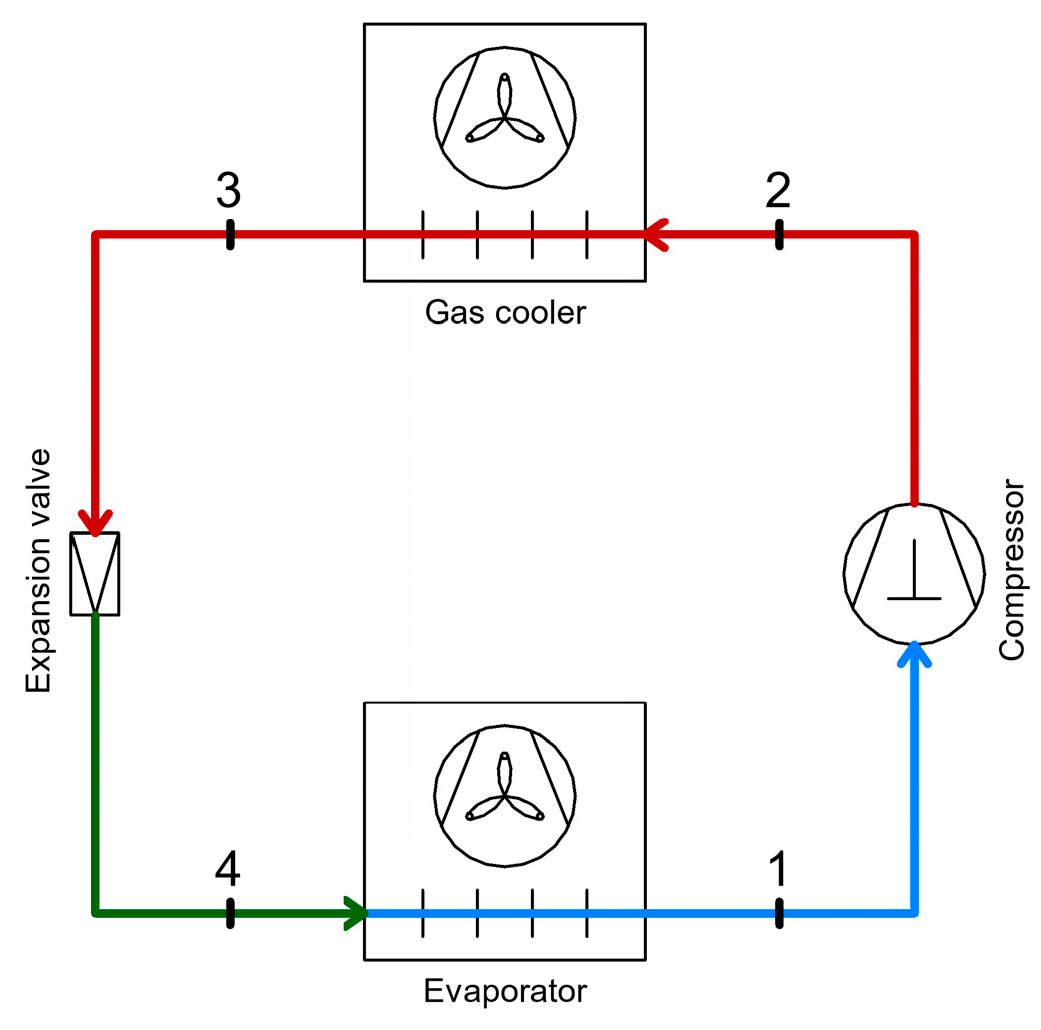
Figure 1. Diagram of a simple CO2 refrigeration system operating in transcritical mode.
Inventions 10 00105 g001
Figure 2. Operating cycle represented on the pressure–enthalpy (p–h) diagram for a simple transcritical CO2 refrigeration system.
Inventions 10 00105 g002
Figure 3. Schematic Diagram of the R717–R744 Cascade Refrigeration System.
Inventions 10 00105 g003
Figure 4. Operating Cycle on the p–h Diagram of the Cascade Refrigeration System Using R717–R744.
Inventions 10 00105 g004
Figure 5. Diagram of the Single-Stage CO2 Refrigeration System.
Inventions 10 00105 g005
Figure 6. Operating Cycle on the p–h Diagram of the Single-Stage CO2 Refrigeration System.
Inventions 10 00105 g006
Figure 7. Diagram of the Single-Stage CO2 Refrigeration System with Parallel Compression.
Inventions 10 00105 g007
Figure 8. Operating Cycle on the p–h Diagram of the Single-Stage CO2 Refrigeration System with Parallel Compression.
Inventions 10 00105 g008
Figure 9. Ejector diagram [1].
Inventions 10 00105 g009
Figure 10. Diagram of the single-stage CO2 refrigeration system with ejector.
Inventions 10 00105 g010
Figure 11. Operating cycle in the p–h diagram of the single-stage CO2 refrigeration system with ejector.
Inventions 10 00105 g011
Figure 12. Diagram of the CO2 Booster refrigeration system.
Inventions 10 00105 g012
Figure 13. Operating cycle in the p–h diagram of the CO2 Booster refrigeration system.
Inventions 10 00105 g013
Figure 14. Diagram of the CO2 Booster refrigeration system with parallel compression.
Inventions 10 00105 g014
Figure 15. Operating cycle in the p–h diagram of the CO2 Booster refrigeration system with parallel compression.
Inventions 10 00105 g015
Figure 16. Diagram of the CO2 Booster Refrigeration System with Parallel Compression and Ejector.
Inventions 10 00105 g016
Figure 17. Schematic of the Transcritical CO2 Booster System Equipped with Heat Recovery for Domestic Hot Water and Space Heating.
Inventions 10 00105 g017
Figure 18. Operating Cycle in the p–h Diagram of the Transcritical CO2 Booster System Equipped with Heat Recovery for Domestic Hot Water and Space Heating.
Inventions 10 00105 g018
Figure 19. CO2 Booster System Operating in Winter Conditions (Subcritical Operation).
Inventions 10 00105 g019
Figure 20. Heat recovery in the case of increasing the compressor discharge pressure.
Inventions 10 00105 g020
Figure 21. 100% heat recovery using the gas cooler bypass method.
Inventions 10 00105 g021
Figure 22. Heat recovery for providing cooling capacity within the air handling system.
Inventions 10 00105 g022
Figure 23. Diagram of the CO2 Booster refrigeration system with an intercooler on the low-pressure stage.
Inventions 10 00105 g023
Figure 24. Hot gas defrosting process when the evaporator design features a common coil for both refrigeration and defrosting processes.
Inventions 10 00105 g024
Figure 25. Hot gas defrosting process when the evaporator design features separate coils for refrigeration and defrosting processes.
Inventions 10 00105 g025
Figure 26. Defrosting method of evaporators using warm glycol.
Inventions 10 00105 g026
Figure 27. Diagram of a simple CO2 refrigeration system operating in transcritical mode with superheating.
Inventions 10 00105 g027
Figure 28. Operating cycle in the p–h diagram of the simple CO2 refrigeration system in transcritical mode with superheating.
Inventions 10 00105 g028
Figure 29. Diagram of a single-stage CO2 refrigeration system with a superheater installed at the gas cooler outlet.
Inventions 10 00105 g029
Figure 30. Operating cycle on the p–h diagram of the single-stage CO2 refrigeration system with a superheater installed at the gas cooler outlet.
Inventions 10 00105 g030
Figure 31. Diagram of the single-stage CO2 refrigeration system with the superheater installed at the outlet of the separator vessel.
Inventions 10 00105 g031
Figure 32. Operating cycle on the p–h diagram of the single-stage CO2 refrigeration system with the superheater installed at the outlet of the separator vessel.
Inventions 10 00105 g032
Figure 33. Diagram of the single-stage CO2 refrigeration system with two superheaters.
Inventions 10 00105 g033
Figure 34. Operating cycle in the p–h diagram of the single-stage CO2 refrigeration system with two superheaters.
Inventions 10 00105 g034
Figure 35. Diagram of the CO2 Booster refrigeration system with parallel compression and internal heat exchangers functioning as superheaters.
Inventions 10 00105 g035
Figure 36. Operating cycle in the p–h diagram of the CO2 Booster refrigeration system with parallel compression and internal heat exchangers.
Inventions 10 00105 g036
Figure 37. Schematic of the single-stage CO2 refrigeration system with integrated mechanical subcooler.
Inventions 10 00105 g037
Figure 38. The operating cycle on the p–h diagram of the single-stage CO2 refrigeration system with integrated mechanical subcooler.
Inventions 10 00105 g038
Figure 39. Ejector diagram [1].
Inventions 10 00105 g039
Figure 40. (a) Diagram of a single-stage CO2 refrigeration system with an ejector. (b) Diagram of a single-stage CO2 refrigeration system with an optimized ejector.
Inventions 10 00105 g040
Figure 41. Diagram of the CO2 Booster refrigeration system with parallel compression and ejector.
Inventions 10 00105 g041
Figure 42. Annual energy consumption [MWh/year] of refrigeration systems in warm climates of Southern Europe [83].
Inventions 10 00105 g042
Figure 43. Diagram of the refrigeration system with a throttling device (a) and with an expansion turbine (b), and the operating cycle on the p–h diagram (c).
Inventions 10 00105 g043
Figure 44. Diagram of the single-stage CO2 refrigeration system (a) and the operating cycle on the p–h diagram (b).
Inventions 10 00105 g044
Figure 45. Diagram of the single-stage CO2 refrigeration system (a) and its operating cycle on the p–h diagram (b), with the expansion valve positioned between the high-pressure and medium-pressure stages.
Inventions 10 00105 g045
Figure 46. Diagram of the single-stage CO2 refrigeration system (a) and the operating cycle on the p–h diagram (b), with the expansion valve positioned between the medium- and low-pressure stages.
Inventions 10 00105 g046
Table 1. Comparative table of CO2 refrigeration systems with possible methods of heat and energy recovery.
Heat Recovery for DHW, SH, ACHeat Recovery for Defrosting of EvaporatorsHeat Recovery Through Internal Heat ExchangersEnergy Recovery
HR from the High-Pressure Compressor DischargeHR Between the Gas Cooler and the Intermediate Separator ReceiverHR Through Defrosting Evaporators with Hot GasesHR Through Defrosting of Evaporators with Hot GlycolHR Through Internal Heat Exchangers Acting as SuperheatersHR via Internal Heat Exchangers with Subcooling FunctionEnergy Recovery Using EjectorsEnergy Recovery Using Expansion Turbines
Cascade Refrigeration System Using CO2 and Ammonia
Single-Stage CO2 Refrigeration System
Single-Stage CO2 Refrigeration System with Parallel Compression
Single-Stage CO2 Refrigeration System with Ejector
CO2 Booster Refrigeration System
CO2 Booster Refrigeration System with Parallel Compression
CO2 Booster Refrigeration System with Parallel Compression and Ejector
Table 3. Energy recovery possibilities and comparative analysis for different CO2 refrigeration systems.
Energy Recovery PossibilitiesCOP ImprovementExergy Efficiency ImprovementSystem Integration/ComplexityAdvantagesLimitationsCost (Estimated)
Energy RecoveryEnergy Recovery Using Ejectors+5–18% [92,93,94]+10–30% [93,94]High
-
reduction of losses due to isenthalpic expansion [94]
-
the compressors suction pressure and the overall system efficiency is increased [94]
-
the cooling capacity is increased, and the energy consumption is reduced [92]
-
reduction of exergy losses [93]
-
simple construction, without moving parts
-
the ejector efficiency depends on operating conditions
-
the complexity of refrigeration system increases
-
the complexity of automation increases
+5–15% investment cost, payback period 2–5 years
Energy Recovery Using Expansion Turbines+5–30% [95,96]+10–30% [97]Medium
-
reduction of losses from isenthalpic expansion at the expansion valves through mechanical work recovery
-
generation of auxiliary energy
-
improvement of the COP
-
reduction of exergy losses
-
the CO2 expander technology is still under research and development
-
the expander performance is highly dependent on refrigeration system operating parameters
-
the complexity of refrigeration system increases
-
the complexity of automation increases
+10–30% investment cost
Disclaimer/Publisher’s Note: The statements, opinions and data contained in all publications are solely those of the individual author(s) and contributor(s) and not of MDPI and/or the editor(s). MDPI and/or the editor(s) disclaim responsibility for any injury to people or property resulting from any ideas, methods, instructions or products referred to in the content.