Patent Summary

Manual Resin Gear Drive for Fine Adjustment of Schlieren Optical Elements

by
Emilia Georgiana Prisăcariu
* and
Iulian Vlăducă
The Romanian Research and Development Institute for Gas Turbines COMOTI, 061126 Bucharest, Romania
*
Author to whom correspondence should be addressed.
Inventions 2025, 10(5), 89; https://doi.org/10.3390/inventions10050089
Submission received: 24 August 2025 / Revised: 20 September 2025 / Accepted: 30 September 2025 / Published: 2 October 2025
(This article belongs to the Section Inventions and Innovation in Advanced Manufacturing)

Abstract

High-precision angular positioning mechanisms are essential across diverse scientific and industrial applications, from optical instrumentation to automated mechanical systems. Conventional bronze–steel gear reduction units, while reliable, are often heavy, costly, and unsuitable for chemically aggressive or vacuum environments, limiting their use in advanced research setups. This work introduces a novel 1:360 gear reduction system manufactured by resin-based additive manufacturing, designed to overcome these limitations. The compact worm–gear assembly translates a single crank rotation into a precise one-degree indicator displacement, enabling fine and repeatable angular control. A primary application is the alignment of parabolic mirrors in schlieren systems, where accurate tilt adjustment is critical to correct optical alignment; however, the design is broadly adaptable to other precision positioning tasks in laboratory and industrial contexts. Compared with conventional assemblies, the resin-based reducer offers reduced weight, chemical and vacuum compatibility, and lower production cost. Its three-stage reduction design further enhances load-bearing capacity, achieving approximately double the theoretical torque transfer of equivalent commercial systems. These features establish the device as a robust, scalable, and automation-ready solution for high-accuracy angular adjustment, contributing both to specialized optical research and general-purpose precision engineering.

1. Introduction

A schlieren system is an optical method used to visualize variations in fluid density that are otherwise invisible to the naked eye. It works by passing collimated light through a transparent medium (such as air or gas) and detecting small changes in the refractive index caused by density gradients. These gradients typically arise from phenomena such as shock waves, heat plumes, gas mixing, or combustion. By using mirrors, lenses, and a knife edge or filter, the system converts these minute light deflections into visible intensity patterns, producing images that reveal flow structures, turbulence, and other dynamic processes [1].
The quality of schlieren images depends strongly on the precise alignment of the system’s optical components. All schlieren configurations require accurate positioning, and in quantitative analyses, the off-axis angle directly influences the measured results. For qualitative schlieren, larger off-axis angles mainly degrade image sharpness but are often tolerable. In quantitative schlieren, however, exceeding 3° [1] introduces optical aberrations and spatially varying sensitivity that corrupt the intensity-to-deflection mapping.
Uncontrolled tilt of the mirrors in a Z-type configuration generates several negative effects: optical aberration and astigmatism, non-uniform sensitivity across the field, reduced light collection efficiency, and increased calibration difficulty. The further a parabolic mirror is tilted off its optical axis, the more coma and astigmatism are introduced, distorting the collimated beam so the background is no longer uniform. These optical distortions introduce false gradients that contaminate measurements and reduce system sensitivity. At small off-axis angles (<3°), the system behaves close to the ideal paraxial model, and calibration is straightforward; at larger angles, calibration becomes position-dependent and requires either complex ray-tracing corrections or spatially varying calibration maps. In practice, even small tilts introduce additional blur at the cutoff plane, lowering sensitivity, a relationship quantified later in Section 2.1.
A schematic of a Z-type schlieren system with mirror tilt angle α is shown in Figure 1. Prior literature has highlighted these challenges: Settles demonstrated that coma can be eliminated by having equal and opposite off-axis angles on the collimator and focusing mirrors [2]; the Cranfield Aeronautical Research Council provided early, detailed analysis limiting mirror axis tilt to ~1–3° due to aberrations and illumination errors [3]; subsequent studies confirmed that tilted elements lead to astigmatism and higher-order aberrations, motivating corrective alignment strategies [4]. Stevenson emphasized that quantitative schlieren inherently relies on precise mirror tilt for proper alignment of light sources and imaging planes, reinforcing the critical role of accurate angular control [5].
Overall, both historical and modern studies clearly demonstrate that mirror tilt accuracy remains a persistent limitation in schlieren and related optical systems. Even small deviations introduce aberrations such as coma, astigmatism, and illumination asymmetry, severely constraining measurement fidelity. Within this context, the present invention addresses a well-defined technological gap by providing a compact, additively manufactured 1:360 gear reduction system capable of ensuring fine and repeatable tilt adjustments. By enabling scalable, lightweight, and chemically resistant components, the invention offers both scientific and industrial utility, meeting the dual requirements of precision alignment and adaptability to harsh environments.
The novelty of the present invention lies in the integration of a compact, three-stage worm and gear reduction system designed specifically for fine angular positioning with single-degree resolution. Unlike conventional bronze–steel reducers, which are typically assembled from modular commercial parts and optimized for general mechanical use, the proposed design is purpose-built for optical alignment applications and fully realized through additive manufacturing. The system architecture leverages 3D-printed resin components to achieve not only reduced weight and production cost but also chemical and vacuum compatibility, making it suitable for demanding laboratory and industrial environments. Importantly, the three-stage configuration enhances load-bearing capacity, transmitting approximately twice the theoretical torque of equivalent modular systems, while maintaining a compact form factor that can be directly coupled to manual or automated actuation. This combination of functional integration, additive-manufacturing-driven scalability, and application-specific optimization represents the unique inventive step of the work.

2. Models and Materials

2.1. Influence of the Parabolic Mirror Tilt Angle on the Sensitivity of the Schlieren System

The analytical model developed herein is grounded in established treatments of schlieren sensitivity and optical aberrations provided by [1,6,7,8,9,10,11]. The basic ray mapping at the cutoff plane (Equation (1)) and the sensitivity formulation (Equation (2)) follow the classical schlieren analysis presented by Settles [1] and by Caltech’s schlieren handout [6]. The description of the knife-edge response function for Gaussian sources (Equation (3)) draws directly on the beam propagation and knife-edge measurement literature [7,8]. The inclusion of diffraction-limited blur and effective source broadening terms in Equation (5) is based on fundamental optics principles outlined by Born and Wolf [9] and Smith [10]. Finally, the correction terms describing astigmatism and coma growth with mirror tilt, and the corresponding influence on sensitivity scaling (Equation (6)), are derived from recent work on off-axis parabolic mirror system design.
Let Equation (1) represent the ray mapping at the cutoff plane.
x = f c α
where α is the flow-induced deflection angle and f c is the focal length of the imaging optic that forms the cutoff (knife-edge) plane.
Normalized sensitivity linearized around the operating point is presented in Equation (2).
S = I I 0 d I d α = 1 I 0 d I d x d x d α = 1 I 0 d I d x f c
where I(x) represent the light intensity at the camera plane as a function of the knife edge displacement x at the cutoff plane, I 0 is the unperturbed (reference) intensity when no schlieren disturbance is present (measured without the investigated phenomenon), I I 0 d I d x is the normalized edge response slope which describes how sensitively the recorded intensity changes with a small shift in the cutoff plane (physically represents how much of the source image profile is being sampled by the knife edge) and x is the displacement of the light spot at the cutoff plane due to the deflected rays.
Let W e f f ( β ) be the effective 1D width (standard deviation or equivalent top hat width) of the source image along the knife-edge sensitivity direction. For small displacements, a good linear model is presented in Equation (3).
I I 0 d I d x = k ( c ) W e f f ( β )
where k(c) is a dimensionless factor set by the knife-edge cutoff fraction c (for a hard edge and a uniform source, k c ~ O ( 1 ) near mid cutoff, while for a Gaussian source, k c = 1 σ 2 π e 1 2 [ Φ 1 ( c ) ] 2 with W e f f ( β ) σ . Here, σ is the standard deviation of the Gaussian light distribution at the cutoff plane, transposing into a physical quantity of the effective source width, measuring the blur size. A smaller σ results into a sharper source and a higher sensitivity. Φ 1 ( c ) is the inverse distribution function of the standard normal distribution, where c is the cutoff fraction (fraction of the source image blocked by the knife edge). e x p 1 2 [ Φ 1 ( c ) ] 2 is the Gaussian probability density at the chosen cutoff point and indicates how much intensity changes per small displacement of the knife edge at that fraction c. 1 σ 2 π represents the normalized factor for the Gaussian probability density function.
Therefore, the resulting sensitivity can be found in Equation (4).
S ( β ) k ( c ) f c W e f f ( β )
It can therefore be concluded that any mechanism increasing the W e f f ( β ) factor increases the blur and decreases the schlieren system’s sensitivity. In practice, a simplified model can be used for assessing W e f f ( β ) factor.
For small off-tilts β (in radians), a useful engineering approximation is given by Equation (5).
W e f f ( β ) 2 M s c o s β 2 + 2.44 λ N 0 c o s β 2 + A a s t N 0 β 2 + A c o m a N 0 β 2
where M is the magnification from source to cutoff plane, s is the physical source width or Gaussian σ , consistently, λ is the wavelength, N 0 = f / D is the nominal f number of the mirror (focal length f and D is the clear aperture), where A a s t and A c o m a are dimensionless system-specific coefficients capturing third-order aberration growth with tilt.
Including Equation (5) into the equation of sensitivity, the new simplified Equation (6) results. Equation (6) is introduced here as an engineering-oriented simplification, derived by combining the classical knife-edge sensitivity framework (Equations (1)–(4)) with the effective blur width approximation of Equation (5), which accounts for source width, diffraction, and third-order aberrations. Thus, while the individual terms follow established theory [1,2,3,4,5,6,7], the compact formulation in Equation (6) represents an author-derived consolidation intended to highlight the explicit dependence of sensitivity on the tilt angle β.
S ( β ) k ( c ) f c M s c o s β 2 + 2.44 λ N 0 c o s β 2 + N 0 β 2 ( A a s t + A c o m a )
For a small β , the 1/ c o s β terms reduce S because effective f-number increases, diffraction blur grows, source image foreshortens. As β increases, the aberration terms quickly dominate, further reducing S and making it field-dependent (resulting into a non-uniform calibration). This a clear motivation of the β 3 ° recommended by Settles in [1].

2.2. System Concept and Components

The 1:360 reducer is a compact gear and worm assembly manufactured by 3D printing resin-based components. Operated manually by a crank, the mechanism is designed so that one complete crank rotation corresponds to precisely one degree of angular displacement on the indicator dial. This configuration enables fine adjustments over the full 360° range, making it suitable for optical alignment tasks. A representative application is the angular positioning of parabolic mirrors in schlieren systems, where, as demonstrated above, maintaining small and precise tilt angles is essential for quantitative analysis. The device can also be adapted for automation by replacing the hand crank with a stepper motor for remote or hard-to-access setups.
Gear reduction systems with a 1:360 ratio, typically employing bronze gears and a steel worm, are well established in practice [11,12]. These assemblies, which are comparable in size to the present design, are generally available as separate components that can be purchased and assembled with relative ease to provide functionality similar to that of the reducer proposed in this work.
The optimization process in this study refers to iterative design choices guided by torque transmission requirements and additive manufacturing constraints. Key variables such as gear module, tooth count distribution, resin stiffness, and hub/web thickness were adjusted across design iterations to balance load-bearing capacity with printability and dimensional fidelity. All these are presented in Table 1.
One limitation of commercially available gear reduction systems assembled from separately purchased components is that they are not tailored to the specific requirements of the proposed application. In contrast, the present design focuses on demonstrating the functionality of a system manufactured entirely from 3D-printed resin components, using a material resistant to chemical agents and compatible with vacuum environments (Tough 2000 resin [13]). This approach enables further optimization for potential series production, targeting use in chemical, petrochemical, or vacuum installations where bronze or tin-based alloys are unsuitable. In addition, the resin-based construction offers several advantages, including reduced weight, lower cost, ease of handling, and the possibility of automation by coupling to a stepper motor for remote operation.
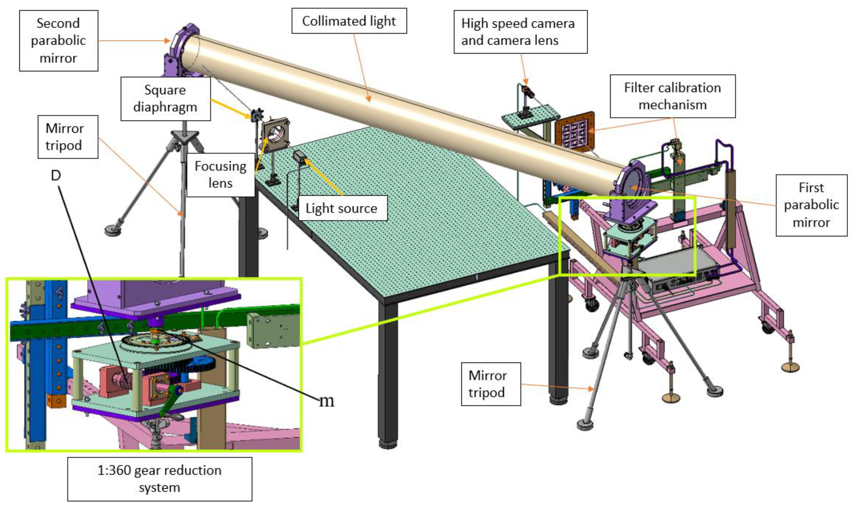
Figure 2 presents the integration of the proposed system into the Z-type schlieren system, after which the 1:360 reduction gear mechanism is presented in detail. This schlieren system also benefits from a color filter calibration mechanism described in [14].
A key advantage of the present design lies in its three-stage gear reduction layout and the enlarged engagement module between the worm and gear, which together significantly increase the load-bearing capacity of the system. Calculations indicate that the 1:360 reducer can transmit approximately twice the theoretical torque compared to equivalent assemblies constructed from separately purchased components. A short comparison of the proposed reduction mechanism vs. a commercially available components mechanism is presented in Table 2.
Table 2 presents a comparison between the conventional steel-bronze worm gear system and the 3D-printed resin alternative. Allowable pressure and torque values for hardened steel worms paired with phosphor bronze wheels are consistent with industry standards. For example, stress factors are tabulated at approximately 69 MPa bending strength and 8.3 MPa wear strength for sand-cast phosphor bronze wheels [15].
Table 3 represents the subassemblies and components included by them, which together make up the 1:360 gear reduction mechanism.
The invention is based on the use of three stages of speed reduction, manufactured from resin by means of 3D printing, with the parameters described in Table 4.
According to Table 4, the total gear reduction ratio is described by (7).
T 1 6 = T 1 2 · T 3 4 · T 5 6 = 1 30 · 1 3 · 1 4 = 1 360
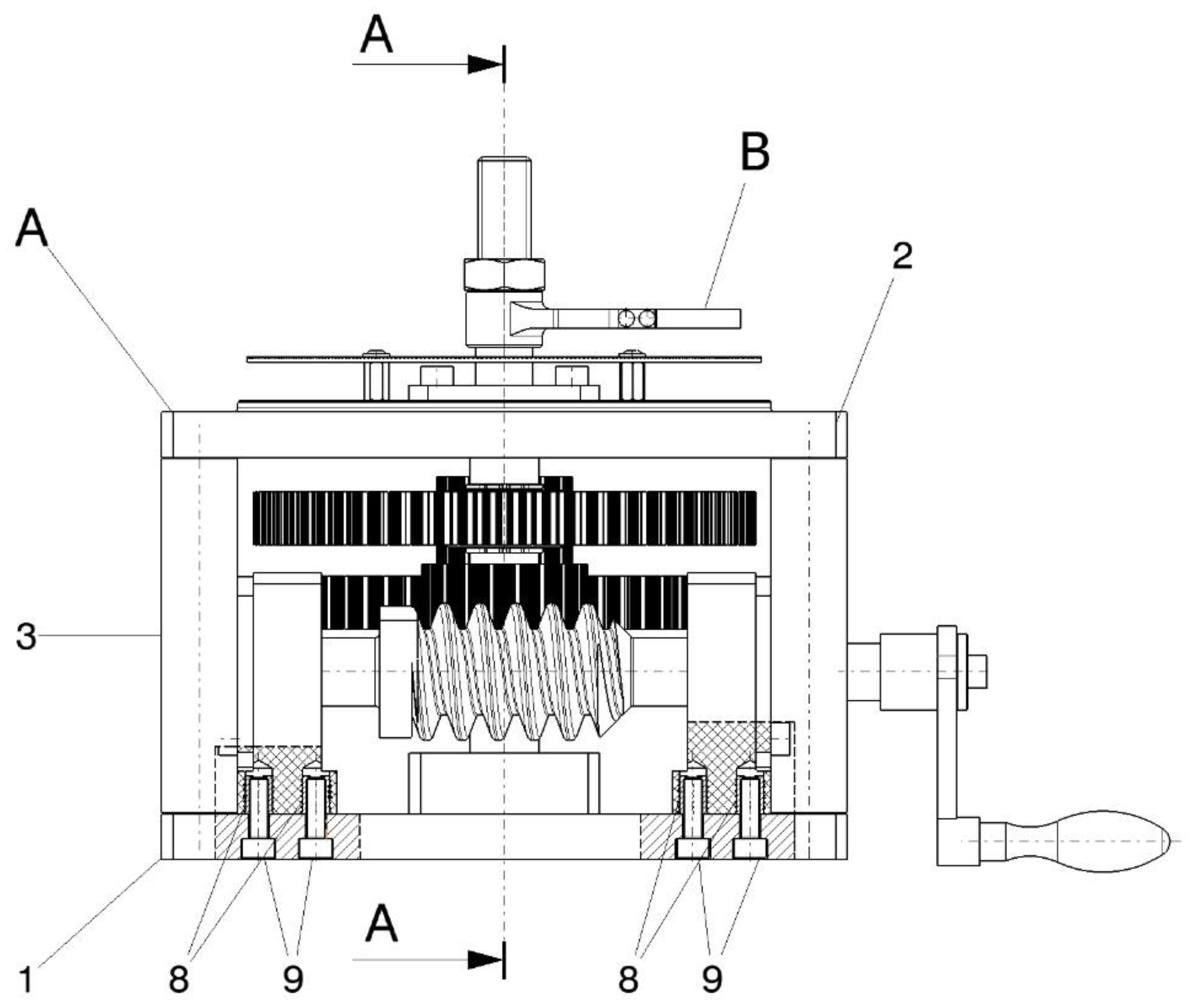
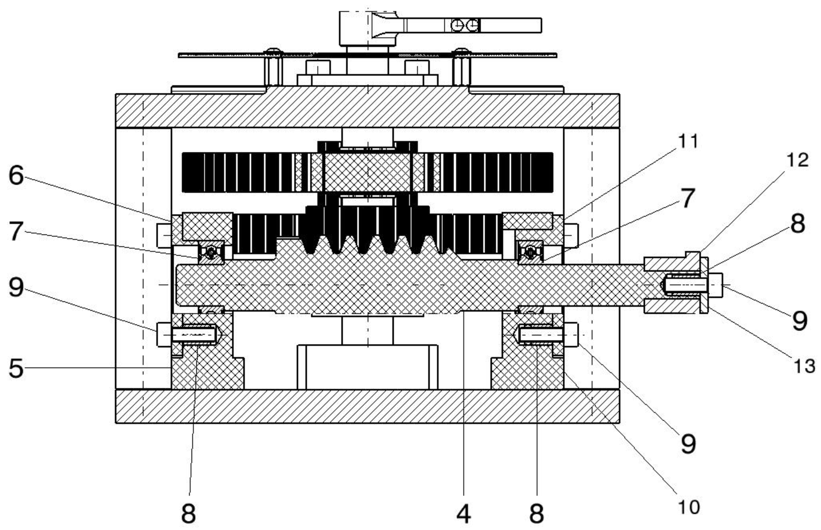
The main reduction stage T 1 2 is composed of a cylindrical worm with involute teeth (4) and a compound gear with 30 helical involute teeth and 20 straight involute teeth (14), which achieves the largest reduction ratio of the assembly, namely T 1 2 = 30 . The cylindrical worm with involute teeth (4) is driven by a standard lever with a square socket (12) [19], fixed to it by means of a washer (13) and a screw (9), which is fastened into the shaft of the standard lever with square socket (12) using a threaded metal insert (8). The cylindrical worm with involute teeth (4) is supported by two caged ball bearings (7), mounted in the bearing housings (5 and 10), secured with the bearing caps (6 and 11), which are fixed to the bearing housings (5 and 10) by screws (9) and threaded inserts (8). The bearing housings (5 and 10) are mounted on the lower plate (1) of anodized duralumin of the 1:360 reducer housing A, using screws (9) and threaded inserts (8), as shown in Figure 3.
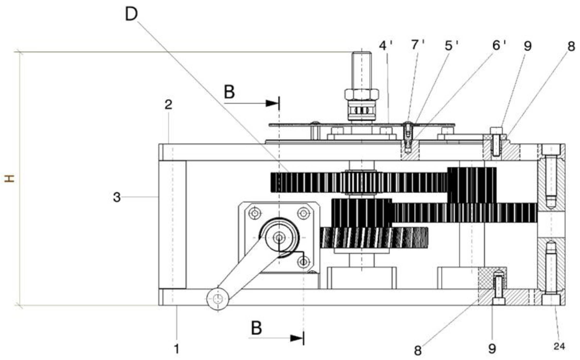
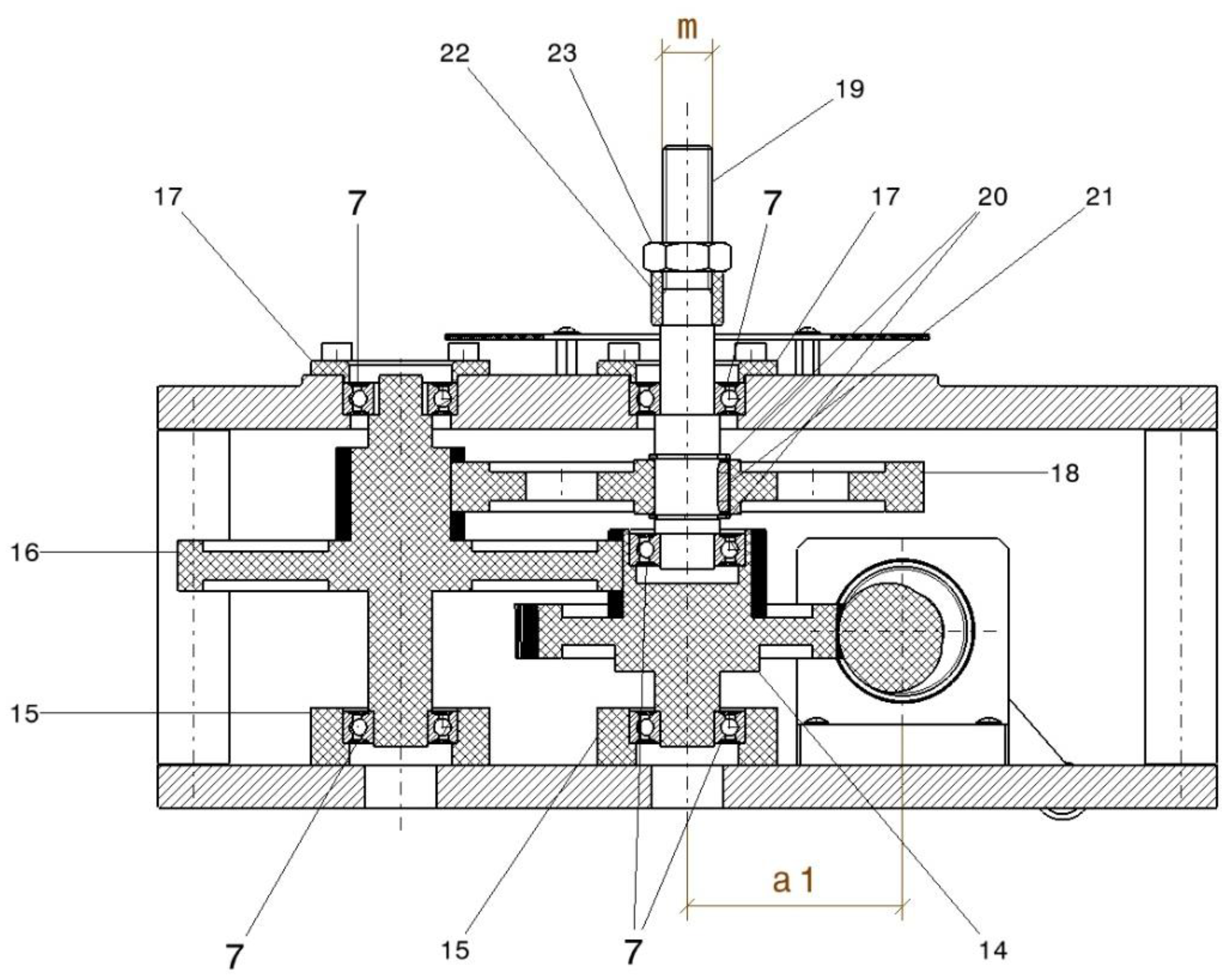
The housing subassembly A of the 1:360 reducer, in the form of an open frame, consists of metallic components, namely the lower plate (1), the upper plate (2) also made of anodized duralumin, separated by four stainless steel spacer cylinders (3), into which the fixing screws (24) are threaded. To the housing subassembly A, bearing housings (15) are also mounted on the lower plate (1), in which the caged ball bearings (7) are installed. These bearings support the compound gear with 30 helical involute teeth and 20 straight involute teeth (14) and the compound gear with 60 straight involute teeth and 16 straight involute teeth (16). In the upper plate (2), caged ball bearings (7) are installed and fixed by means of the bearing caps (17). These bearings support the shaft of the compound gear with 60 straight involute teeth and 16 straight involute teeth (16) and the metallic shaft (19), which is fixed at its lower end in the compound gear with 30 helical involute teeth and 20 straight involute teeth (14) by means of a caged ball bearing (7). To the metallic shaft (19) is attached the spur gear with involute straight teeth (18), by means of the parallel key (21) and the retaining rings (20). The bearing caps (17) are fixed to the upper plate (2) by screws (9) and threaded inserts (8), as illustrated by Figure 4.
Within the system, the position indicator subassembly B is also included (depicted in Figure 5), consisting of the indicator needle I, made from a lamella support (1′) and an indicator lamella (2′) attached by rivets (3′) to the lamella support (1′), and the circular indicator plate 0…360° (4′), which is attached to the upper plate (2) of the housing subassembly A by means of elevation nuts (5′), threaded metal inserts (6′), and screws (7′). The indicator needle I is attached to the metallic shaft (19) by means of nut (23). Coupling of the shaft with an external device is achieved through the thread at its end (m).
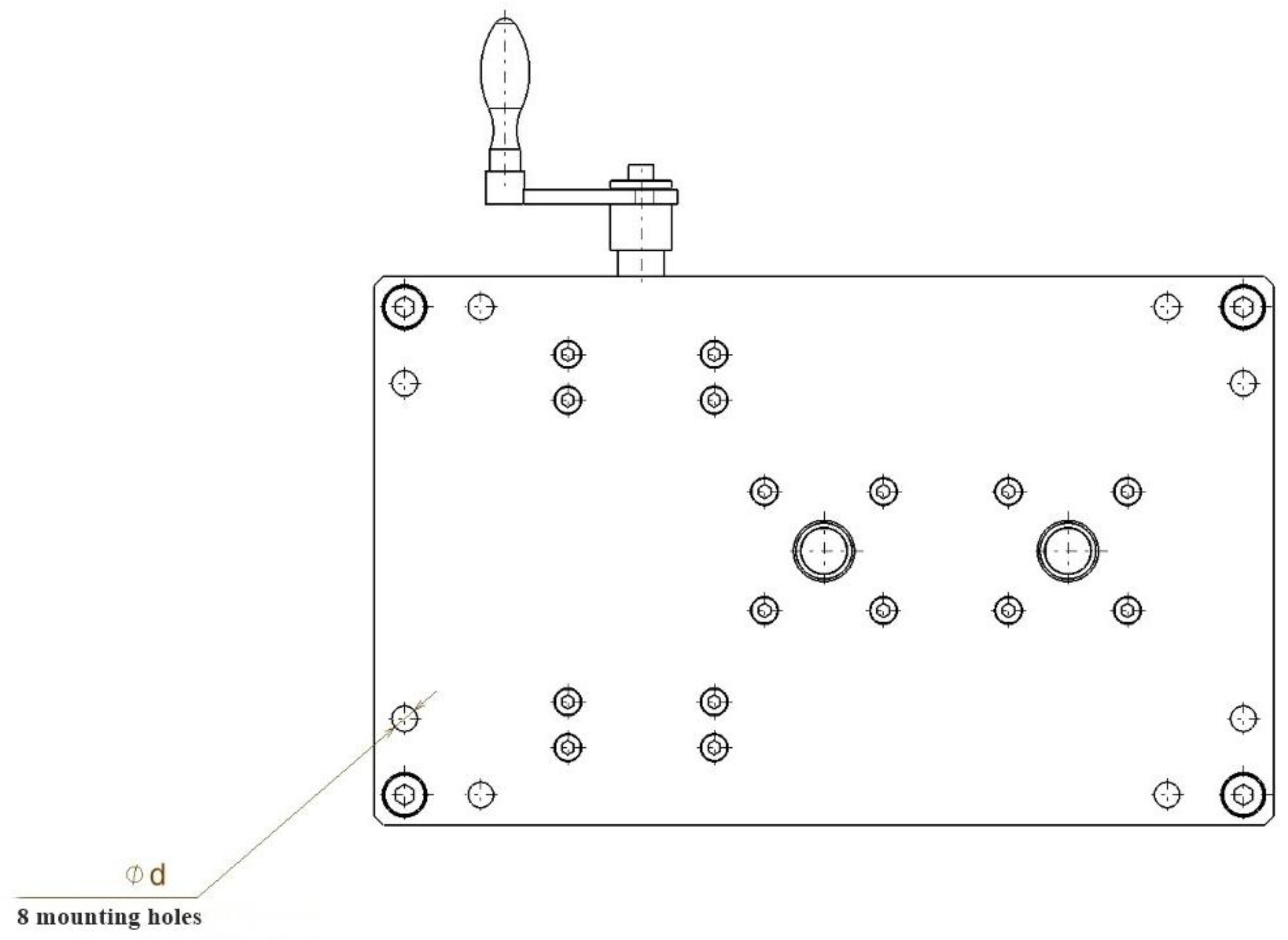
The overall dimensions of the assembly are L × l × H, the horizontal footprint L × l being approximately equal to the size of an A4 sheet (180 × 295 mm), with the height H variable depending on the coupling length of the shaft (19), with a minimum dimension of 185 mm. Since the 1:360 reducer D is scalable, the dimensions a1 and a2 can take any values according to gear standards, in this example being a1 = 60 mm and a2 = 80 mm. The coupling thread dimension m is also scalable, in the present invention being able to take values between M10 and M14. The fixing holes d can also take various values for screws ranging from M6 to M10.
The functioning of the system involves the rotation of the cylindrical worm with involute teeth (4), single start, module 3, by means of the standard lever with square socket (12). Through rotation, this worm drives the compound gear (14) with 30 teeth of module 3, on which there is another spur gear, module 2, with 20 teeth, which rotates at the same speed. This gear in turn drives another compound gear (16) with 60 spur teeth, module 2, and 16 spur teeth, module 2, on which there is another spur gear, module 2, with 16 teeth, which in turn drives another spur gear with 64 teeth, module 2. Thus, the total reduction ratio is T 1 6 = 360 , given by relation (7) above, the ratio being displayed by the position indicator subassembly B, consisting of the indicator needle I and the circular dial (0–360°) (4′), which allows the reading of the coupled device’s position with an accuracy of 1°.
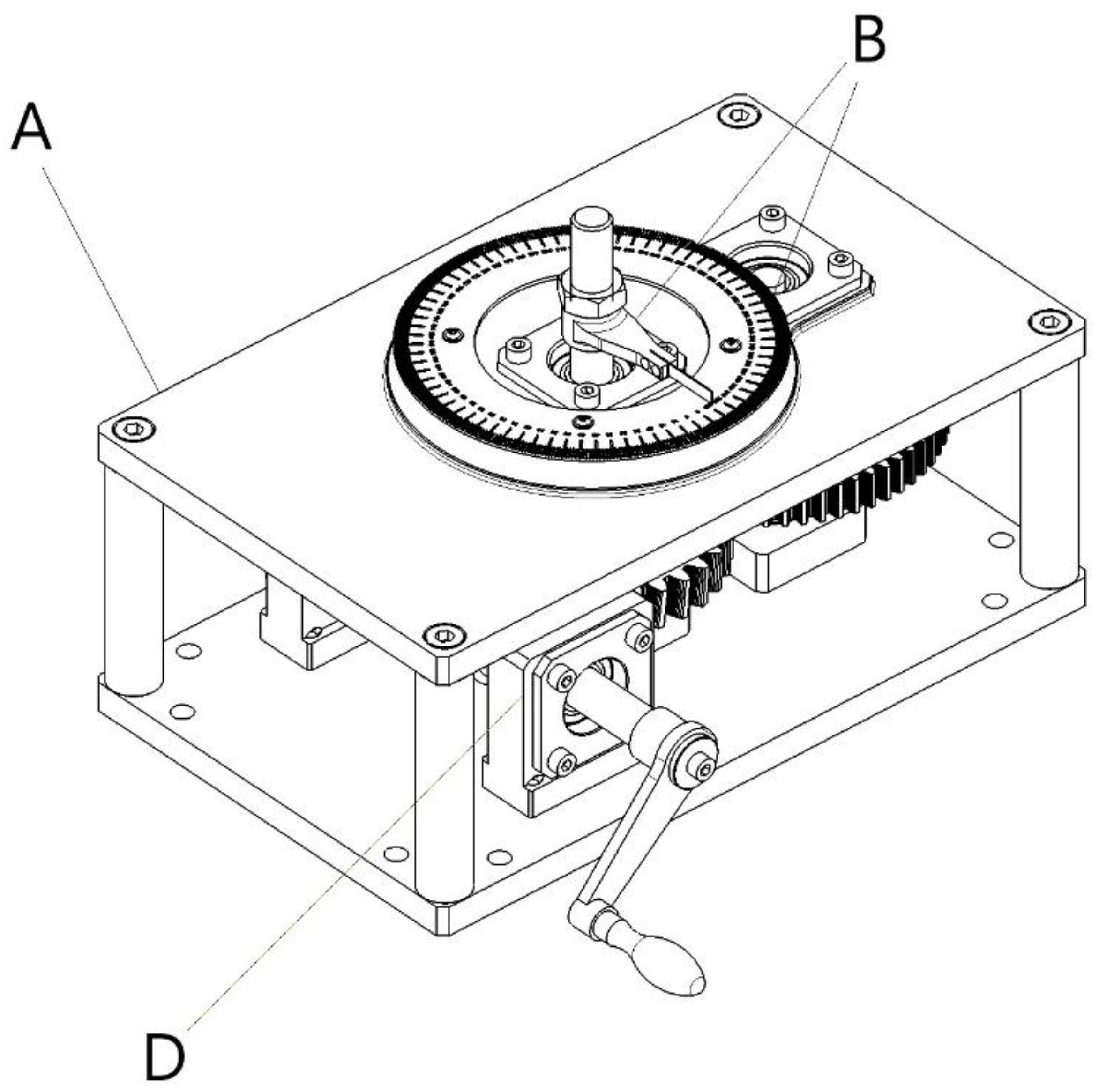
Figure 6 presents the isometric view of the proposed 1:360 gear reduction mechanism. Figure 7 represents the A-A section presented in Figure 3. Figure 8 illustrates the B-B section through the 1:360 gear reduction mechanism, and Figure 9 and Figure 10 illustrates the Top view, respectivelly Bottom view of the 1:360 gear reduction mechanism.

2.3. Additive Manufacturing Considerations Due to Design Constraints

The reduction gears were fabricated from Tough 2000 Resin [13] (Formlabs, Somerville, MA, USA [20]), selected for its high stiffness (tensile modulus ≈ 2 GPa), dimensional stability, and documented solvent compatibility. These properties are critical for preserving tooth geometry and ensuring precise meshing within the 1:360 gear train. Previous laboratory tests with Tough 2000 components, UV-cured and employed as parabolic mirror supports in a vacuum chamber, confirmed the feasibility of using this resin under vacuum conditions without evidence of outgassing or mechanical degradation. This observation is consistent with published studies showing that stereolithographic resins can be successfully employed in high-vacuum environments when properly post-cured [21], and with NASA outgassing data indicating that several Formlabs photopolymers exhibit acceptable TML and CVCM values under ASTM E595 testing [22].
Alternative photopolymers offered by Formlabs [20], such as Durable Resin [23] and Tough 1500 [24], were considered; however, their lower modulus and higher compliance render them less suitable for applications requiring minimal backlash and efficient torque transmission. Standard resins, although widely used for prototyping, were excluded due to their brittleness under load. The proposed components can be additively manufactured on a range of Formlabs printers, from Form 2 [25] to the more recent Form 4BL [26].
Beyond this setup, other materials and platforms may be employed depending on the mechanical and environmental requirements. Nylon-based powders (e.g., PA11 [27], PA12 [28]) processed via selective laser sintering (Formlabs Fuse 1+ [29], EOS P110 [30], HP Multi Jet Fusion [31]) provide excellent wear resistance and low surface friction, making them suitable for continuously engaged gear systems. Fiber-reinforced composites, such as carbon-fiber or glass-fiber filled nylons (Markforged, Waltham, MA, USA [32], Prusa, Prague, Czech Republic [33], Ultimaker, Utrecht, The Netherlands [34]), can deliver enhanced load-bearing capacity, though often at the expense of fine geometric fidelity. For high-performance or chemically aggressive environments, thermoplastics such as PEEK [35] or acetal (Delrin) [36] remain established benchmarks, typically produced via machining or industrial additive platforms.
The successful realization of the proposed reduction gear system through additive manufacturing requires careful consideration of part orientation, support placement, support sizing, layer height, and post-processing. Orientation plays a decisive role in minimizing defects: spur gears should be tilted by 20–30° relative to the horizontal and rotated such that no tooth flank is the primary downfacing surface, thereby distributing supports over non-critical areas and preventing excessive peel forces on a single ring of teeth. For compound gears (such as 30-tooth helical with 20-tooth spur; 60-tooth spur with 16-tooth spur), the orientation should prioritize the most highly loaded tooth set, which is kept upwards with supports directed to the hub, web, or non-mating features. Worm gears (single-start, m = 3) should be inclined at 30–40° to allow the helical thread to remain largely self-supporting while avoiding unsupported crest lines [37,38].
Equally important is the strategy for support placement. Functional surfaces such as active tooth flanks, bores, keyways, and bearing-locating faces must be avoided, since even minor defects compromise accuracy, noise, and load transfer. Supports are preferably attached to hub faces, webs, spokes, and non-mating rims, with restricted use in non-critical tooth root filets when unavoidable. For worms, supports should be placed at shaft ends or non-functional flats. A practical workflow involves using the printer’s auto-orientation tools followed by manual editing with blockers to protect critical features, while reinforcing hubs and webs until red downfacing warnings are resolved. If unavoidable, a sacrificial keeper ring (0.6–1.0 mm thick) can be modeled around gear teeth to receive supports, which can then be removed post-cure with minimal finishing.
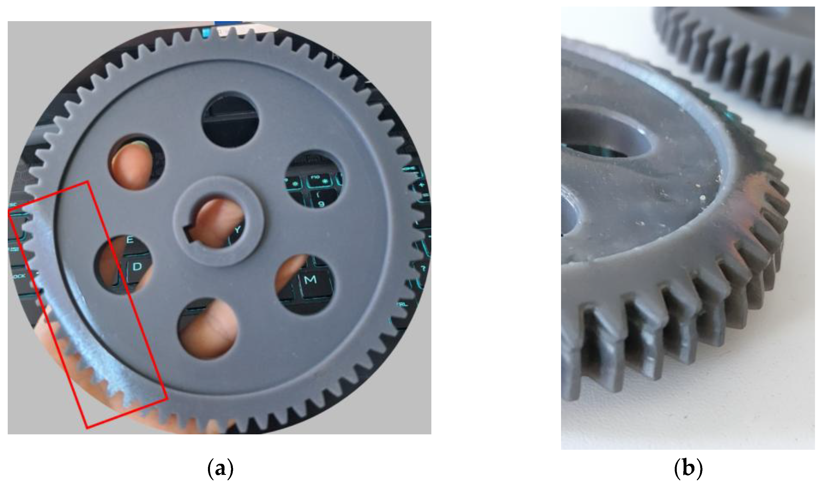
During experimental validation of the additive manufacturing recommendations, an initial gear prototype exhibited clear defects caused by suboptimal orientation and support distribution, as illustrated by Figure 11a,b. The most pronounced issue was the formation of a warped or shifted surface along the tooth profile (highlighted in Figure 10b), directly attributable to excessive peel forces concentrated in that area. This result underscores the importance of carefully distributing supports onto non-critical regions, as further discussed. A corrected build strategy, employing a 20–30° tilt and redistributed support placement, eliminated these issues in subsequent prints, yielding geometrically accurate gears, as it can be observed in Figure 11. These observations confirm the necessity of the recommended practices for ensuring both dimensional fidelity and functional performance of resin-based gear systems.
Support sizing must be adapted to part scale and resin properties. On the Form 3+ system [39], when printing with Tough 2000 resin [13], spur gears ≥40 mm diameter perform reliably with touchpoints of 0.50–0.60 mm at a support density of 0.6–0.8, combined with a Mini Raft (or Full Raft when fabricating multiple parts). Smaller gears (20–40 mm) benefit from finer supports (0.40–0.50 mm) at higher density (0.7–0.9), which distribute adhesion through multiple small contacts [40]. For elongated components such as worms, supports of ~0.60 mm are best applied near the ends and along the non-functional spine, with density ~0.6 to mitigate warping. Due to the stiffness of Tough 2000, undersized supports risk tearing during peel, making it safer to employ numerous small contacts rather than fewer, larger ones.
Finally, printing parameters and post-processing steps strongly influence dimensional accuracy. A layer height of 50 µm is recommended for gears to ensure fidelity of tooth geometry, whereas non-critical brackets may be fabricated at 100 µm. Shrinkage compensation should only be applied if experimentally calibrated, otherwise, default scaling is preferable, with post-machining of critical bores. All gears should be printed with a raft to avoid dimensional distortion from platform adhesion, and drain holes must be included in thicker webs or enclosed hubs to prevent cupping. Automatic warnings in the printer’s software should always be addressed prior to slicing [41]. Post-processing should follow resin-specific protocols: parts are rinsed in IPA with minimal agitation near teeth, cured exactly as specified in the Tough 2000 technical data sheet [13], and finished with only non-abrasive methods (e.g., hard plastic or fine fiber wheels) to preserve the involute profile of the teeth. Figure 12 shows the front view of the spur gear fabricated after applying the recommended orientation and support placement strategy. Unlike the initial defective print, the optimized gear exhibits uniform surface geometry and accurate tooth profiles, demonstrating the effectiveness of the proposed additive manufacturing guidelines.

3. Conclusions

This work has presented a novel 1:360 reduction gear system designed to enable precise angular positioning of optical components, with a primary application in the alignment of parabolic mirrors for schlieren diagnostics. The three-stage worm–gear assembly, fully manufactured by resin-based additive manufacturing on the Form 3+ system using Tough 2000, provides single-degree resolution in a compact, lightweight, and cost-efficient format. The inventive contribution extends beyond material substitution: unlike conventional bronze–steel reducers assembled from modular parts, the proposed design integrates a purpose-built architecture optimized for additive manufacturing, combining reduced weight, scalability, and adaptability for automated actuation.
Validation to date has been twofold. First, theoretical torque transmission and load-bearing capacity were derived from standard gear design equations, showing that the reducer achieves approximately twice the theoretical torque of equivalent modular systems. Second, practical feasibility was confirmed through the successful fabrication of gear prototypes, where defective and optimized prints (Figure 11 and Figure 12) demonstrated the necessity of the proposed additive manufacturing guidelines. Additional confidence is provided by manufacturer data on solvent compatibility and by laboratory tests in which Tough 2000 components were UV-cured and operated under vacuum without outgassing or degradation, consistent with published studies on SLA resins in high-vacuum environments. Together, these elements substantiate the claims of weight reduction, chemical resistance, and vacuum applicability.
Beyond the core mechanical design, the study consolidated best practices for additive manufacturing of functional gearing, including orientation strategies, support placement and sizing, layer height, and post-processing procedures. These recommendations ensure dimensional fidelity and reliability of the reducer and are transferable to other resin-based gear assemblies.
In conclusion, the proposed system demonstrates that additively manufactured polymer gear reducers can serve as robust, customizable alternatives to metallic counterparts, particularly in applications where low weight, modularity, chemical/vacuum compatibility, and rapid fabrication are priorities. This patent summary focuses on conceptual design and theoretical validation.
Future work will focus on comprehensive experimental validation of the proposed reducer. This will include torque transmission and backlash measurements, dimensional accuracy assessments, and long-term performance tests under variable environmental conditions such as vacuum and chemically aggressive atmospheres. Furthermore, integration into a working schlieren system is planned to directly evaluate optical alignment precision and sensitivity retention compared with conventional reducers. These efforts will provide a broader empirical foundation to complement the present design- and feasibility-oriented study and will help establish the scalability of resin-based gear systems for both research and industrial applications.

4. Patents

Patent application has been filled for the automated system at the Romanian State Office for Inventions and Trademarks, application number A0037/27.08.2025, titled: Manual 1:360 Reducer with Resin Gear Components.

Author Contributions

Conceptualization, E.G.P. and I.V.; methodology, I.V. and E.G.P.; software, I.V.; resources, E.G.P.; writing—original draft preparation, E.G.P.; writing—review and editing, I.V. and E.G.P.; All authors have read and agreed to the published version of the manuscript.

Funding

This work was carried out through the “Nucleu” Program, within the framework of the National Plan for Research, Development and Innovation 2023–2026, supported by the Romanian Ministry of Research, Innovation and Development, project number PN23.12.06.02.

Data Availability Statement

The original contributions presented in this study are included in the article. Further inquiries can be directed to the corresponding authors.

Acknowledgments

During the preparation of this manuscript, the author used ChatGPT 5.0 (OpenAI, https://chat.openai.com, accesed on25 September 2025) for language improvement. The authors have carefully reviewed, edited, and validated all outputs and assume full responsibility for the content of this publication.

Conflicts of Interest

The authors declare no conflicts of interest.

References

  1. Settles, G.S. Schlieren and Shadowgraph Techniques: Visualizing Phenomena in Transparent Media; Springer: Berlin, Germany, 2001; pp. 1–406. [Google Scholar]
  2. Zheng, L.; Susa, A.J.; Hanson, R.K. Methodology of designing compact schlieren systems using off-axis parabolic mirrors. Appl. Opt. 2022, 61, 4857–4864. [Google Scholar] [CrossRef] [PubMed]
  3. Speak, G.S.; Walters, D.J. Optical Considerations and Limitations of the Schlieren Method; Reports and Memoranda No. 2859; Aeronautical Research Council, Ministry of Supply: London, UK, January 1950. Available online: https://reports.aerade.cranfield.ac.uk/bitstream/handle/1826.2/3415/arc-rm-2859.pdf (accessed on 22 August 2025).
  4. Settles, G.S. Schlieren and shadowgraph techniques: Visualizing phenomena in transparent media. Flow Meas. Instrum. 1985, 1, 103–116. [Google Scholar] [CrossRef]
  5. Stevenson, D. Quantitative Colour Schlieren Techniques. Master’s Thesis, University of the Witwatersrand, Faculty of Engineering and the Built Environment, Johannesburg, South Africa, 2011. [Google Scholar]
  6. Caltech Course Handout. Schlieren Visualization (Ae104b, Winter 2014); Section “2.2 Schlieren”. Available online: https://shepherd.caltech.edu/T5/Ae104/Ae104b_handout2015.pdf (accessed on 21 August 2025).
  7. Mishra, S.S. Measurement of Gaussian Beam Width Using Knife Edge; National Institute of Science Education and Research (NISER): Bhubaneswar, India, 2013. [CrossRef]
  8. Siegman, A.E. Lasers; University Science Books: Sausalito, CA, USA, 1986; pp. 647–653. [Google Scholar]
  9. Born, M.; Wolf, E. Principles of Optics, 7th ed.; Cambridge University Press: Cambridge, UK, 1999. [Google Scholar]
  10. Smith, W.J. Modern Lens Design, 2nd ed.; McGraw–Hill: New York, NY, USA, 2005. [Google Scholar]
  11. 60:1 Gear Ratio, 360 Teeth, Worm Gear. Available online: https://www.govolition.com/product/V82-S1C86Z-P064B360S (accessed on 20 August 2025).
  12. Worms & Worm Gears. 64 Diametral Pitch. OndrivesUS.com. Available online: https://dpk3n3gg92jwt.cloudfront.net/domains/ondrives/pdf/gears-worm-wheel-WG64.pdf (accessed on 20 August 2025).
  13. Formlabs Inc. Tough 2000 Resin. Available online: https://formlabs.com/eu/store/materials/tough-2000-resin/?srsltid=AfmBOorN-ABIu9Q7P6jYOpulbmLPfL-BfZTVsnyRv1kal9AEN9TH13U0 (accessed on 20 August 2025).
  14. Prisăcariu, E.G.; Vlăducă, I. Automated Calibration Mechanism for Color Filter Integration in Quantitative Schlieren Systems with Rectangular Light Sources. Inventions 2025, 10, 53. [Google Scholar] [CrossRef]
  15. Spur Gears. Available online: https://deewanbittal.files.wordpress.com/2017/12/md-4_gear.pdf (accessed on 20 August 2025).
  16. Osakue, E.E.; Anetor, L. A Contact Stress Capacity Model for Cylindrical Wormsets. FME Transactions 2022, 50, 1–10. [Google Scholar] [CrossRef]
  17. RoyMech. Worm Gears. Available online: https://roymech.org/Useful_Tables/Drive/Worm_Gears.html (accessed on 20 August 2025).
  18. Framo Morat USA. Worm Gear Sets. Available online: https://us.framo-morat.com/products/worm-gear-sets (accessed on 20 August 2025).
  19. Elesa-Ganter. DIN 469. Crank Handles. Available online: https://catalog.monroeengineering.com/Asset/din-469.pdf (accessed on 20 August 2025).
  20. Formlabs Europe. Formlabs—High-Resolution SLA and SLS 3D Printers for Professionals. Available online: https://formlabs.com/eu/ (accessed on 21 August 2025).
  21. Radić, A.; Potočnik, B.; Maroh, M.; Poberaj, I. On the application of components manufactured with stereolithographic 3D printing in high vacuum systems. Vacuum 2024, 220, 112083. [Google Scholar] [CrossRef]
  22. NASA Outgassing Database. Materials Data for Additive-Manufactured Photopolymers. NASA GSFC. Available online: https://outgassing.nasa.gov/ (accessed on 21 September 2025).
  23. Formlabs. Durable Resin. Available online: https://formlabs.com/store/materials/durable-resin/?srsltid=AfmBOopA0rBX45GRITZJL8149vGiYKeTh3FZb9jTp52BWXmwjxM01Gec (accessed on 21 August 2025).
  24. Formlabs Inc. Tough 1500 Resin Technical Data Sheet (Rev. 01, 27 January 2020). Available online: https://formlabs-media.formlabs.com/datasheets/Tough_1500_TDS_EN.pdf (accessed on 21 August 2025).
  25. Formlabs. Form 2 Desktop Stereolithography (SLA) 3D Printer. Available online: https://formlabs.com/3d-printers/form-2/ (accessed on 21 August 2025).
  26. Formlabs. Form 4BL Large-Format 3D Printer—Medical/Dental SLA Platform. Available online: https://formlabs.com/3d-printers/form-4bl/ (accessed on 21 August 2025).
  27. 3D Systems. DuraForm PA11 Natural (SLS). Tough Nylon with High Elongation and Impact Resistance. Available online: https://www.3dsystems.com/materials/duraform-pa11-natural-sls (accessed on 21 August 2025).
  28. Materialise. PA 12 (SLS). Available online: https://www.materialise.com/en/industrial/3d-printing-materials/pa12-sls (accessed on 21 August 2025).
  29. Formlabs. Fuse 1+ 30W Compact SLS 3D Printer (Fuse Series). Available online: https://formlabs.com/eu/3d-printers/fuse-1/ (accessed on 21 August 2025).
  30. CDME, Ohio State University. EOS P110 Selective Laser Sintering (SLS) System. Available online: https://cdme.osu.edu/eos-p110, (accessed on 21 August 2025).
  31. HP. HP Multi Jet Fusion 3D Printing Technology. Available online: https://www.hp.com/us-en/printers/3d-printers/products/multi-jet-technology.html (accessed on 21 August 2025).
  32. Morgan, R.V.; McReynolds, B.; Husmann, K.; McCoy, J.; Maki, R.N.; Holguin, R.M.; Bernardin, J.D.; Siranosian, A.A. Markforged Continuous Fiber Composite Material Testing; Report Number LA-UR-20-25195; Los Alamos National Laboratory: Los Alamos, NM, USA, September 2020. Available online: https://www.osti.gov/servlets/purl/1641543/ (accessed on 25 September 2025).
  33. Prusa Research. Composite Materials. Original Prusa 3D Printers. Available online: https://www.prusa3d.com/category/composites/ (accessed on 21 August 2025).
  34. UltiMaker. Composite Materials for 3D Printing. Available online: https://ultimaker.com/materials/composite-materials-for-3d-printing/ (accessed on 21 August 2025).
  35. Ensinger Plastics. PEEK Plastic—TECAPEEK. Available online: https://www.ensingerplastics.com/en/thermoplastic-materials/peek-plastic (accessed on 21 August 2025).
  36. Kondo, H. POM (Acetal/Delrin) 3D Printing—All You Need to Know. All3DP. Updated 13 January 2024. Available online: https://all3dp.com/2/pom-acetal-delrin-3d-printing/ (accessed on 21 August 2025).
  37. Prusa Knowledge Base. Object Orientation. Available online: https://help.prusa3d.com/article/object-orientation_1658 (accessed on 21 August 2025).
  38. Formlabs Support. Model Orientation Best Practices for SLA Printing. Available online: https://support.formlabs.com/s/article/Model-Orientation?language=en_US (accessed on 21 August 2025).
  39. Formlabs. Form 3+ Desktop Resin 3D Printer—Industrial-Quality SLA Platform. Available online: https://formlabs.com/3d-printers/form-3/ (accessed on 22 August 2025).
  40. Formlabs Community Forum. PreForm Touchpoint Size. General Discussion. Jackson, 27 July 2021. Available online: https://forum.formlabs.com/t/preform-touchpoint-size/31580 (accessed on 22 August 2025).
  41. Formlabs Support. Automatic Layout Settings for SLA Printing. Available online: https://support.formlabs.com/s/article/Automatic-layout-settings-for-SLA-printing?language=en_US (accessed on 22 August 2025).
Figure 1. Schematics of a classic Z-type system with highlighted mirror tilt angle, α .
Inventions 10 00089 g001
Figure 2. Integration of the 1:360 gear reduction system into the schlieren system, mounted in the Z-type configuration. (D is the subassembly of Demultiplicator and m is the metric connection between demultiplicator and the sustaining plate of the mirror).
Inventions 10 00089 g002
Figure 3. Lateral view of the 1:360 gear reduction mechanism. (A is the subassembly of the cage of demultiplicator and B is the subassembly of the angle indicator).
Inventions 10 00089 g003
Figure 4. Main view of the 1:360 gear reduction mechanism. (B is the subassembly of the angle indicator and D is the subassembly of Demultiplicator).
Inventions 10 00089 g004
Figure 5. Position indicator of the 1:360 gear reduction mechanism. (B is the subassembly of the angle indicator).
Inventions 10 00089 g005
Figure 6. Isometric view of the 1:360 gear reduction mechanism. (A is the subassembly of the cage of demultiplicator, B is the subassembly of the angle indicator and D is the subassembly of Demultiplicator).
Inventions 10 00089 g006
Figure 7. Section A-A through the 1:360 gear reduction mechanism. (m is the metric connection between demultiplicator and the sustaining plate of the mirror).
Inventions 10 00089 g007
Figure 8. Section B-B through the 1:360 gear reduction mechanism.
Inventions 10 00089 g008
Figure 9. Top view of the 1:360 gear reduction mechanism. (B is the subassembly of the angle indicator).
Inventions 10 00089 g009
Figure 10. Bottom view of the 1:360 gear reduction mechanism.
Inventions 10 00089 g010
Figure 11. Defective prototype of the 3D-printed reduction gear. (a) Front view of the spur gear showing the defective region (highlighted in red), caused by improper orientation and support distribution during SLA printing. (b) Close-up of the affected tooth section, where the resin surface appears distorted and uneven, producing a non-horizontal profile that compromises tooth geometry and meshing accuracy.
Inventions 10 00089 g011
Figure 12. Front-view of the spur gear manufactured after optimizing printing parameters.
Inventions 10 00089 g012
Table 1. Summary of design optimization variables and objectives for the 1:360 reduction gear system.
VariableConsiderationFinal Design Choice
Gear moduleLarger modules increase stiffness in resinm = 2–3
Tooth count distributionDefines reduction ratio and load sharing1:30, 1:3, 1:4 stages
Worm geometryHelix angle and start number affect smoothness/loadSingle-start, m = 3
Resin stiffnessLimits torque capacity vs. metalsTough 2000 selected
Hub/web thicknessMust support orientation and reduce warpingIncreased thickness in hubs/webs
Table 2. Brief comparison between the 1:360 reduction gear mechanism and a mechanism formed out of commercially available components [15,16,17,18].
ParameterGear Set 1–Steel Worm + Bronze Globoid Gear
(Commercially Available)
Gear Set 2–Worm + Tough 2000 Resin Gear
(3D Printed System)
Module [mm]0.43.00
Base diameter (used) [mm]143.5089.75
Tooth width [mm]4.7615.00
Contact area [ m m 2 ]0.921.21
Allowable pressure [MPa]8010
Allowable tangential force [N]72212
Pitch radius [m]0.071750.044875
Estimated allowable torque [ N · m ] 5.2 9.5
Table 3. Component list of the proposed 1:360 gear reduction system, detailing the mechanical elements of the additively manufactured worm–gear assembly.
Component Name/TypeComponent nb.Notes
Base plate (anodized duralumin)1Lower structural plate of housing A
Top plate (anodized duralumin)2Upper structural plate of housing A
Spacer cylinders (stainless steel)3Four spacers between plates, fixed with screws 24
Cylindrical worm with involute teeth4Single start, module 3; main input driven by crank
Bearing housings (lower)5, 10, 15Support for ball bearings 7
Bearing caps (lower)6,11Fix bearings in housings 5, 10
Ball bearings (caged)7Support worm 4, compound gears 14, 16, and shaft 19
Threaded metal inserts8Used to fix screws in plates/housings
Screws (general fasteners)9, 24Used to fix housings, caps, and plates
Standard crank with square socket12Input lever for worm 4
Washer13Fixing washer for crank assembly
Compound gear (30 helical teeth + 20 spur teeth)14Driven by worm 4; shares shaft with spur gear z3 = 20
Compound gear (60 spur teeth + 16 spur teeth)16Driven by gear z3 = 20; shares shaft with spur gear z5 = 16
Bearing caps (upper)17Fix ball bearings in upper plate 2
Spur gear18Mounted on metallic shaft 19, via key 21 and retaining rings 20
Metallic shaft19Connects gears 14 and 18; output shaft with threaded coupling m
Retaining rings20Secure spur gear 18 on shaft 19
Parallel key21Connects spur gear 18 to shaft 19
Indicator needle assemblyI (1′, 2′, 3′)Lamella support 1′, indicator plate 2′, rivets 3′
Circular indicator dial (0–360°)4′Mounted on top plate 2 with nuts 5′
Elevation nuts5′Used to fix circular dial 4′
Threaded metal inserts (indicator system)6′For dial assembly
Screws (indicator system)7′For dial assembly
Nut for fixing indicator needle to shaft23Connects needle I to shaft 19
Table 4. Breakdown of the three-stage 1:360 gear reduction system, listing component types, module values, tooth counts, compound gear relationships, and individual stage reduction ratios.
StageComponentsModule [mm]TeethNotesReduction Ratio
T1-2Cylindrical worm, type ZE [5], single start3 z 1 = 1 Engages with helical gear i 1 2 = 1 / 30
Helical gear,
α = 6 °
3 z 2 = 30 Part   of   compound   gear   with   z 3 i 3 4 = 1 / 3
T3-4Spur gear2 z 3 = 20 Shares shaft with z 2 = 30 ; forms compound gear
Spur gear2 z 4 = 60 Part of compound gear with z 5
T5-6Spur gear2 z 5 = 16 Shares shaft with z 4 = 60 ; forms compound gear i 5 6 = 1 / 4
Spur gear2 z 6 = 64 Output gear
Disclaimer/Publisher’s Note: The statements, opinions and data contained in all publications are solely those of the individual author(s) and contributor(s) and not of MDPI and/or the editor(s). MDPI and/or the editor(s) disclaim responsibility for any injury to people or property resulting from any ideas, methods, instructions or products referred to in the content.