1. Introduction
Thermochemical energy storage (TCES) represents a critical solution for managing fluctuating renewable energy sources by storing energy in the form of chemical reactions. This energy can be released when needed by reversing the chemical reactions, making it an ideal system for balancing energy demand and supply. One of the most challenging aspects of designing and optimizing TCES systems is understanding the heat and mass transfer processes that occur within the storage media, which can significantly affect the overall system performance. As such, computational simulations have emerged as powerful tools for studying these intricate processes, providing a detailed understanding of how different parameters influence heat transfer, mass transport, and energy efficiency.
Simulation of heat and mass transfer in TCES plays a crucial role in enhancing the understanding of complex thermal and fluid flow processes. This is particularly vital in thermochemical reactions where energy storage occurs through endothermic and exothermic reactions. In this context, computational fluid dynamics (CFD) and other numerical modeling techniques offer detailed insights into the mechanisms driving these processes, helping engineers optimize design parameters for better efficiency, reliability, and scalability of TCES systems [
1,
2,
3]. In TCES systems, energy is stored during an endothermic chemical reaction and is released during an exothermic reverse reaction. This process involves a solid or liquid reactant that undergoes physical and chemical changes under varying thermal conditions. Materials such as calcium oxide (CaO), magnesium oxide (MgO), and metal hydrides are commonly used due to their high energy densities and thermal stability [
4,
5]. Heat and mass transfer play a significant role in determining the reaction kinetics, storage efficiency, and thermal performance of these systems. Heat transfer in TCES primarily involves conduction, convection, and sometimes radiation, depending on the type of reactor and operating conditions. Mass transfer, on the other hand, deals with the transport of reactants and products in gaseous or solid states, which can be influenced by diffusion and advection processes. The complexity of these mechanisms often requires sophisticated simulation approaches to predict performance under different operating scenarios [
6,
7,
8].
CFD has become an indispensable tool for simulating heat and mass transfer in TCES systems. By solving the Navier–Stokes equations along with energy and species transport equations, CFD allows for the prediction of temperature profiles, fluid velocities, pressure distributions, and concentration gradients within the storage medium [
9]. For example, CFD simulations can be used to model heat transfer in packed bed reactors, which are commonly employed in TCES systems due to their high surface area for heat exchange. These models help in optimizing the geometry, material properties, and operating conditions to maximize energy storage and retrieval [
10]. Furthermore, CFD has been used to investigate the impact of reaction kinetics on heat and mass transfer, especially in systems that involve metal oxides and metal hydrides. For instance, CFD models can simulate the adsorption and desorption processes in metal hydride-based storage systems, where hydrogen absorption or release involves heat generation or consumption, thus affecting the overall heat transfer performance [
11]. The interaction between mass transport and heat release in these reactions is highly complex and often requires multi-physics simulations that couple thermal and chemical processes [
12,
13].
In addition to CFD, multi-scale modeling approaches are being employed to simulate heat and mass transfer in TCES systems. These approaches bridge the gap between micro-scale phenomena, such as diffusion within porous materials, and macro-scale system behavior. For instance, pore-scale models can capture the transport of gas molecules within porous thermochemical materials, while system-level models focus on the overall energy storage and retrieval performance [
14]. Combining these scales allows for a more comprehensive understanding of how microstructural properties of materials affect the macroscopic performance of TCES systems [
15]. Multi-physics simulations, on the other hand, integrate various physical phenomena such as heat transfer, mass transport, and chemical kinetics into a single computational framework. This is particularly important in TCES systems, where the heat generated or absorbed during chemical reactions directly influences mass transport. For example, in metal oxide-based TCES, the oxidation and reduction reactions are accompanied by significant heat transfer, which needs to be modeled accurately to optimize reactor design [
16,
17]. Multi-physics models help in predicting the temperature gradients, concentration profiles, and reaction rates more accurately than single-physics models [
18].
Several studies have demonstrated the use of simulations for optimizing TCES systems. In one study, CFD was used to model the heat transfer in a calcium oxide-based storage system, where the endothermic decomposition of calcium carbonate (CaCO3) into calcium oxide and CO
2 was simulated under different temperature conditions [
19]. The study found that optimizing the reactor geometry and material properties could significantly enhance heat transfer and reaction rates, leading to improved storage efficiency. Another case study focused on metal hydride-based TCES, where a multi-physics simulation was employed to model the hydrogen absorption and release processes [
20]. The simulation revealed that controlling the heat transfer rate during the absorption phase was crucial for preventing overheating and ensuring efficient hydrogen storage. By adjusting the thermal conductivity of the storage material and the reactor design, the system’s overall performance was significantly improved [
21]. Additionally, pore-scale simulations have been used to study the diffusion of reactants within porous thermochemical materials. These models help in understanding how the microstructural properties of materials, such as pore size and distribution, affect mass transport and heat transfer [
7]. By optimizing the porosity and surface area of the storage material, researchers have been able to enhance the overall energy density and efficiency of TCES systems.
The future of simulation in TCES lies in the integration of machine learning with traditional CFD and multi-physics models. Machine learning algorithms can be used to analyze large datasets generated from simulations and experiments, identifying patterns and trends that can inform future designs. For example, machine learning can be applied to optimize the selection of thermochemical materials by predicting their performance under different operating conditions based on historical data [
22]. Similarly, machine learning can be used to develop surrogate models that reduce the computational cost of multi-scale simulations, allowing for faster optimization of system parameters [
23]. Although CFD has been extensively used to model heat and mass transfer in energy systems, many studies fail to account for the dynamic coupling between thermal and chemical reactions over time, especially under real-world operating conditions [
3,
5]. Moreover, while several studies have focused on metal oxides or metal hydrides as storage media, comprehensive research on alternative materials like SrCl
2—especially in combination with expanded graphite (EG)—is limited [
7,
8]. The detailed analysis of how different compression ratios (CR) and heat transfer fluid (HTF) flow rates affect system efficiency remains understudied, particularly with regard to minimizing sensible heat losses while maximizing desorption rates.
Additionally, previous works on TCES systems often emphasize small-scale laboratory experiments or focus primarily on theoretical models without sufficient validation through simulations under varied environmental conditions [
6,
9]. The scalability of these systems for integration with large-scale solar energy applications has also received limited attention, further limiting the practical implementation of these technologies [
12]. Furthermore, the majority of existing research has yet to provide a detailed analysis of how system performance can be optimized for both energy storage and cooling applications in the same framework [
23]. Innovative designs, such as integrated receiver–storage systems in concentrating solar thermal plants, offer potential solutions but primarily focus on thermal energy storage without addressing dual-use scenarios. To achieve practical scalability and multifunctionality, future research must bridge these gaps by integrating advanced simulation techniques, hybrid system designs, and real-world testing under diverse operational conditions.
Considering the heat input required for TCES systems, low-grade heat from renewable sources, such as solar, can be effectively supplied by solar-energy conversion technologies, such as photovoltaic-thermal (PVT) [
24]. Looking at the potential of solar energy in electricity generation in Southeast Asian countries, Vietnam led the region with solar power accounting for approximately 11% of its electricity generation mix, showcasing rapid growth in recent years [
25]. Thailand, another regional leader, had about 4% of its electricity generated from solar sources [
26]. In contrast, countries like Indonesia and Malaysia have seen slower adoption, with solar contributing less than 1% to their electricity production [
27]. The Philippines has made progress, with solar reaching around 1.7% of its electricity mix [
28]. Singapore, despite its limited land area, has set ambitious targets and achieved about 1.5% solar share in its electricity generation [
29]. These figures underscore the varying stages of solar energy adoption across Southeast Asia, with some countries making significant strides while others are still in the early phases of solar integration.
The growing adoption of solar energy in Southeast Asia and other regions aligns well with the potential for integrating TCES systems with solar-energy conversion technologies leading to a greener solution in the energy sector. PVT systems simultaneously generate electricity and capture thermal energy, making them an efficient and sustainable source of heat for driving endothermic reactions in TCES [
30]. Studies have shown that PVT systems can deliver consistent low-grade heat within the optimal temperature range required for various thermochemical reactions, such as those involving calcium chloride (CaCl
2) and strontium chloride (SrCl
2), enhancing the overall efficiency and sustainability of energy storage systems [
31]. The integration of PVT technologies with TCES not only maximizes the utilization of solar energy but also minimizes the reliance on conventional heating methods, making it a viable solution for large-scale renewable energy applications. Furthermore, the heat and mass transfer dynamics in such integrated systems have been extensively studied using computational simulations, providing valuable insights for optimizing system performance under varied environmental conditions.
Given these gaps, the importance of this research lies in its simulation-driven optimization of SrCl2-based systems, which offers a new pathway for improving the reliability and efficiency of thermochemical energy storage. This study addresses the critical challenge of maximizing energy storage capacity by optimizing the CR, a factor that has not been adequately explored in the literature. Furthermore, this research underscores the potential for SrCl2-based TCES to offer more sustainable and efficient solutions for renewable energy storage, aligning with global energy goals for reducing fossil fuel dependence and enhancing the capacity of renewable technologies. It highlights how advanced simulations can bridge the gap between theoretical models and practical applications, leading to better system design and operation in real-world scenarios. Thus, this research is a key contribution to advancing renewable energy storage technologies, paving the way for future innovations in TCES systems.
2. Methodology
This section outlines the steps and methods used to develop a high-efficiency heat and mass exchanger for an adsorption cooling cycle. The methodology is based on findings from previous research, which resulted in the creation of a novel composite material consisting of metal salts and porous carbon. This material demonstrates excellent heat and mass transfer properties, making it an ideal candidate for the design of an efficient heat exchanger. The research methodology encompasses several key stages, including theoretical performance analysis, heat exchanger design, engineering simulations, and prototype development and testing, all aimed at achieving the project’s objectives. The calculation of the appropriate material quantity is critical in designing a heat exchanger that meets the required size and performance specifications. Data obtained from the energy release efficiency analysis were used to calculate the mass and volume of the composite material necessary for the heat exchanger. This calculation takes into account the specific energy (energy per unit mass) of the composite material, the energy density (energy per unit volume), and the required energy release rate for various cooling applications.
By accurately determining the material requirements based on these parameters, the design process ensures that the heat exchanger can deliver optimal performance in terms of energy transfer and cooling capacity. Sorption models presented in Equation (1) for the desorption process and Equation (2) for the adsorption process are from Mazet, Amouroux, and Spinner [
32], where
Ar is the Arrhenius term,
x is the degree of conversion,
t is time,
m is the reaction pseudo-order,
is the thermodynamic equilibrium pressure in Pascal, which is a function of the reactant temperature (
), and
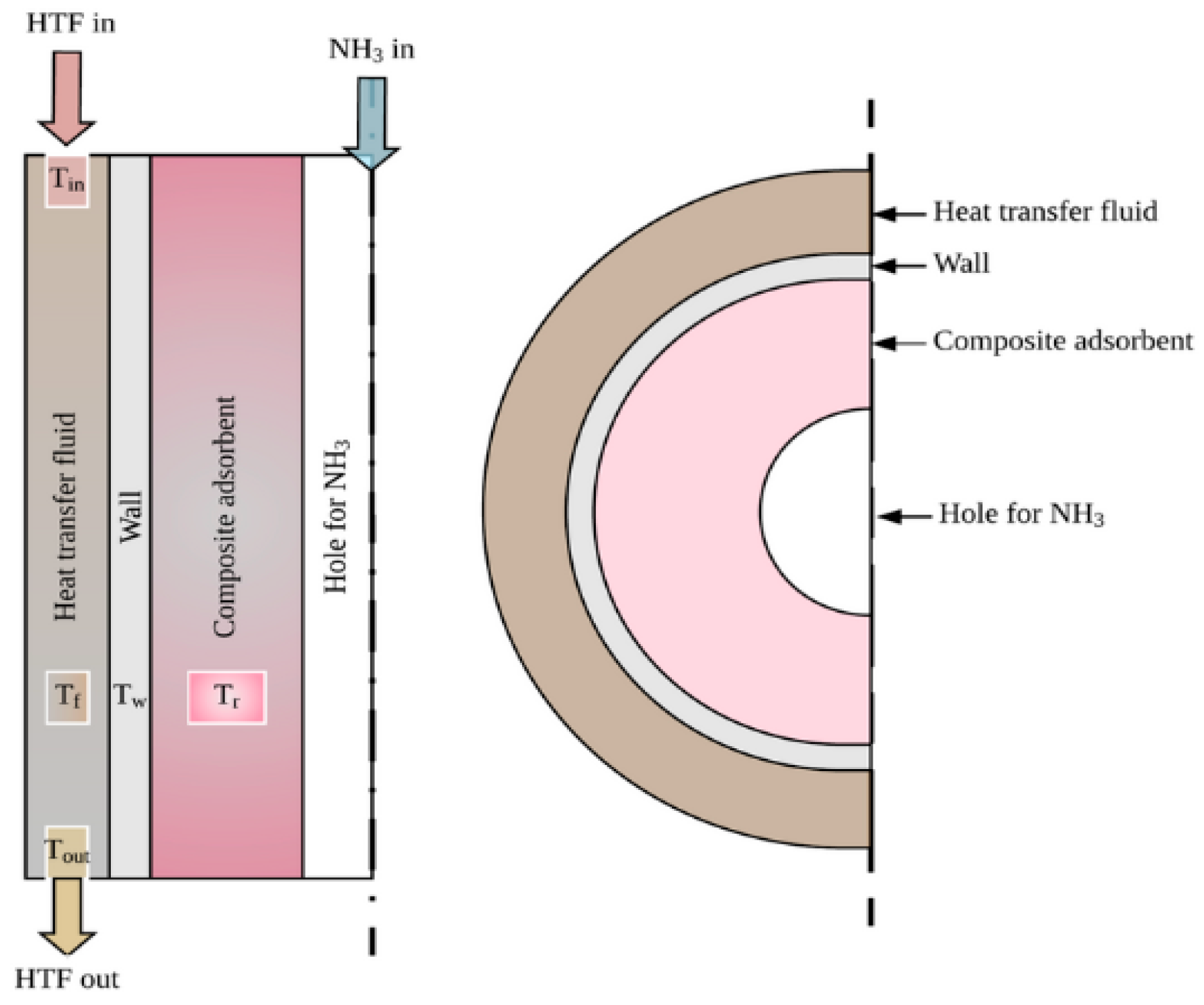
is the pressure in the reactor dominated by the condenser/evaporator in Pascal. The calculations also consider the application-specific cooling demands, which play a crucial role in determining the overall dimensions and material usage in the heat exchanger. This approach ensures that the design is both efficient and scalable for practical thermochemical energy storage and cooling systems. In the initial phase of the research, a heat exchanger model called Simple Reactor Layers (Water Jacket) was studied, as shown in
Figure 1. This heat exchanger structure consists of multiple layers, including a composite absorbent layer specifically designed to absorb ammonia (NH
3) during the heat transfer process. The primary function of the composite absorbent is to capture the substance for heat exchange. The flow of the HTF begins by entering the heat exchange channel and passing through the composite absorbent layer before exiting at the other end. This well-designed structure enhances the efficiency of heat transfer between the internal fluids and the liquid passing through the external water jacket.
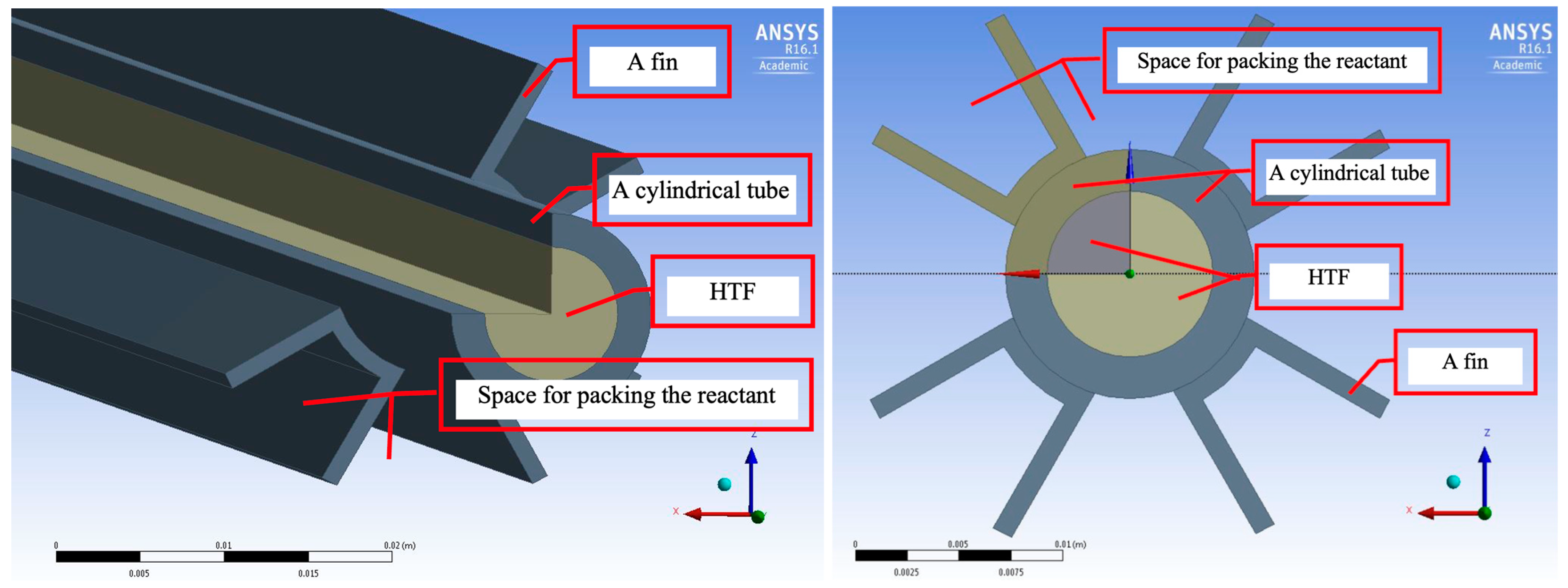
In this process, water (or another coolant) serves as the medium for absorbing and transferring heat through the water jacket. The water jacket acts as a barrier, ensuring that the heat generated from the internal process is effectively transferred to the external environment. This structure significantly reduces heat loss during the process and leads to more efficient energy transfer. Additionally, it helps in lowering operational energy costs by optimizing the heat exchange process. This configuration of the heat exchanger, particularly its layered design with a composite absorbent, is crucial for improving the performance of systems utilizing thermochemical sorption for both energy storage and cooling applications. In the subsequent design phase, the structure of the fin-tube reactor, as shown in
Figure 2, was studied. This design focuses on the use of fins to increase the surface area available for heat exchange. The fins attached to the tubes serve to enhance the rate of heat transfer from the HTF to the material contained within the tubes. By increasing the surface area, the fins facilitate faster and more efficient heat exchange with the surrounding air or liquid.
The inclusion of fins in the reactor design significantly improves the efficiency of heat transfer by enabling a larger surface area for interaction between the reactor and its environment. This leads to improved thermal performance, making the heat exchanger more effective in both cooling and energy storage applications. In this configuration, the fin-tube design offers an advantage by accelerating heat dissipation, making it well-suited for systems requiring rapid and efficient heat transfer. The study of the fin-tube reactor structure demonstrates a design advantage that enhances heat transfer by adding fins to expand the surface area. This increased surface area helps to improve the rate of heat transfer from the HTF to the external environment. This design approach is one of the methods that can be adapted for the new composite materials developed in this year’s research.
Both structures studied and compared in this research highlight the potential of using composite materials in more efficient heat exchangers. These composite materials exhibit superior heat absorption capabilities and can further enhance heat transfer rates when used with the fin-tube design. Additionally, the flexibility of this design allows for adjustments to suit various applications. From the study and analysis of both heat exchanger structures, it is evident that integrating the newly developed composite materials into these systems is likely to significantly improve heat exchange efficiency. Future design and testing efforts will further enable the application of these composite materials, developed this year, in diverse energy and industrial processes.
Performance analysis using ANSYS Fluent R16.1 was conducted by importing the three-dimensional (3D) model into ANSYS Fluent software for simulation and evaluation, with model coefficients shown in
Table 1. The model was checked for completeness, and material properties for the composite and other components were defined. Appropriate boundary conditions and simulation parameters were set, including inlet and outlet temperatures and pressures, flow rates of the working fluid, and the thermal and mass properties of the composite material. The simulation was then performed using ANSYS to analyze temperature distribution within the heat exchanger, the flow of the working fluid, and mass transfer, as well as heat loss and overall system efficiency. This process allowed for an assessment of the heat and mass transfer performance, identifying potential issues such as heat accumulation or uneven flow, and comparing the results to the predefined specifications.
3. Model Validation
This section presents the findings and analysis of the energy absorption system’s performance, focusing on the comparison between simulation results and experimental data from related studies. The primary objective of this study was to evaluate the efficiency of the energy absorption and heat transfer system to gather insights that can be utilized for optimizing the design and enhancing real-world applications. These findings offer a deeper understanding of the factors that impact the system’s performance and provide guidance for future design improvements.
In this research, SrCl2 was selected as the energy storage salt due to its high efficiency in absorbing and transferring thermal energy, making it suitable for use in the thermochemical sorption system developed for both short-term and long-term energy storage. SrCl2 offers a significant cost advantage compared to other salts like BaBr2, which, although more efficient, is considerably more expensive. By selecting SrCl2, the development costs of the energy storage system are reduced without compromising operational efficiency. Moreover, SrCl2 exhibits stability and longevity, allowing it to be used for extended periods without frequent material replacement, thus reducing long-term operational expenses. All of these factors support the decision to utilize SrCl2 in this energy storage system.
SrCl2 demonstrates excellent thermal energy absorption capabilities, with a reaction enthalpy that is well-suited for energy storage in a thermochemical sorption system. Its ability to operate across a wide range of temperatures makes it an ideal candidate for efficient heat transfer and energy storage applications. During the validation of the adsorption and desorption models for the energy storage system, several key parameters were employed to compare the simulation results with experimental data. One of the critical parameters was the mass of SrCl2 used in each tube, which was 0.18 kg, with a salt-to-EG mass ratio of 2:1. The amount of EG used in the process was 0.09 kg, and when combined, the composite adsorbent had a density of 250 kg per cubic meter. This combination illustrates the system’s ability to store and transfer energy efficiently.
Additionally, the density of pure SrCl
2, which plays a vital role in the energy absorption process, was determined to be 3052 kg per cubic meter. These parameters were used in the simulation to assess how closely the adsorption and desorption models aligned with the actual experimental results. The analysis using sorption models from Mazet, Amouroux, and Spinner [
32] underscored the importance of setting accurate parameters to properly evaluate and validate the energy storage system, particularly when comparing the simulation results to experimental data under real-world conditions. By establishing and analyzing these parameters, this study ensured that the simulated models closely reflected actual system performance, providing reliable insights for optimizing the design and enhancing the overall efficiency of thermochemical energy storage systems.
From the graph in
Figure 3, a comparison between the adsorption results from the simulation and the experimental results of [
33] is presented, along with the percentage deviation. The left axis shows the global conversion of the adsorption system, comparing the experimental data with the simulation results, while the right axis displays the percentage deviation (% deviation) between the two sets of results. From the data in the graph, it can be observed that, at the beginning of the reaction, the deviation is quite high, exceeding 60% in the first 10 min (0.1 h). The primary reason for this high deviation is the low global conversion during the initial stages of the process, which results in a relatively high percentage deviation, even though the overall trend of the simulation closely matches the experimental results.
However, as time progressed, the deviation clearly decreased, falling below 10% after one hour and eventually reaching approximately 1.3% when the global conversion reached around 0.86. This indicates that the simulation and experimental results aligned more closely during the later stages of adsorption. The values of Ar = 0.009, m = 3.06, and E0 = 1421 shown in the graph represent the parameters used in the simulation, reflecting the system’s adsorption characteristics. The graph also shows that the simulation closely matched the experimental results throughout most of the reaction, except for the high deviation observed at the start.
In
Figure 4, the comparison between the simulation and experimental results during the desorption process, under temperature conditions of 100–20 °C, is displayed. Both data sets show global conversion on the left axis and deviation on the right axis. The global conversion starts at around 1 and gradually decreases over time. The simulation and experimental results closely align throughout the process, particularly during the latter stages when the data sets are in strong agreement. During the early stages of the process (0 to approximately 0.2 h), the deviation fluctuates significantly, peaking at about 20%. Afterward, the deviation decreases to below 10% and remains consistently under 20% for the remainder of the process, with a slight increase toward the end of the experiment. The parameters used in the simulation, such as
Ar, m, and
E0, were fine-tuned for this test, demonstrating that the simulation accurately predicted the experimental results with a satisfactory level of precision.
4. Results
In
Figure 5, the temperature response in various parts of the reactor system and the global conversion values are shown during the initial stages of the process. The system started operating at 20:56, with the initial temperature of the HTF in the reactor being 90 °C. The global conversion began at approximately 0.95 and gradually decreased over time as the system progressed. The graph illustrates temperatures at different points within the system, such as the preset temperature at the reactor outlet, which remained stable at around 5 °C after the system began operating. Additionally, the temperature of the salt equilibrium was compared, and it remained at the same level as the preset temperature. In the early phase, the temperature at the reactor outlet dropped rapidly from the initial 90 °C before stabilizing gradually. The global conversion also declined steadily as the temperature at the reactor outlet decreased, but this reduction occurred slowly and progressively, indicating continuous energy loss within the system. This graph highlights the operation of the reactor system under conditions where SrCl
2-EG was used, with a temperature drop to 5 °C at equilibrium and an initial reactor temperature of 90 °C.
In
Figure 6, the flow of the HTF and the average temperature at the reactor outlet during summer conditions, using SrCl
2, are shown. The parameters are set as follows: dT_drop = 5 °C, T_in = 90 °C, and CR = 12. The left axis of the graph represents the HTF flow rate in kilograms per second (kg/s), while the right axis shows the temperature in degrees Celsius (°C). The graph indicates that the system operation began at 21:00, during which time the HTF remained stationary (HTF stationary period). Continuous HTF flow started after 21:05. The average outlet temperature of the HTF (shown by the red line) dropped rapidly from its initial temperature of around 90 °C, eventually stabilizing at approximately 30 °C. Meanwhile, the equilibrium temperature of the salt (represented by the purple line) remained constant at around 30 °C throughout the process. The HTF stationary period lasted from 21:00 to approximately 21:05, after which the HTF began to flow. This flow led to a rapid decrease in temperature, as observed in the graph. The graph illustrates the relationship between the HTF flow and the temperature change at the reactor outlet, where the HTF flow significantly affected the reduction of temperature within the system.
In
Figure 7, the relationship between system pressure and global conversion using SrCl
2 under summer conditions is depicted. The parameters are set with dT_drop = 5°C, T_in = 90°C, and CR = 12. The left axis of the graph shows the pressure in Pascals (Pa), while the right axis shows the global conversion. At the start of the process, at 21:00, the system begins operating with the salt pressure (red line) rapidly rising to a peak of around 135 kPa before slowly decreasing. This continuous decline in pressure during the system’s operation reflects the equilibrium adjustment of the salt. Meanwhile, the reactor pressure (blue line) remains constant at around 50 kPa throughout the process.
The global conversion starts at approximately 0.95 and gradually decreases to around 0.85 by 21:14. The reduction in global conversion corresponds with the pressure drop within the system, indicating energy loss. The graph also displays dP_drop, which represents the pressure difference between the salt and the reactor. This pressure drop directly influences the change in global conversion as the system operates. In
Figure 8, the relationship between salt equilibrium pressure (P_eq) and reactor pressure (P_c), along with global conversion, is illustrated. The system starts at 21:00 under the condition of using SrCl
2-EG, with an equilibrium temperature of 5 °C and an initial reactor temperature of 90 °C, with CR = 1. At the beginning of the process, the salt equilibrium pressure (red line) rapidly increases to approximately 700 kPa, which is higher than the reactor pressure (blue line), remaining steady at around 500 kPa. This pressure difference, represented as dP_drop, is a critical factor that initiates the desorption process, as the salt pressure exceeds the reactor pressure. As the process continues, the salt equilibrium pressure begins to decrease, and global conversion gradually falls from around 1.00 to approximately 0.85. Meanwhile, the reactor pressure remains constant, indicating a stable desorption process once the system enters a phase with a clear pressure difference.
In
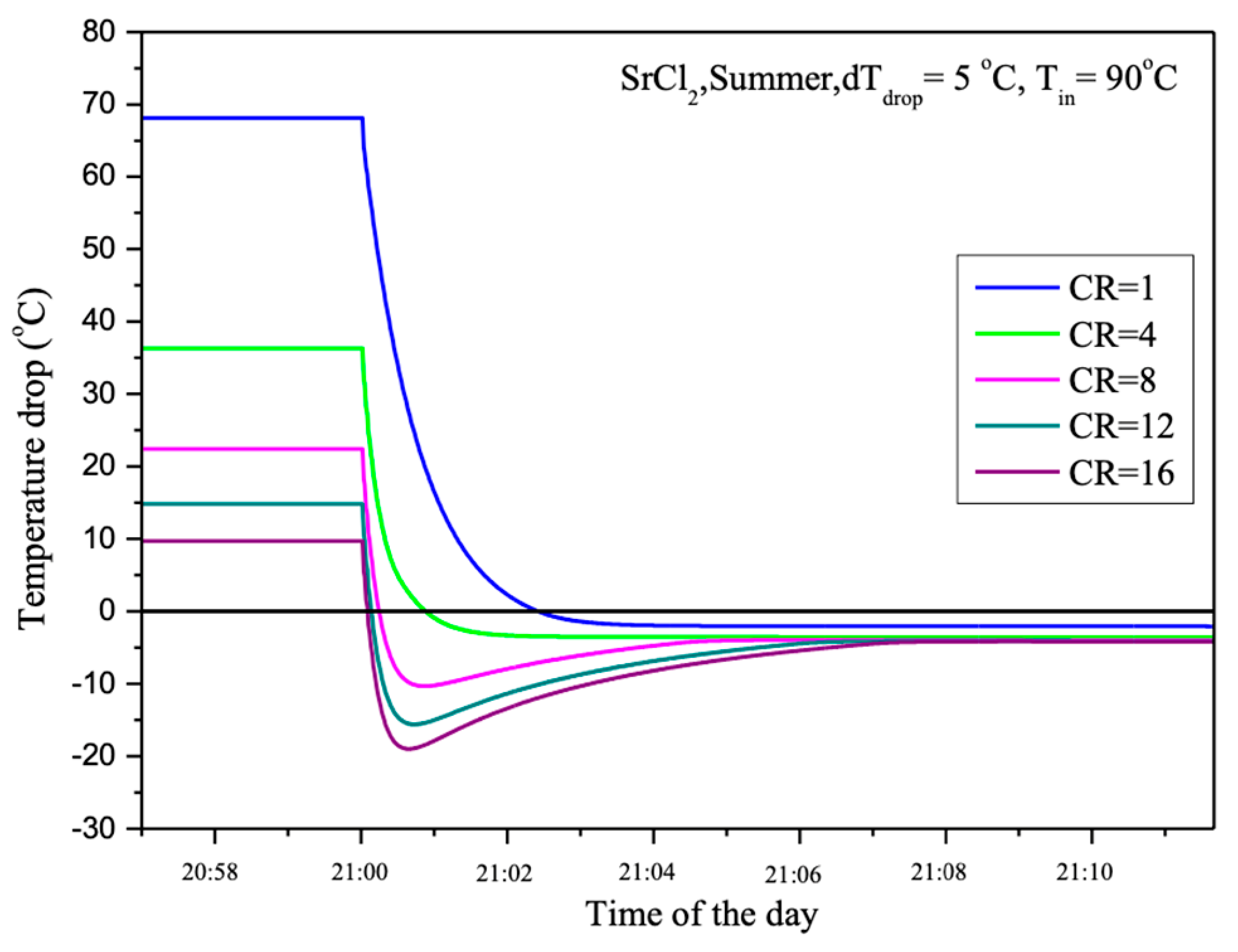
Figure 9, the changes in temperature drop in relation to different CR are illustrated under operating conditions of dT_drop = 5 °C and T_in = 90 °C. The vertical axis represents the temperature drop in degrees Celsius, while the horizontal axis indicates the time of day. The graph shows that the temperature drop begins rapidly after the system starts. The varying CR values affect the magnitude of the temperature drop. A higher CR results in a greater temperature drop during the early stage of the process. When CR = 1, the maximum temperature drop reaches approximately 70 °C, while at CR = 16, the maximum temperature drop is around 20 °C.
After the initial rapid temperature drop, the temperature gradually returns to equilibrium in all cases. The larger initial temperature drops recover more quickly, but the temperature recovery trend for each CR remains similar. Higher CR values show a slightly slower recovery rate compared to lower CR values. This graph highlights the importance of CR in influencing temperature changes within the system, suggesting that the system can be optimized for different applications based on these conditions.
To maintain the 5 °C temperature difference (dT_drop) between the outlet HTF temperature and the equilibrium temperature (T_eq), the HTF flow rate was adjusted as shown in
Figure 10. At CR = 1, the non-equilibrium reactant temperature needs to be maintained at 84.75 °C, causing a rapid increase in the HTF flow rate, as indicated by the blue line. As a result, with limited HTF production from the PV/T panels, the energy storage system without compressor assistance (CR = 1) can hardly store the thermal energy generated from the PV/T system in the thermochemical sorption energy storage (TSES) system.
When compressor assistance is applied (CR > 1), the HTF flow rate significantly decreases. For instance, at CR = 4, the maximum HTF flow rate drops from 18 × 10
−4 to around 2.5 × 10
−4 kilograms per second, as the reactant temperature can be maintained at 54.36 °C to preserve the non-equilibrium state for the desorption process. With higher CR, a lower reactant temperature can be used to sustain the desorption process, allowing more thermal energy from the PV/T production to be utilized.
Figure 10 also shows that using higher CR lowers the reactant temperature, providing the additional benefit of reducing sensible heat and allowing more thermal energy to be used in the desorption process rather than being lost as unstorable thermal mass. From the results displayed in the graph, it is evident that the energy storage system operating at CR = 16 can store up to 94% of the thermal energy produced by the PV/T system, compared to just 78% at CR = 1. The remaining thermal energy is consumed as sensible heat, assuming no energy loss to the environment.
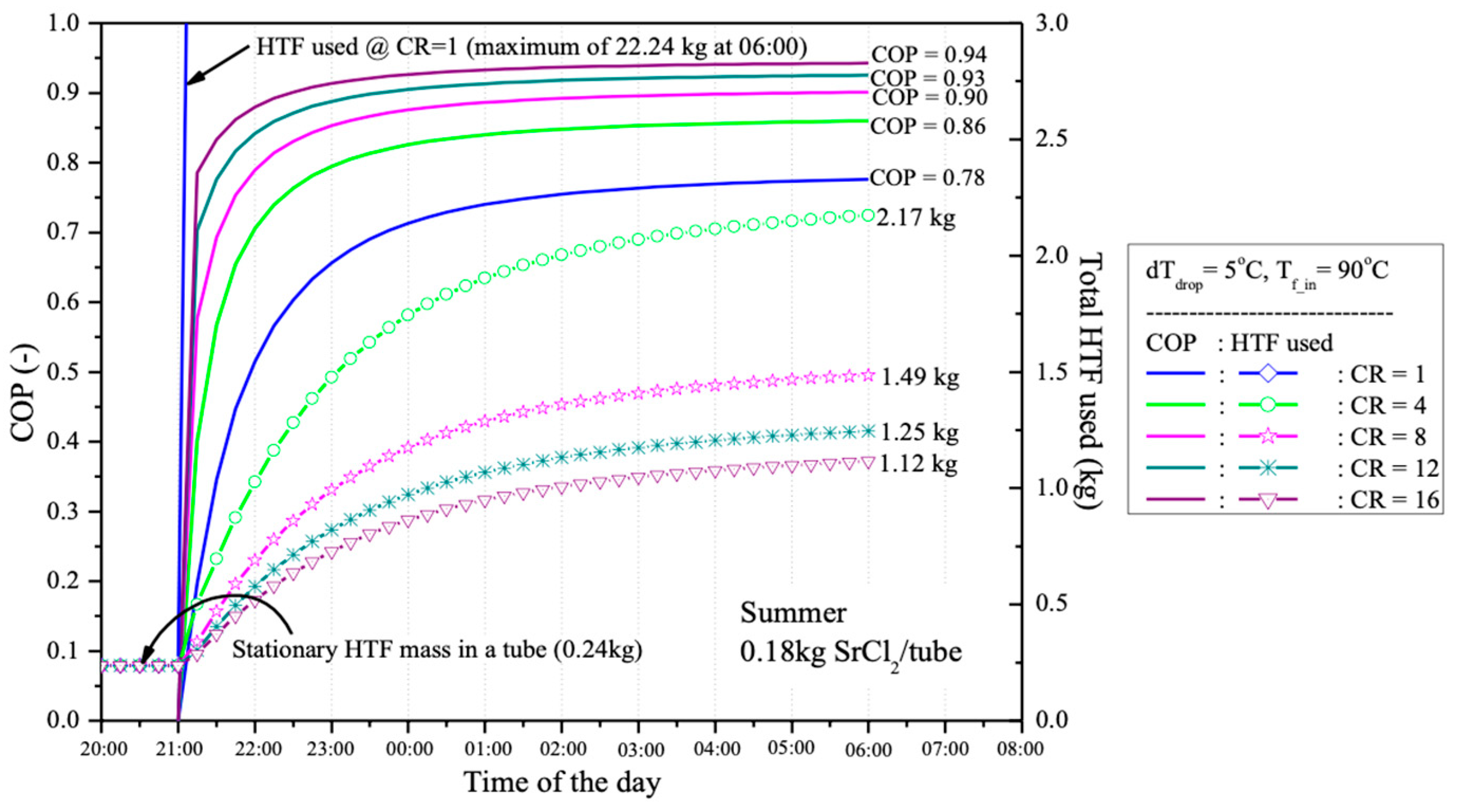
The percentage of heat used in the desorption process is employed to indicate the coefficient of performance (COP) of the desorption system when different CR values are applied, as shown in
Figure 11. Due to the higher COP and the larger temperature difference between HTF and TR when higher CR is used, the amount of HTF required for desorption is presented in
Figure 11 for a single reactant tube containing 0.18 kg of SrCl
2, with a salt-to-EG ratio of 3:1. At CR = 1, 22.24 kg of HTF at 90 °C are required to maintain the non-equilibrium desorption process for 9 h, from 21:00 to 06:00 the following day. However, with CR = 4, the required amount of HTF at 90 °C is reduced to just 2.17 kg, which is nearly 10 times less than the amount needed without compressor assistance (CR = 1).
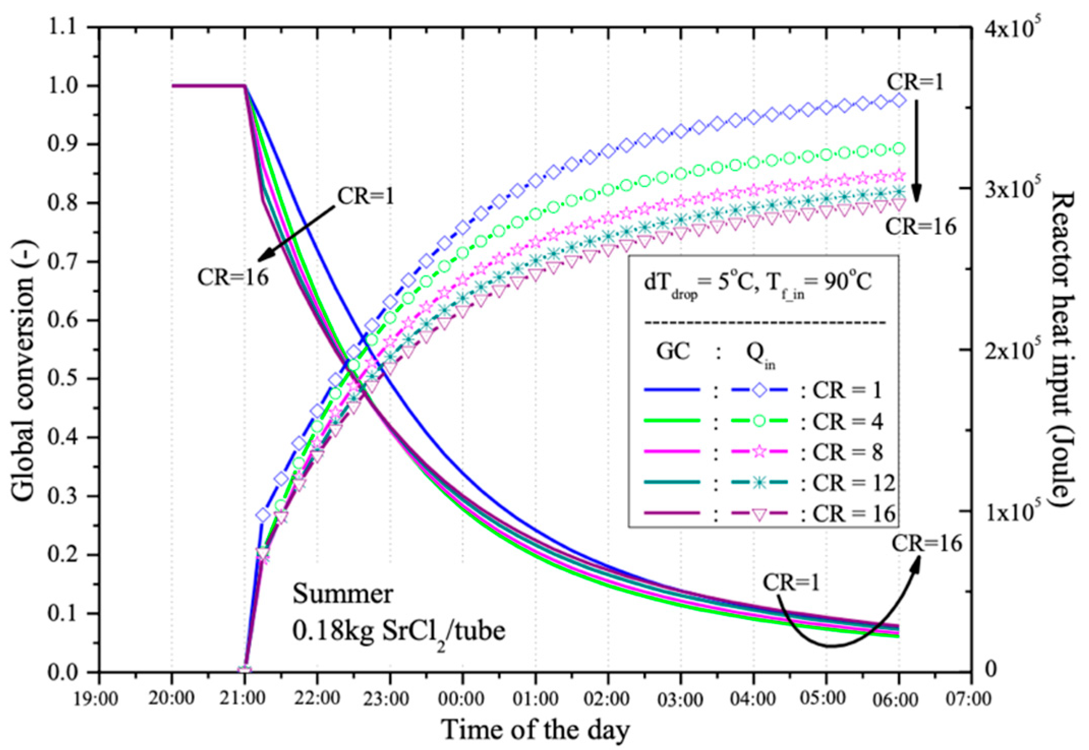
After a 9-h desorption process, from 21:00 (after sunset when the HTF is produced by the PV/T panel) until 06:00 the next day (before the HTF is reused in the PV/T panel), the global conversion of the reactant (0.18 kg of SrCl
2 in a water-jacketed reactant tube) is presented in
Figure 11. It is observed that with different CR values, the reactant can be desorbed by more than 90% after 9 h. The best performance occurs at CR = 4, with a desorption rate of 93.8%, followed by 93.3%, 92.6%, 92.6%, and 92.1% at CR = 8, 12, 1, and 16, respectively. The thermal energy used for each global conversion at different CR values is also shown in
Figure 12. It is evident that when a lower CR is used, more thermal energy is required compared to cases with higher CR. This is because, with a higher CR, the operating temperature of the reactant decreases, reducing the required sensible heat. Therefore, using a higher CR tends to provide higher energy storage efficiency.
These results underscore the effectiveness of the SrCl2-based thermochemical energy storage system developed in this study. The high conversion rates, efficient pressure management, and significantly reduced HTF flow rates at higher compression ratios indicate that this system performs at or above the standards set by similar technologies in the field. The ability to achieve such high efficiency with lower HTF flow rates, particularly at higher compression ratios, suggests that this system could offer substantial improvements in energy storage density and overall system performance compared to existing standards in thermochemical energy storage.
5. Conclusions and Discussion
This research focuses on the development of a TSES system, utilizing SrCl2 combined with EG as a material capable of absorbing and releasing heat. The goal is to enhance the efficiency of thermal energy storage from Photovoltaic/Thermal (PV/T) solar panels. This study evaluates the desorption and adsorption processes using various parameters, such as different CR, adjustments to the HTF temperature, and reactant temperature control. Both experimental results and simulations were analyzed to show the relationships between these variables and the performance of the energy storage system.
The experiments employed various CR values, including CR = 1, 4, 8, 12, and 16, to assess their effects on desorption and adsorption processes. This research found that CR plays a crucial role in system performance. As CR increases, the reactant temperature decreases, which raises the amount of thermal energy used in the desorption process. On the other hand, with a lower CR (such as CR = 1), the reactant temperature is higher, requiring a higher HTF flow rate to reduce the system temperature and maintain equilibrium. This results in lower efficiency in storing thermal energy from the PV/T system. The simulation and experimental results show that at CR = 1, 22.24 kg of the HTF is required during the 9-h desorption process, a significantly high amount compared to CR = 4, which requires only 2.17 kg. This reduction in HTF usage indicates increased system efficiency with the aid of a compressor at higher CR values.
This research found that with higher CR values, the system can store more thermal energy. Calculations of the percentage of heat used in the desorption process reveal that at CR = 16, the system can store up to 94% of the thermal energy produced by the PV/T system, compared to only 78% at CR = 1. This is because higher CR values reduce sensible heat, allowing more energy to be used in the desorption process instead of being lost as unstorable heat. The analysis of global conversion values during the desorption process after 9 h (from 21:00 to 06:00 the following day) shows that the system can desorb over 90% of the reactant at all CR levels. The highest performance occurred at CR = 4, where 93.8% desorption was achieved, followed by CR = 8 (93.3%), CR = 12 (92.6%), CR = 1 (92.6%), and CR = 16 (92.1%). These findings suggest that higher CR values result in more efficient desorption, as more thermal energy is directly utilized in the process, with less being lost as sensible heat.
In addition to short-term experiments focusing on desorption and adsorption, this research also conducted long-term evaluations to assess the system’s ability to store energy over extended periods. Continuous operations, such as energy storage from PV/T panels during the day and energy release during the night, were examined. The results indicate that systems with higher CR values, such as CR = 4 and CR = 8, can maintain consistent performance and energy storage without significant energy loss to desorption or sensible heat, compared to lower CR values. The experiments demonstrate that systems with higher CR values can operate more efficiently over the long term, as the daily HTF usage decreases with increasing CR values, allowing the system to store more thermal energy while consuming less operational energy.
Based on these research findings, it can be concluded that higher CR values significantly impact the efficiency of TSES systems. Systems using higher CR values, such as CR = 4 and CR = 8, exhibit greater energy storage efficiency and require less HTF for operation. Recommendations for future system development include studying the optimization of reactant temperature settings and designing systems that further minimize energy losses due to sensible heat. The implementation of precise HTF flow control technology to improve energy efficiency is another potential area for future development. Additionally, exploring alternative materials beyond SrCl2 with higher energy storage efficiency may offer new possibilities for adapting the system to different operational conditions.


 ,
, 


