
Improving the Thermal Efficiency of Gasket Plate Heat Exchangers Used in Vegetable Oil Processing


Abstract
1. Introduction
2. Materials and Methods/Research Method
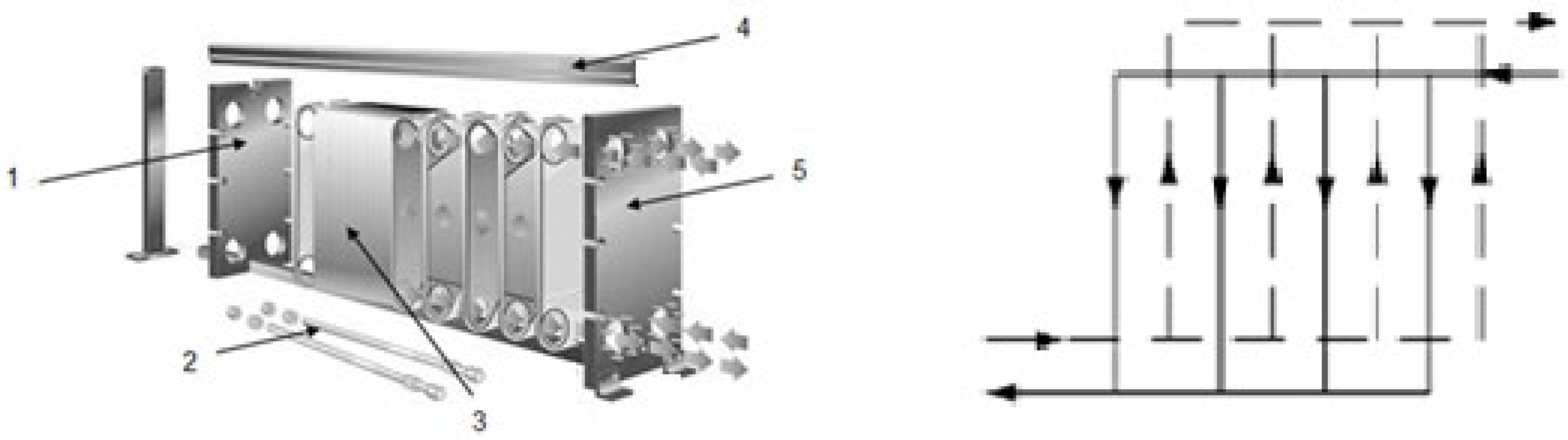
2.1. Equipment
2.2. The Research Design
2.2.1. The Base Case
2.2.2. The Change in Corrugation Angles, Cooling Fluid, and Plate Material
3. Model
- -
- dh,sine is the hydraulic diameter of the sine duct, calculated with Equation (2) being related to the independent variable x—the ratio corrugation depth: corrugation wavelength (x = b/l), in Equation (2):
- -
- fapp is the apparent friction factor, which takes into account the flow through sine duct. fapp is calculated with Equation (3):
4. Results and Discussion
4.1. Changing the Chevron Angle of Plates
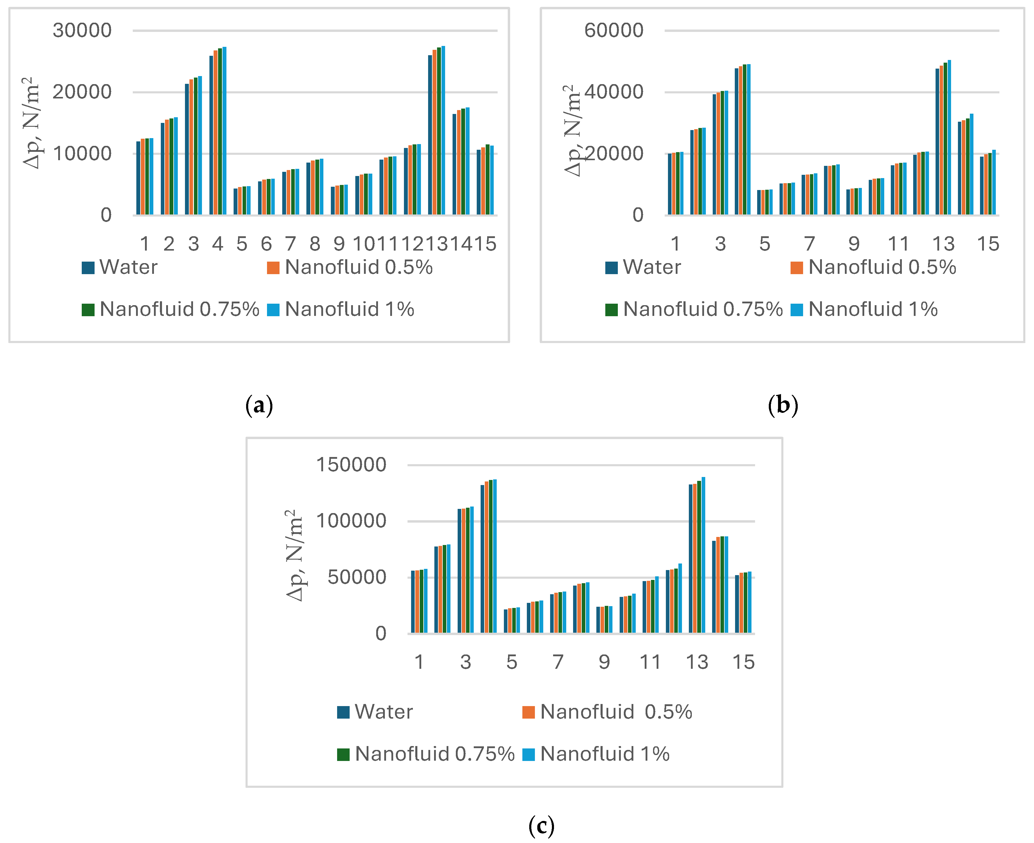
4.2. Changing Water with Nanofluids as a Cooling Medium
4.3. Changing the Plate Material
5. Conclusions
Author Contributions
Funding
Data Availability Statement
Conflicts of Interest
Nomenclature
| Ach | channel cross-sectional free flow area, m2 |
| Ach,sine | the cross-sction area transverse to the furrow, m2 |
| Ae | heat transfer total area, m2 |
| b | corrugation depth, amplitude of sinusoidal duct, m |
| cp | specific heat capacity, J/kg K |
| dh | hydraulic diameter, m |
| dh,sine | hydraulic diameter of sine duct, m |
| f | friction factor (Equation (12)) |
| fapp | apparent friction factor (Equation (3)) |
| Gch | mass flow in the channel, kg/m2 s |
| Gp | mass flow in the port, kg/m2 s |
| h | partial heat transfer coefficient, W/m2 K |
| Leff | plate length between ports, effective length, m |
| Lfurr | the furrow characteristic length, m |
| l | plate pitch, corrugation wavelength, m |
| mass flowrate in the channel, kg/s | |
| Ncp | number of channels for one pass |
| Np | number of fluid passes |
| Nt | total number of plates |
| Nu | |
| Nusine | Nusselt number taking into consideration the sine duct (Equation (1)) |
| Pr | |
| Resine | Reynolds number related to sine duct (Equation (4)) |
| U | overall heat transfer coefficient, W/m2 K |
| usine | the average velocity in the cell’s sine duct in furrow direction, m/s |
| Greek symbols | |
| Β | corrugation inclination angle relative to vertical direction, ° |
| δ | plate thickness, m |
| Δp | pressure drop, N/m2 |
| λ | thermal conductivity, W/m K |
| μ | dynamic visosity, kg/m s |
| Subscripts | |
| c | related to the cold fluid |
| ch | channel |
| h | related to hot fluid |
| sine | sine duct |
| w | at the wall |
References
- Yang, J.; Jacobi, A.; Liu, W. Heat transfer correlations for single-phase flow in plate heat exchangers based on experimental data. App. Therm. Eng. 2017, 113, 1547–1557. [Google Scholar] [CrossRef]
- Hedayati, S.; Ansarifar, E.; Jafari, M.S. Thermal Processing of Food Products by Steam and Hot Water; Elsevier: Cambridge, UK, 2023; pp. 111–128. [Google Scholar]
- Arsenyeva, O.; Tovazhnyanskyy, L.; Kapustenko, P.; Klemeš, J.J.; Varbanov, P.S. Review of Developments in Plate Heat Exchanger Heat Transfer Enhancement for Single-Phase Applications in Process Industries. Energies 2023, 16, 4976. [Google Scholar] [CrossRef]
- Kumar, S.; Kumar Singh, S.; Sharma, D. Comprehensive Review on Thermal Performance Enhancement of Plate Heat Exchanger. Int. J.Thermophys. 2022, 43, 109. [Google Scholar] [CrossRef]
- Sri Valli, G.; Kommineni, R.; Sreedhara Rao, B. A Literature Review on Corrugated Plate Heat Exchanger. Mater. Today 2019, 18, 320–326. [Google Scholar] [CrossRef]
- Elmaaty, T.M.A.; Kabeel, A.E.; Mahgoub, M. Corrugated plate heat exchanger review. Renew. Sust. Energy Rev. 2017, 70, 852–860. [Google Scholar] [CrossRef]
- Panday, N.K.; Singh, S.N. Study of thermo-hydraulic performance of chevron type plate heat exchanger with wire inserts in the channel. Int. J. Therm. Sci. 2021, 173, 107360. [Google Scholar] [CrossRef]
- Nguyen, D.H.; Kim, K.M.; Shim, G.H.; Kim, J.H.; Lee, C.H.; Lim, S.T.; Ahn, S.H. Experimental study on the thermal-hydraulic performance of modified chevron plate heat exchanger by electrochemical etching method. Int. J. Heat Mass Transf. 2020, 155, 119857. [Google Scholar] [CrossRef]
- Khail, A.A.; Erișen, A. Heat transfer and performance enhancement investigation of novel plate heat exchanger. Therm. Sci. Eng. Prog. 2022, 34, 101368. [Google Scholar] [CrossRef]
- Piper, M.; Zibart, A.; Kenig, E.Y. Design equations for turbulent forced convection heat transfer and pressure loss in pillow-plate channels. Int. J. Therm. Sci. 2017, 120, 459–468. [Google Scholar] [CrossRef]
- Syam Sundar, L.; Chandra Mouli, K.V.V. Effectiveness and number of transfer units of plate heat exchanger with Fe3O4–SiO2/Water hybrid nanofluids: Experimental and artificial neural network predictions. Case Stud. Therm. Eng. 2024, 53, 103949. [Google Scholar] [CrossRef]
- Ajeeb, W.; Thieleke da Silva, R.R.S.; Sohel Murshed, S.M. Experimental investigation of heat transfer performance of Al2O3 nanofluids in a compact plate heat exchanger. Appl. Therm. Eng. 2023, 218, 119321. [Google Scholar] [CrossRef]
- Chen, T.; Kim, J.; Cho, H. Theoretical analysis of the thermal performance of a plate heat exchanger at various chevron angles using lithium bromide solution with nanofluid. Int. J. Refrig. 2014, 48, 233–244. [Google Scholar] [CrossRef]
- Syam Sundar, L. Synthesis and characterization of hybrid nanofluids and their usage in different heat exchangers for improved heat transfer rates: A critical review. Eng. Sci. Technol. Int. J. 2023, 44, 101468. [Google Scholar] [CrossRef]
- Liu, M.-S.; Lin, M.-C.-C.; Huang, I.-T.; Wang, C.-C. Enhancement of thermal conductivity with carbon nanotube for nanofluids. Int. Comm. Heat Mass Transf. 2005, 32, 1202–1210. [Google Scholar] [CrossRef]
- Tiwari, A.K.; Ghosh, P.; Sarkar, J. Heat transfer and pressure drop characteristics of CeO2/water nanofluid in plate heat exchanger. Appl. Therm. Eng. 2013, 57, 24–32. [Google Scholar] [CrossRef]
- Kiepfer, H.; Stannek, P.; Grundler, M.; Bart, H.-J. Development and thermal performance of a thermoplastic-graphite-composite based plate heat exchanger for use in corrosive media. App. Therm. Eng. 2024, 236, 121581. [Google Scholar] [CrossRef]
- Nguyen, D.H.; Kim, K.M.; Nguyen Vo, T.T.; Shim, G.H.; Kim, J.H.; Ahn, H.S. Improvement of thermal-hydraulic performance of plate heat exchanger by electroless nickel, copper and silver plating. Case Stud. Therm. Eng. 2021, 23, 100797. [Google Scholar] [CrossRef]
- Wajs, J.; Mikielewicz, D. Influence of metallic porous microlayer on pressure drop and heat transfer of stainless steel plate heat exchanger. Appl. Therm. Eng. 2016, 93, 1337–1346. [Google Scholar] [CrossRef]
- Kakaç, S.; Liu, H. Heat Exchangers. Selection, Rating and Thermal Design, 2nd ed.; CRC Press: Boca Raton, FL, USA, 2002. [Google Scholar]
- Arsenyeva, O.; Tovazhnyansky, L.; Kapustenko, P.; Khavin, G. Mathematical Modelling and Optimal Design of Plate-and-Frame Heat Exchangers. Chem. Eng. Trans. 2009, 18, 791–796. [Google Scholar]
- Martin, H. A theoretical approach to predict the performance of chevron-type plate heat exchangers. Chem. Eng. Process Process. Intensif. 1996, 35, 301–310. [Google Scholar] [CrossRef]
- Stephan, P. VDI Heat Atlas; Springer: Berlin/Heidelberg, Germany, 2010. [Google Scholar]
- Flynn, A.M.; Akashige, T.; Theodore, L. Kern’s Process Heat Transfer, 2nd ed.; Scrivener Publishing LLC: Beverly, MA, USA, 2019. [Google Scholar]
- Miller, E. Heat Exchanger Design Handbook; NY Research Press: New York, NY, USA, 2015. [Google Scholar]
- Dović, D.; Palm, B.; Švaić, S. Generalized correlations for predicting heat transfer and pressure drop in plate heat exchanger channels of arbitrary geometry. Int. J. Heat Mass Transf. 2009, 52, 4553–4563. [Google Scholar] [CrossRef]
- Neagu, A.A.; Koncsag, C.I. Model Validation for the Heat Transfer in Gasket Plate Heat Exchangers Working with Vegetable Oils. Processes 2022, 10, 102. [Google Scholar] [CrossRef]
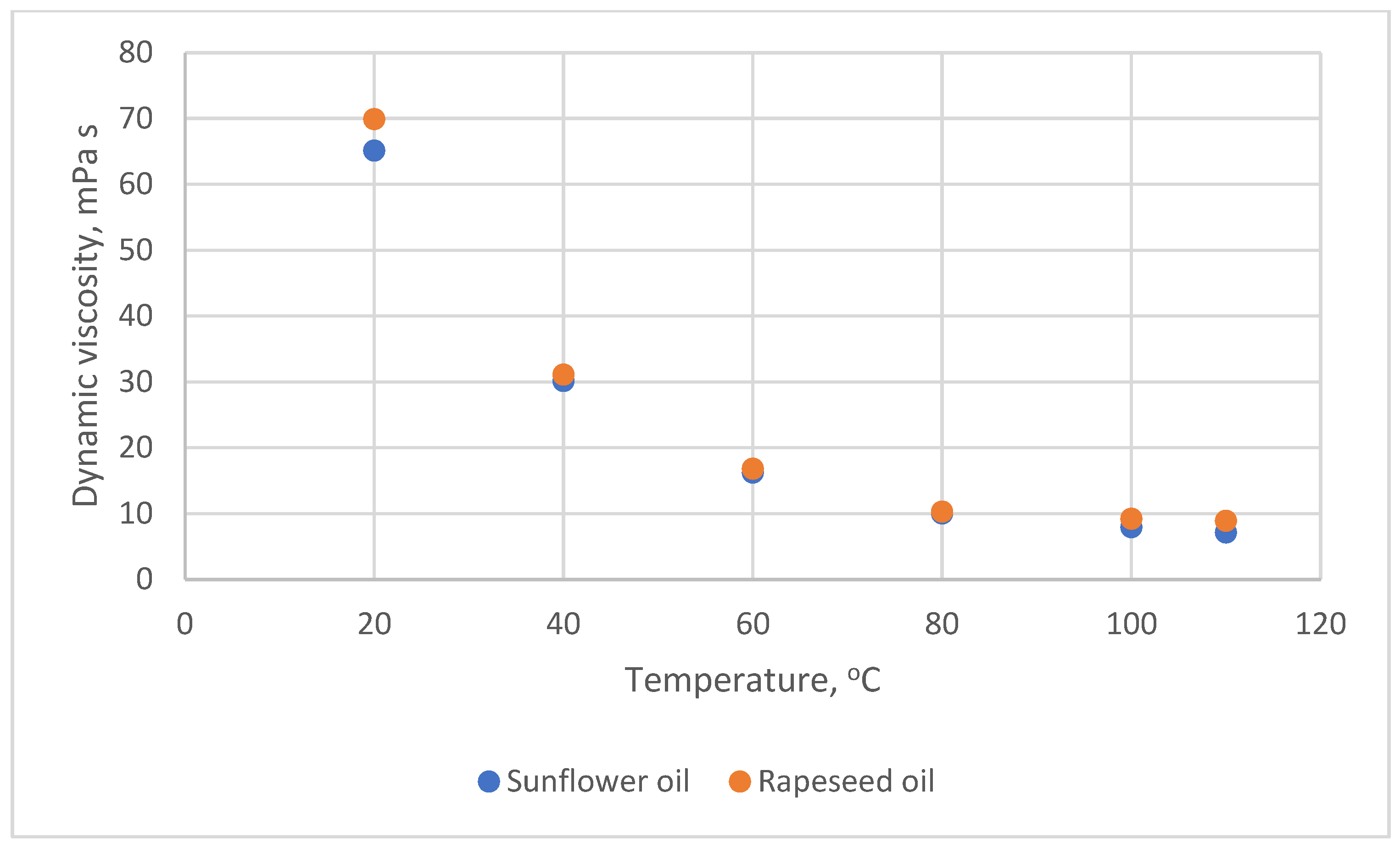
- Hoffmann, J.-F.; Vaitilingom, G.; Henry, J.-F.; Chirtoc, M.; Olives, R.; Goetz, V.; Py, X. Temperature dependence of thermophysical and rheological properties of seven vegetable oils in view of their use as heat transfer fluids in concentrated solar plants. Sol. Energy Mater. Sol. Cells 2018, 178, 129–138. [Google Scholar] [CrossRef]
- Sadeghianjahromi, A.; Jafari, A.; Wang, C.-C. Numerical investigation of the effect of chevron angle on thermofluids characteristics of non-mixed and mixed brazed plate heat exchangers with experimental validation. Int. J. Heat Mass Transf. 2022, 184, 122278. [Google Scholar] [CrossRef]
- Kumar Tiwari, A.; Said, Z.; Pandya, N.S.; Shah, H. Effect of plate spacing and inclination angle over the thermal performance of plate heat exchanger working with novel stabilized polar solvent-based silicon carbide nanofluid. J. Energy Storage 2023, 60, 106615. [Google Scholar] [CrossRef]
- Khan, A.A.; Danish, M.; Rubaiee, S.; Yahya, S.M. Insight into the investigation of Fe3O4/SiO2 nanoparticles suspended aqueous nanofluids in hybrid photovoltaic/thermal system. Clean. Eng. Technol. 2022, 11, 100572. [Google Scholar] [CrossRef]
- Alklaibi, A.M.; Chandra Mouli, K.V.V.; Syam Sundar, L. Heat transfer, and friction factor of Fe3O4–SiO2/Water hybrid nanofluids in a plate heat exchanger: Experimental and ANN predictions. Int. J.Therm. Sci. 2024, 195, 108608. [Google Scholar] [CrossRef]
- Muley, A.; Manglik, R.M. Experimental study of turbulent flow heat transfer and pressure drop in a plate heat exchanger with chevron plates. ASME J. Heat Transfer 1999, 121, 110–117. [Google Scholar] [CrossRef]
- Muley, A.; Manglik, R.M.; Metwally, H.M. Enhanced heat transfer characteristics of viscous liquid flows in a chevron plate heat exchanger. ASME J. Heat Transfer 1999, 121, 1011–1017. [Google Scholar] [CrossRef]
- Okada, K.; Ono, M.; Tomimura, T.; Okuma, T.; Konno, H.; Ohtani, S. Design and heat transfer characteristics of new plate heat exchanger. Heat Transfer Jpn. Res. 1972, 1, 90–95. [Google Scholar]
- Naik, V.R.; Matawala, V.K. Expermental investigation of single phase chevron type heat exchanger. J. Therm. Sci. Eng. Appl. 2013, 2, 362–369. [Google Scholar]
- Gherasim, I.; Taws, M.; Galanis, N.; Nguyen, C.T. Heat transfer and fluid flow in a plate heat exchanger. Part I. Experimental investigation. Int. J.Therm. Sci. 2011, 50, 1492–1498. [Google Scholar] [CrossRef]
- Miura, R.Y.; Galeazzo, F.C.C.; Tadini, C.C.; Gut, J.A.W. The effect of flow arrangement on the pressure drop of plate heat exchangers. Chem. Eng. Sci. 2008, 63, 5386–5393. [Google Scholar] [CrossRef]
- Zhu, X.; Haglind, F. Relationship between inclination angle and friction factor of chevron-type plate heat exchangers. Int. J. Heat Mass Transf. 2020, 162, 120370. [Google Scholar] [CrossRef]
- Ponticorvo, E.; Iuliano, M.; Cirillo, C.; Maiorino, A.; Aprea, C.; Sarno, M. Fouling Behavior and Dispersion Stability of Nanoparticle-Based Refrigeration Fluid. Energies 2022, 15, 3059. [Google Scholar] [CrossRef]
- London Metals Exchange. Available online: https://lme.com/en/Metals/Non-ferrous/LME-Aluminium-Alloy#Summary (accessed on 23 December 2024).
- Made in China. Connecting Buyers with Chinese Suppliers. Available online: https://made-in-china.com/products-search/hot-china-products/316l_Stainless_Steel_Price.html (accessed on 23 December 2024).

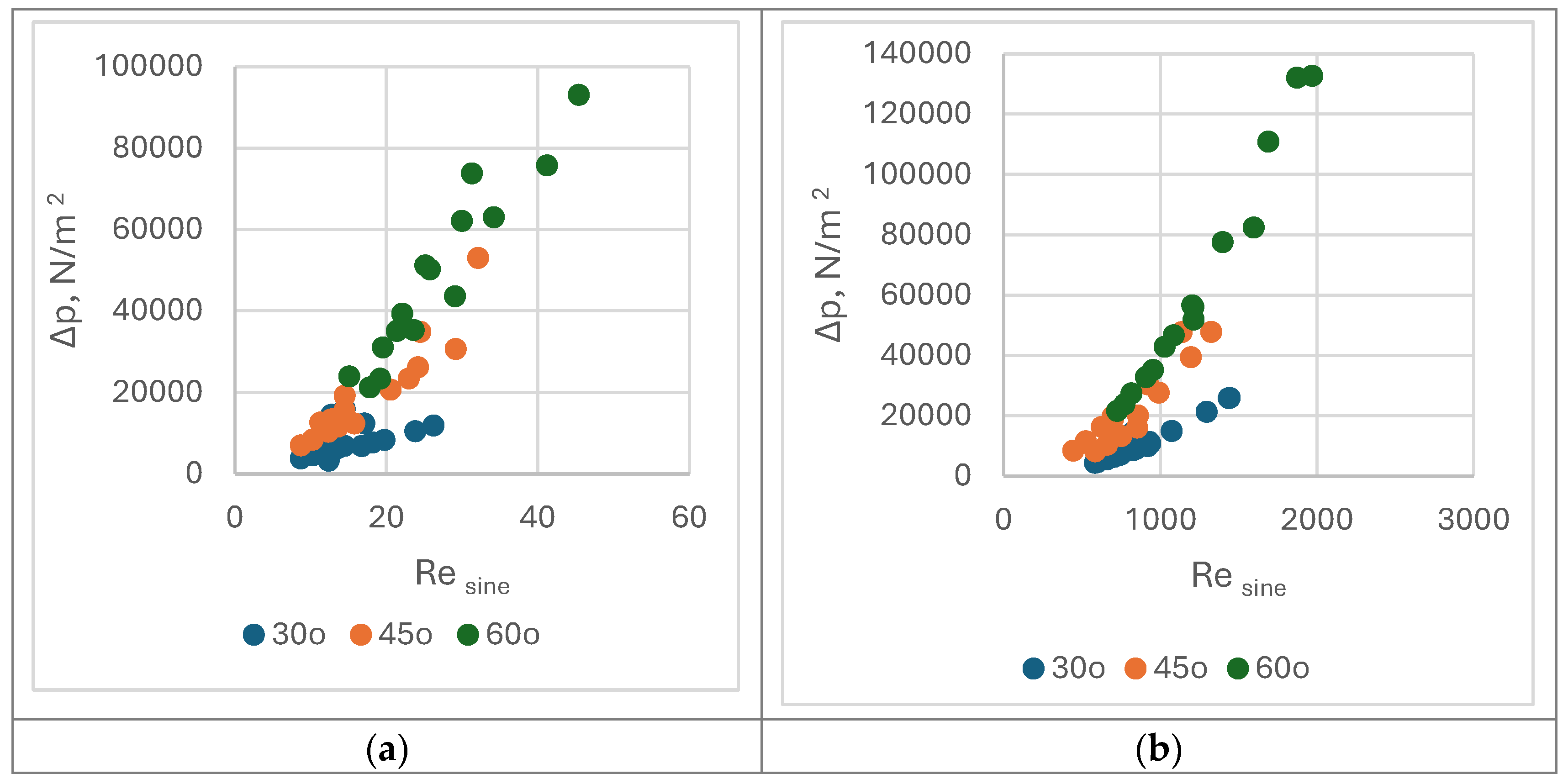
 30°,
30°,  45°, and
  60°. (b). Nusine vs. Resine on water side of PHEs with corrugation inclination angle relative to vertical direction β = 30°, 45°, and 60°.
30°, 45°, and 60°. (b). Nusine vs. Resine on water side of PHEs with corrugation inclination angle relative to vertical direction β = 30°, 45°, and 60°.
60°. (b). Nusine vs. Resine on water side of PHEs with corrugation inclination angle relative to vertical direction β = 30°, 45°, and 60°.
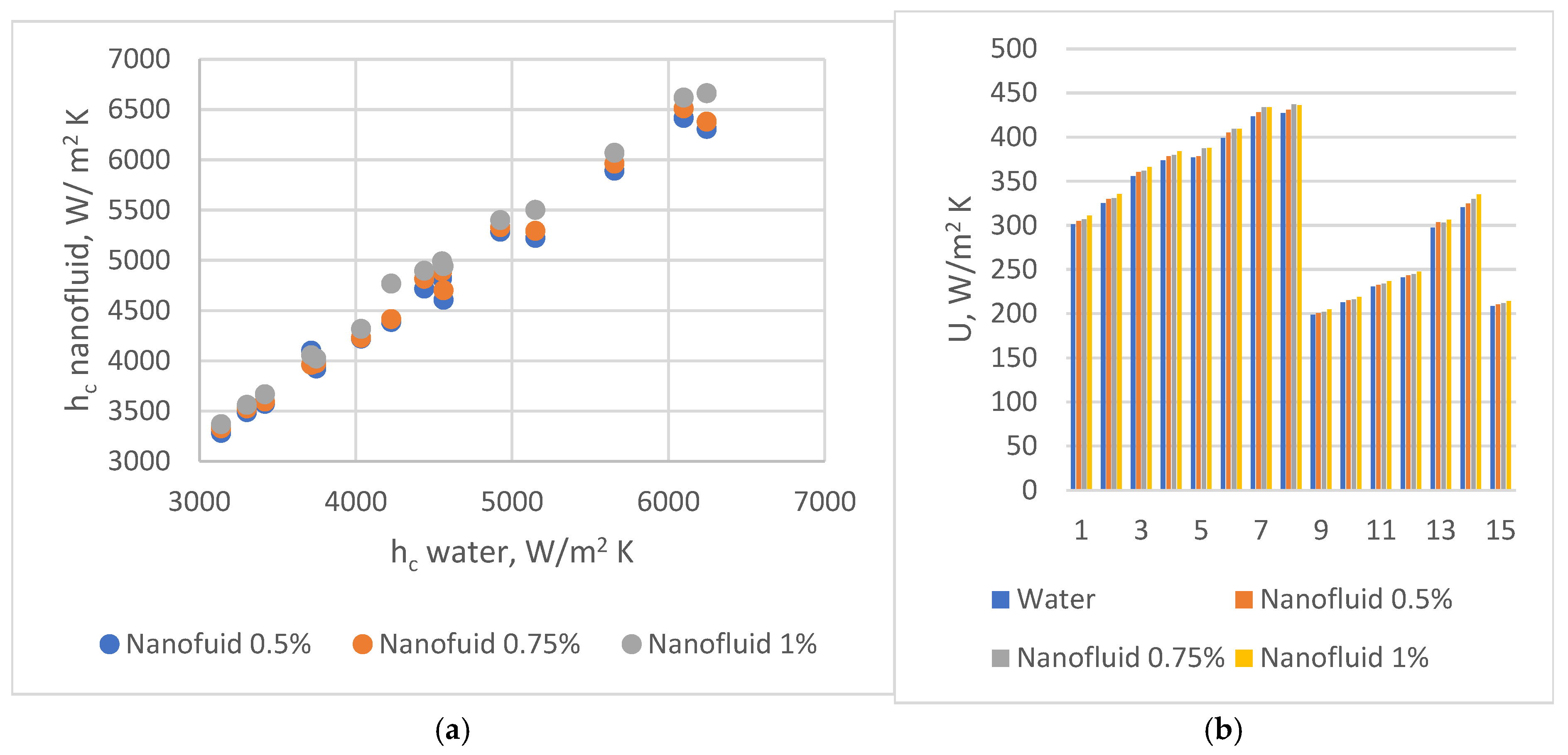
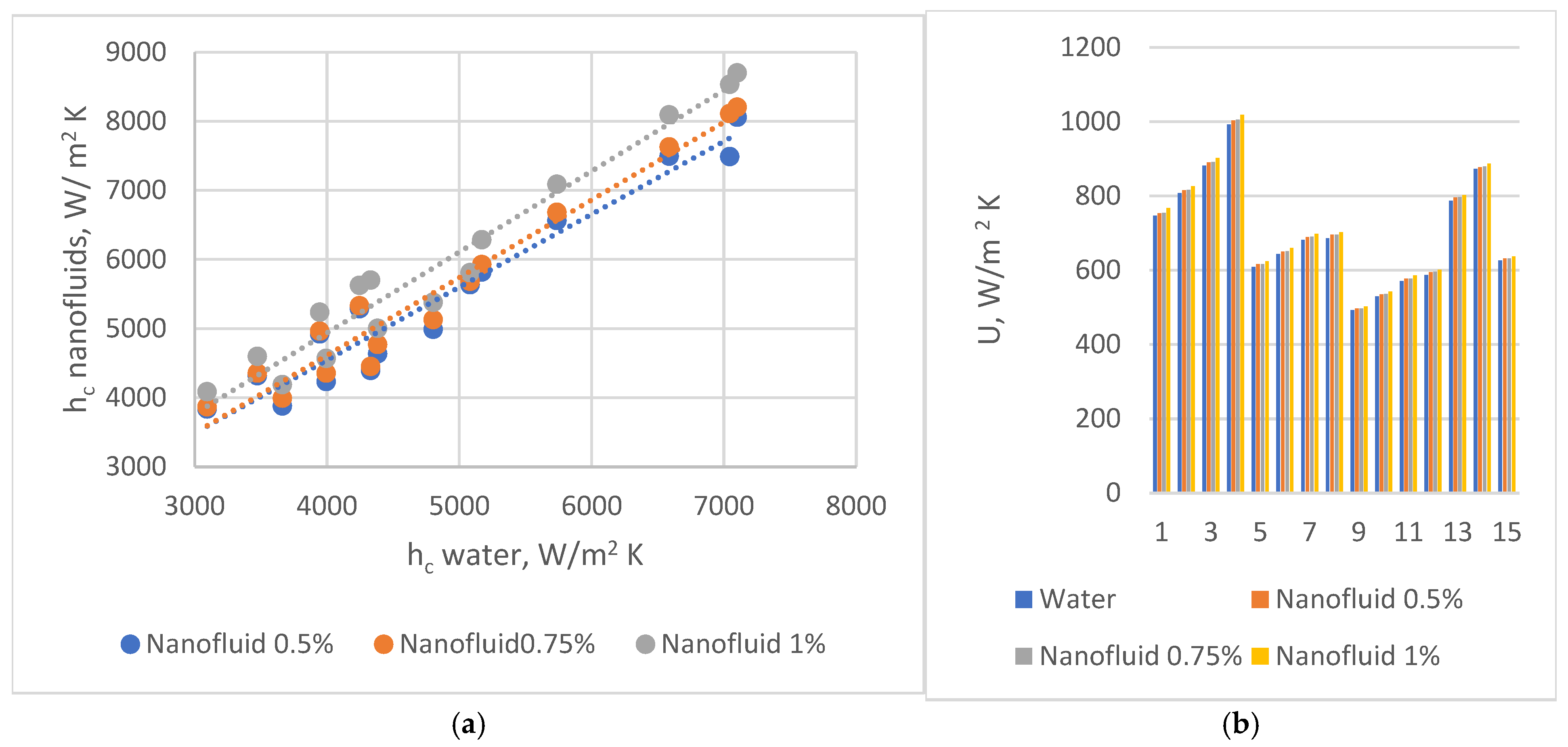
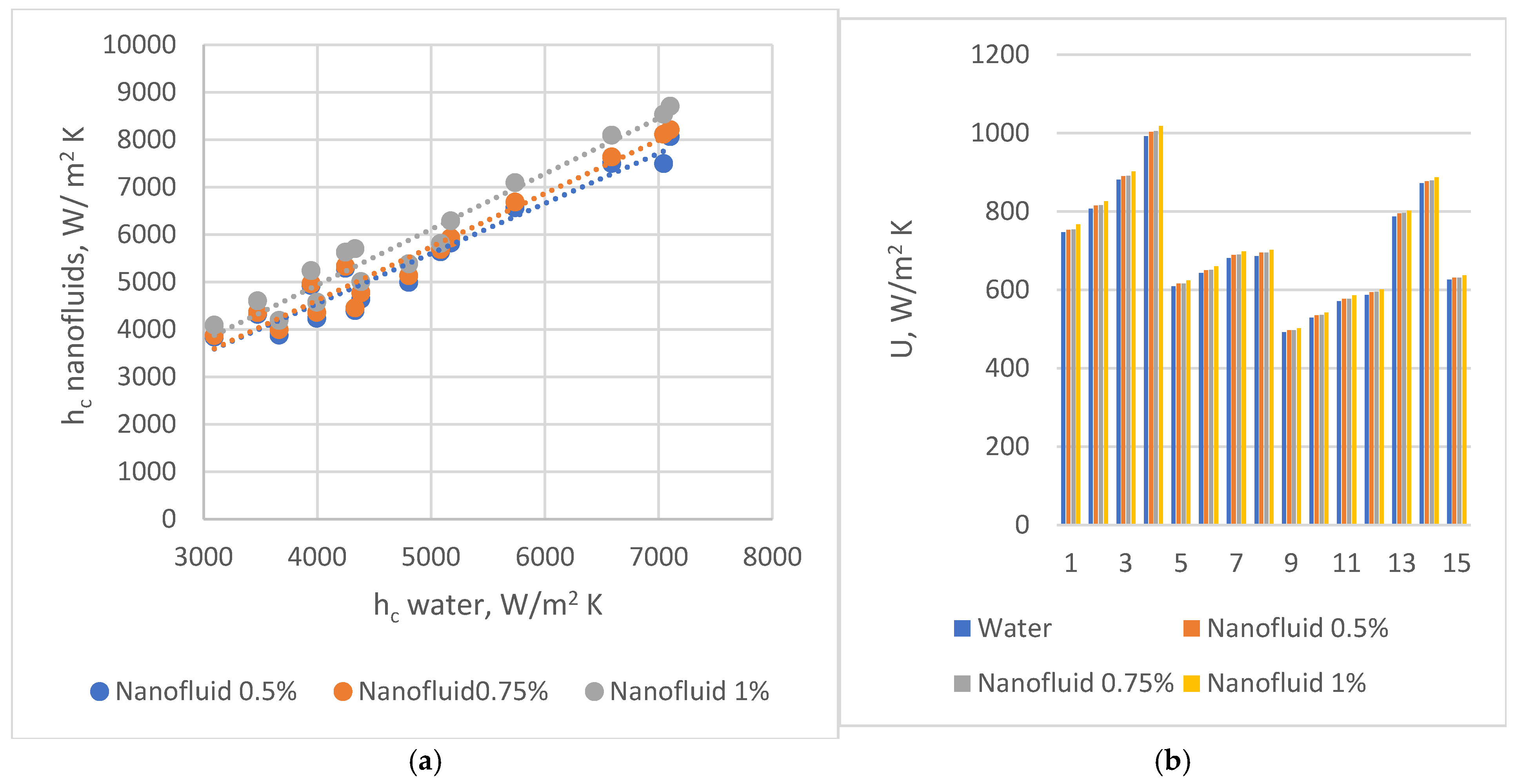
30°, 45°, and 60°. (b). Nusine vs. Resine on water side of PHEs with corrugation inclination angle relative to vertical direction β = 30°, 45°, and 60°.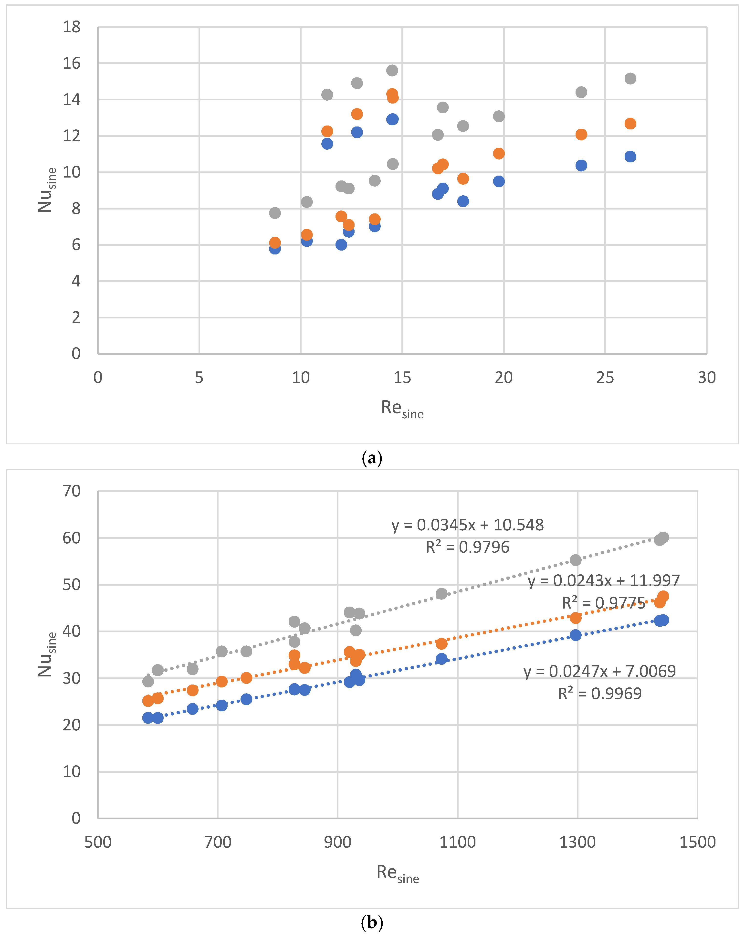 , 45° , and 60° . (b) Partial heat transfer coefficients on water side in PHEs with corrugation inclination angle relative to vertical direction β = 30° , 45° , and 60° .
, 45° , and 60° . (b) Partial heat transfer coefficients on water side in PHEs with corrugation inclination angle relative to vertical direction β = 30° , 45° , and 60° .
, 45° , and 60° . (b) Partial heat transfer coefficients on water side in PHEs with corrugation inclination angle relative to vertical direction β = 30° , 45° , and 60° .


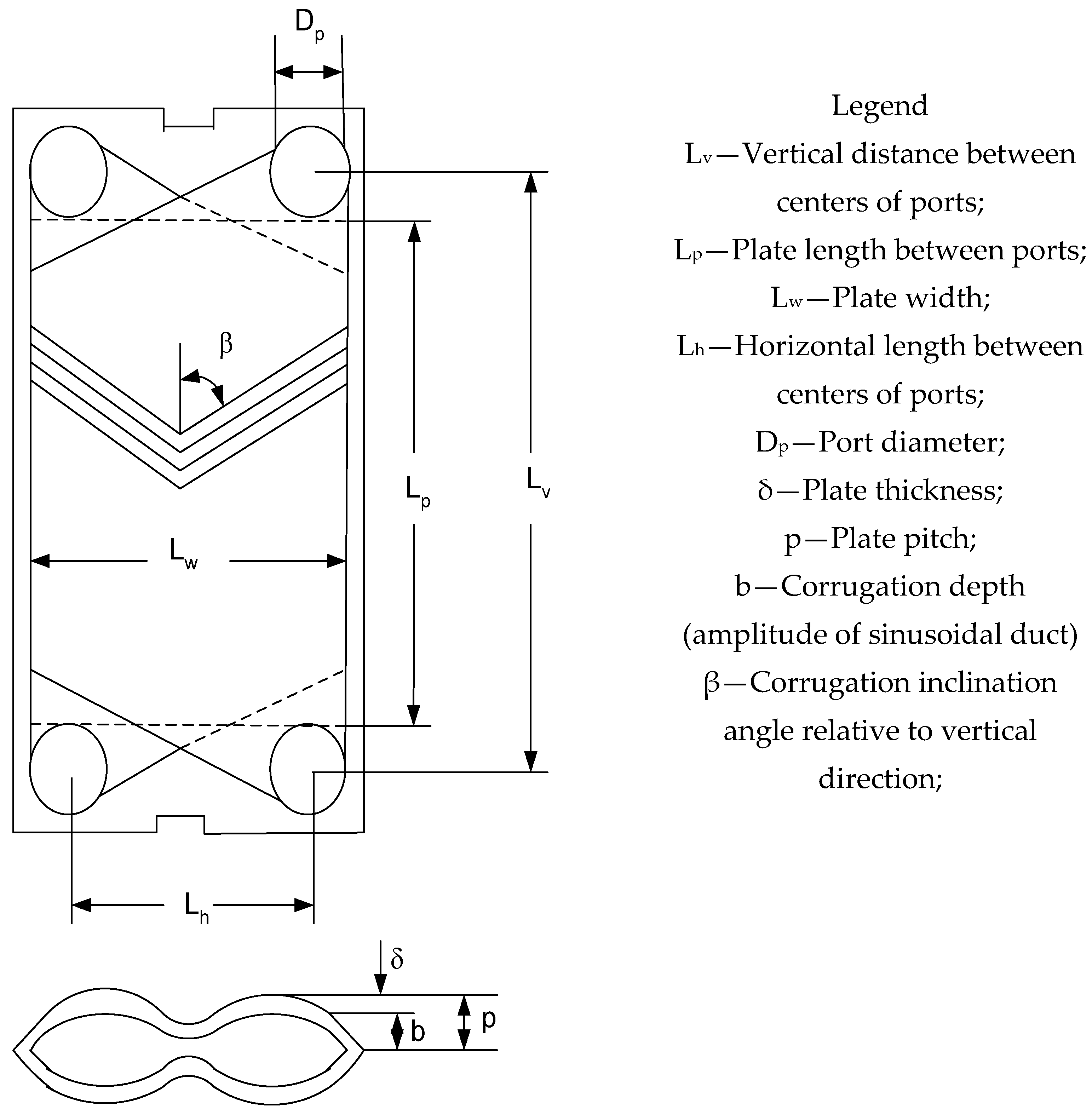
| Geometrical Characteristics of Chevron Plates | Symbol | Heat Exchanger #1 | Heat Exchanger #2 | Heat Exchanger #3 |
|---|---|---|---|---|
| Vertical distance between centers of ports | Lv | 1070 (mm) | 1070 (mm) | 1070 (mm) |
| Plate length between ports (effective length) | Lp (Leff) | 858 (mm) | 858 (mm) | 858 (mm) |
| Plate width | Lw | 450 (mm) | 450 (mm) | 450 (mm) |
| Horizontal length between centers of ports | Lh | 238 (mm) | 238 (mm) | 238 (mm) |
| Port diameter | Dp | 212 (mm) | 212 (mm) | 212 (mm) |
| Plate thickness | δ | 0.6 (mm) | 0.6 (mm) | 0.6 (mm) |
| Plate pitch or corrugation wavelength | p or l | 3.17 (mm) | 3.14 (mm) | 3.14 (mm) |
| Corrugation depth (amplitude of sinusoidal duct) | b | 2.57 (mm) | 2.54 (mm) | 2.55 (mm) |
| Corrugation inclination angle relative to vertical direction | β | 30° | 30° | 30° |
| Surface enlargement factor | φ | 1.17 | 1.17 | 1.17 |
| Hydraulic diameter (=2 b/φ) | dh | 4.396 (mm) | 4.34 (mm) | 4.5 (mm) |
| Channel cross-sectional free flow area | Ach | 1.116 × 10⁻³ (m2) | 1.144 × 10⁻³ (m2) | 1.145 × 10⁻³ (m2) |
| Heat transfer total area | Ae | 11.2 (m2) | 9.2 (m2) | 19.7 (m2) |
| Total number of plates | Nt | 35 | 28 | 63 |
| Number of fluid passes | Np | 1 | 1 | 1 |
| Number of channels for one pass | Ncp | 17 | 13.5 | 31 |
| Exp.# | PHE # | Oil Circuit (Hot Fluid) | Water Circuit (Cold Fluid) | ||||||
|---|---|---|---|---|---|---|---|---|---|
| Mass Flowrate, kg/s | Resine | Nusine | Pr | Mass Flowrate, kg/s | Resine | Nusine | Pr | ||
| 1 | 1 | 1.74 | 17 | 8.8 | 211.09 | 5.25 | 930 | 30.7 | 3.89 |
| 2 | 1 | 2.05 | 20 | 9.5 | 6.20 | 1073 | 34.1 | ||
| 3 | 1 | 2.46 | 24 | 10.4 | 7.43 | 1297 | 39.2 | ||
| 4 | 1 | 2.71 | 26 | 10.9 | 8.21 | 1437 | 42.2 | ||
| 5 | 2 | 1.94 | 11 | 11.6 | 287.5 | 2.55 | 584 | 21.5 | 3.89 |
| 6 | 2 | 2.19 | 13 | 12.2 | 2.88 | 658 | 23.4 | ||
| 7 | 2 | 2.49 | 15 | 12.9 | 3.27 | 748 | 25.7 | ||
| 8 | 2 | 2.78 | 15 | 12.9 | 3.62 | 828 | 27.7 | ||
| 9 | 3 | 1.77 | 9 | 5.8 | 151.0 | 6.02 | 600 | 21.5 | 3.68 |
| 10 | 3 | 1.48 | 10 | 6.2 | 7.11 | 707 | 24.2 | ||
| 11 | 3 | 1.83 | 12 | 6.7 | 8.52 | 845 | 27.5 | ||
| 12 | 3 | 1.95 | 14 | 7.0 | 9.41 | 936 | 29.6 | ||
| 13 | 1 | 2.72 | 18 | 8.4 | 202.15 | 8.23 | 1443 | 42.4 | 3.89 |
| 14 | 2 | 2.76 | 17 | 9.1 | 267.11 | 3.62 | 828 | 27.6 | 3.89 |
| 15 | 3 | 2.72 | 12 | 6.0 | 167.37 | 9.44 | 920 | 29.2 | 3.68 |
| Data set # | U30° | U45° | U60° | (%) 30–45 | (%) 45–60 | 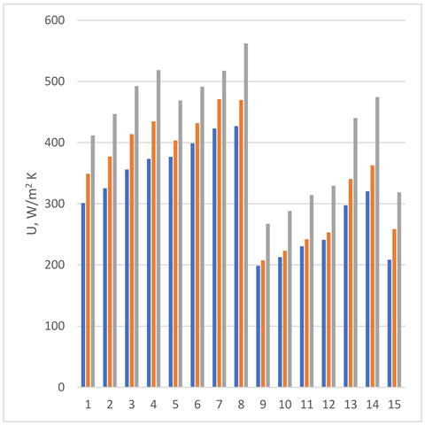 |
| 1 | 301 | 349 | 412 | 15.8 | 20.8 | |
| 2 | 325 | 377 | 447 | 15.9 | 21.4 | |
| 3 | 356 | 414 | 492 | 16.2 | 22.1 | |
| 4 | 373 | 435 | 518 | 16.4 | 22.4 | |
| 5 | 377 | 403 | 469 | 7.0 | 17.3 | |
| 6 | 399 | 432 | 491 | 8.3 | 14.9 | |
| 7 | 423 | 471 | 517 | 11.3 | 11.0 | |
| 8 | 427 | 469 | 562 | 10.0 | 21.7 | |
| 9 | 199 | 208 | 267 | 4.5 | 30.0 | |
| 10 | 213 | 223 | 288 | 4.9 | 30.6 | |
| 11 | 230 | 242 | 314 | 5.0 | 31.3 | |
| 12 | 241 | 253 | 329 | 5.0 | 31.6 | |
| 13 | 298 | 341 | 440 | 14.5 | 33.4 | |
| 14 | 320 | 363 | 474 | 13.3 | 34.8 | |
| 15 | 209 | 258 | 319 | 23.9 | 28.8 | |
| Average increase, % | 11.5 | 24.8 | ||||
 chevron angle 30°;
  chevron angle 45°;
  chevron angle 60°.
| Data Set # | U [W/m2 K] β = 30° Fluid: Water Stainless Steel Plate Base Case | U [W/m2 K] β = 60° Nanofluid 1%, Stainless Steel Plate | U [W/m2 K] β = 60° Nanofluid 1% Alloy 6060 Plate Final choice | U Increasing for Changing the Material β = 60° Nanofluid 1% | U Increasing From the Base Case to Final Choice % |
|---|---|---|---|---|---|
| 1 | 301 | 427 | 435 | 2.0 | 44.5 |
| 2 | 325 | 461 | 471 | 2.3 | 44.8 |
| 3 | 356 | 510 | 523 | 2.6 | 46.8 |
| 4 | 373 | 533 | 547 | 2.7 | 46.5 |
| 5 | 377 | 490 | 501 | 2.3 | 33.0 |
| 6 | 399 | 514 | 526 | 2.5 | 32.0 |
| 7 | 423 | 540 | 554 | 2.6 | 30.9 |
| 8 | 427 | 378 | 555 | 2.7 | 30.1 |
| 9 | 199 | 273 | 278 | 1.5 | 39.8 |
| 10 | 213 | 296 | 301 | 1.7 | 41.3 |
| 11 | 230 | 323 | 329 | 1.9 | 42.6 |
| 12 | 241 | 348 | 355 | 2.0 | 47.2 |
| 13 | 298 | 455 | 404 | 4.1 | 35.7 |
| 14 | 320 | 532 | 456 | 4.5 | 42.3 |
| 15 | 209 | 330 | 333 | 3.0 | 59.7 |
| Average increase: | 2.6% | 41.2% | |||
Disclaimer/Publisher’s Note: The statements, opinions and data contained in all publications are solely those of the individual author(s) and contributor(s) and not of MDPI and/or the editor(s). MDPI and/or the editor(s) disclaim responsibility for any injury to people or property resulting from any ideas, methods, instructions or products referred to in the content. |
© 2025 by the authors. Licensee MDPI, Basel, Switzerland. This article is an open access article distributed under the terms and conditions of the Creative Commons Attribution (CC BY) license (https://creativecommons.org/licenses/by/4.0/).
Share and Cite
Neagu, A.-A.; Koncsag, C.I. Improving the Thermal Efficiency of Gasket Plate Heat Exchangers Used in Vegetable Oil Processing. Inventions 2025, 10, 10. https://doi.org/10.3390/inventions10010010
Neagu A-A, Koncsag CI. Improving the Thermal Efficiency of Gasket Plate Heat Exchangers Used in Vegetable Oil Processing. Inventions. 2025; 10(1):10. https://doi.org/10.3390/inventions10010010
Chicago/Turabian StyleNeagu, Anișoara-Arleziana, and Claudia Irina Koncsag. 2025. "Improving the Thermal Efficiency of Gasket Plate Heat Exchangers Used in Vegetable Oil Processing" Inventions 10, no. 1: 10. https://doi.org/10.3390/inventions10010010
APA StyleNeagu, A.-A., & Koncsag, C. I. (2025). Improving the Thermal Efficiency of Gasket Plate Heat Exchangers Used in Vegetable Oil Processing. Inventions, 10(1), 10. https://doi.org/10.3390/inventions10010010