Communication

Link Characteristics Comparison of Lambertian & Non-Lambertian MIMO-Based 6G Vehicular Visible Light Communications

1
College of Technology and Data, Yantai Nanshan University, Yantai 265713, China
2
Key Laboratory of Signal Detection and Processing in Xinjiang Uygur Autonomous Region, School of Computer Science and Technology (School of Cyberspace Security), Xinjiang University, Urumqi 830046, China
3
China Mobile Research Institute, Beijing 100053, China
4
Department of Electronic Engineering, Beijing National Research Center for Information Science and Technology, Tsinghua University, Beijing 100084, China
*
Author to whom correspondence should be addressed.
Inventions 2025, 10(1), 1; https://doi.org/10.3390/inventions10010001
Submission received: 19 November 2024 / Revised: 24 December 2024 / Accepted: 28 December 2024 / Published: 28 December 2024

Abstract

:
As one key candidate technology for the 6G internet of vehicles, vehicular visible light communications (VLCs) have received widespread attention and discussion due to their inherent advantages, including broadband, green, security, and ubiquity. In order to improve the quality of vehicular VLC links and extend their coverage, various multiple input multiple output (MIMO) techniques have been actively introduced into the field of vehicular VLC, demonstrating the corresponding performance gain potential. Objectively, the existing research works mentioned above are generally limited to the discussion of MIMO vehicular VLC based on conventional Lambertian light-emitting diode (LED) light sources. Consequently, there is one absence of a targeted study and evaluation of the link configuration-based vehicular non-Lambertian LEDs and the potential non-Lambertian MIMO vehicular VLC. To address the limitations of the aforementioned research and explore the novel spatial dimension for vehicular VLC design, this work attempts to introduce the representative non-Lambertian LED light beams into the typical MIMO vehicular VLC application for constructing novel MIMO vehicular VLC transmission links. The numerical results demonstrate that in 2 × 2 MIMO mode, compared to the benchmark Lambertian vehicular VLC scheme, the proposed typical non-Lambertian NSPW vehicular VLC schemes could provide capacity gains of up to 5.18 bps/Hz and 4.71 bps/Hz for the stop mode, and the traffic mode, respectively. Moreover, this article quantitatively evaluates the impact of the spatial spacing of receiver light beams on the performance of MIMO vehicular VLC and the relevant fundamental characteristics.

1. Introduction

Vehicular communication plays a significant role in the internet of vehicles, intelligent transportation systems, automatic driving, and vehicle-to-everything applications [1,2,3,4]. Recently, with the data interaction having increased significantly for vehicle-to-vehicle (V2V) and vehicle-to-infrastructure (V2I), it has been witnessed that the mature radio frequency (RF) technology could not independently support the diverse vehicular communication application due to intractable electromagnetic interference, serious spectrum congestion, potential security vulnerability, and increased multipath propagation delay [5,6,7,8]. For addressing this challenge, solid-state sources-based vehicular visible light communication (VLC) is receiving increasing attention and becoming one powerful candidate technique, thanks to its sufficient available bandwidth, lower link latency, reduced system power consumption, enhanced security, and lower implementation cost [9,10,11,12].
In the coming sixth generation (6G) era, for successfully applying the Internet of Vehicles (IoV) to ubiquitous and valuable traffic environments, an amount of design and optimization schemes are proposed and studied to enhance the light-emitting diode (LED) transmitters-based multiple input multiple output (MIMO) vehicular VLC performance, especially in short and medium range outdoor scenarios [12,13,14,15]. Specifically, the authors in [15] systematically investigate the novel optimal precoder and equalizer design scheme for the MIMO V2V-VLC system, and the relevant three detection schemes, including zero forcing, maximum likelihood, and minimum mean squared error, are analyzed quantitatively. Moreover, the study in [16] focused on developing a hybrid MIMO V2V communication system based on visible light and radio frequency in order to combine the advantages of both the distinct carrier wave to achieve enhanced range coverage, higher data rate, and smaller bit error rate. Moreover, the authors in [17] investigated the potential impact of various detection algorithms on the performance of 2 × 2 MIMO vehicular VLC systems in terms of symbol error rate and computing time. For utilizing the full spectrum resource of the LED headlights of the vehicular MIMO VLC system, according to the severe uneven frequency response of the LED headlights, one probabilistic shaping bit-loading algorithm was proposed and applied to one typical VLC-based V2X communication system with an achievable rate of 1.84 Gb/s in [18]. Particularly, one multi-agent reinforcement learning (MARL) mechanism was proposed for vehicular VLC systems to evaluate the impact of the rising number of vehicles on energy efficiency and age of information [19].
Nevertheless, almost all the above vehicular VLC works assume that the employed LED sources obey general Lambertian optical beams and could not characterize the potential performance of vehicular MIMO based on non-Lambertian LED optical sources [20,21,22,23,24]. Objectively, the distinct optical beam effects and the relevant design dimension have been introduced and discussed in other representative branch directions of VLC technology, typically including but not limited to channel characteristics evaluation, simultaneous lightwave information and power transfer, non-orthogonal multiple access, coordinated coverage, underwater VLC, physical layer security, and hybrid VLC and radio frequency transmission. Based on the above consideration, it is essential to overcome the research limitation of the current Lambertian beam-based vehicular MIMO works for comparatively characterizing the outdoor vehicular scenarios adopting LED transmitters with distinctive non-Lambertian beam patterns.
Based on the above consideration, in this article, to the best of our knowledge, for the first time, the system models of Lambertian and non-Lambertian MIMO-based 6G vehicular visible light communications are comparatively provided. Meanwhile, the link characteristics comparison of Lambertian and non-Lambertian MIMO-based 6G vehicular visible light communications is investigated and characterized for the 6G internet of vehicles, correspondingly.
In this paper, the vehicular MIMO visible light communications based on distinct light beam configurations are presented in Section 2. The relevant numerical evaluation is presented in Section 3. Finally, Section 4 concludes this paper.
This vital contribution of work includes exploring the effects of the non-Lambertian optical beam on the MIMO link characteristics performance of vehicular visible light communications theoretically. Moreover, the channel models for the MIMO vehicular visible light communications are based on baseline Lambertian optical beam configuration, the typical symmetric and asymmetric non-Lambertian beams. In addition, the effects of the different link distances, the different receiver fields of view, the different receiver spacing, and the receiver aperture size are numerically investigated for the MIMO link characteristics of vehicular visible light communications based on the above distinct optical beam configurations, which pave the way to for the design and optimization techniques via the novel and flexible optical beam dimension for the further developing MIMO vehicular visible light communications and networking.

2. Vehicular MIMO Visible Light Communications Based on Distinct Light Beam Configurations

To a large extent, the channel coefficient and coverage characteristic of vehicular MIMO VLC are dominated or even controlled by the light beam pattern of vehicular LED sources involved in typical outdoor data transmissions. Actually, these distinct light beam patterns objectively create one novel design and innovation dimension for performance evolution and enhancement of vehicular MIMO VLC.

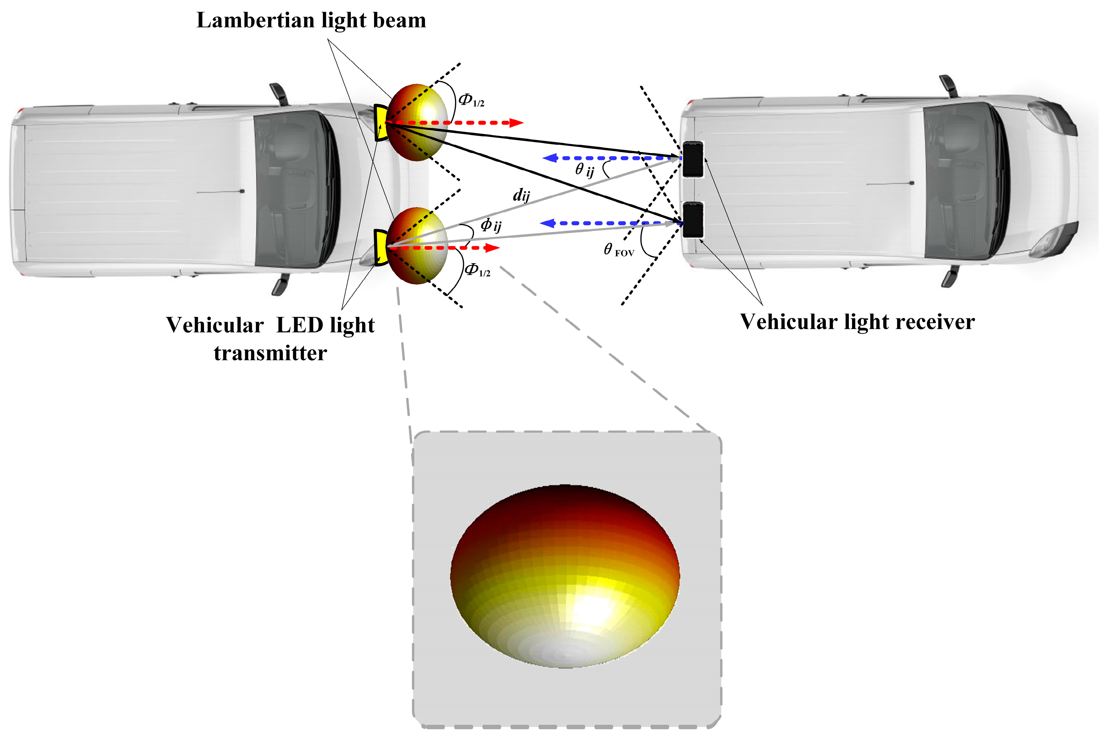
2.1. Vehicular MIMO Visible Light Communications Based on Baseline Lambertian Light Beam Configuration

For one typical vehicular MIMO VLC system with two headlamps to act as the distributed baseline Lambertian light transmitters and two photodiodes (PD) located at the taillights to act as the light receivers, the output signal vector of the receiver is described by [12,13,14,15]:
  y Lam = H Lam x + n ,
where x = [x1, x2]T are emitted signal vector, y Lam = [ y 1 Lam , y 2 Lam ] T are the received signal vector at the receiver of this Lambertian vehicular MIMO VLC system, n = [n1, n2]T are the additive white Gaussian noise (AWGN) vector at the PDs, with [.]T being the transpose operator. Since the well-known baseline Lambertian light beams configuration is adopted in this vehicular MIMO system, the respective channel matrix H Lam is represented by:
  H Lam = H 1 ,     1 Lam H 1 ,     1 atm H 1 ,     2 Lam H 1 ,     2 atm H 2 ,     1 Lam H 2 ,     1 atm H 2 ,     2 Lam H 2 ,     2 atm ,
where the element H i ,     j Lam denotes the channel coefficient between the jth Lambertian LED transmitter and the ith PD receiver, and H i ,     j atm denotes the atmospheric attenuation coefficient between the mentioned Lambertian LED transmitter and PD receiver pair. Specifically, the system model (1) of this vehicular MIMO could be renewed by:
  y 1 Lam y 2 Lam = H 1 ,     1 Lam H 1 ,     1 atm H 1 ,     2 Lam H 1 ,     2 atm H 2 ,     1 Lam H 2 ,     1 atm H 2 ,     2 Lam H 2 ,     2 atm x 1 x 2 +   n 1 n 2 ,
Under such Lambertian light beams configuration, the typical outdoor vehicular MIMO scenario is shown in Figure 1. Accordingly, the above light channel gain coefficient H i ,     j Lam could be given by:
H i , j Lam = R Lam ϕ i , j A PD d i , j 2 T s θ i , j g θ i , j cos θ i , j , 0 θ i , j θ FOV 0 , θ i , j > θ FOV ,
where di,j denotes the distance between the jth light source LED and the ith PD receiver, ϕ i , j denotes the emission angle of the light signal between the mentioned Lambertian LED transmitter and PD receiver pair, θ i , j is the incident angle of the captured optical signal between the mentioned Lambertian LED transmitter and PD receiver pair, A PD denotes the active area of the concerned PD. And θ FOV denotes the field of view (FOV) of the PD receiver while T s θ i , j denotes the gain of the light filter and g θ i , j denotes the gain of the light concentrator, which could be given by [23,24]:
g θ i , j = n 2 sin 2 θ FOV , 0 θ θ FOV 0 , θ > θ FOV ,
where n is the refractive index of the light concentrator. Moreover, in (4), the Lambertian radiation intensity R Lam ϕ i , j is the key metric to describe the spatial radiation characteristics of the baseline Lambertian light beam. Specifically, the respective radiation intensity could be given by:
R Lam ϕ i , j = m Lam + 1 2 π cos m Lam ϕ i , j ,
where the Lambertian index m Lam is explicitly given by:
m Lam = In 2 In cos ϕ 1 / 2 ,
where ϕ 1 / 2 describe the semi-angle at half-power of the average transmitted light source, which models the Lambertian light beam width. Generally, the Lambertian index is set as 1, and the respective 3D radiation pattern is illustrated in Figure 1. By substituting (5) and (6) into (4), the baseline Lambertian light channel gain for this vehicular MIMO VLC could be explicitly renewed as:
H i , j Lam = m Lam + 1 2 π cos m Lam ϕ i , j A PD d i , j 2 T s θ i , j n 2 sin 2 θ FOV cos θ i , j , 0 θ i , j θ FOV 0 , θ i , j > θ FOV ,
In particular, in (3), the atmospheric attenuation coefficient H i ,     j atm could be explicitly given as [9]:
H i   , j atm   = e A atm d i , j ,
where A atm denotes the link visibility, which could be represented as [9]:
A atm = 3.91 V λ 550 q ,
where V denotes the meteorological visibility in km and λ is wavelength in nm, and q is the distribution size of scattering particles, which could be given by Kim’s model [9]:
q = 1.6 , V 50 1.3 , 6 V < 50 0.16 V + 0.34 , 1 V < 6 V 0.5 , 0.5 V < 1 0 , V < 0.5 ,
Then, assuming equal power allocation, the channel capacity of this vehicular MIMO VLC system based on baseline Lambertian light beam could be given by [10]:
C Lam = log 2 det I M + E s N t N 0 H Lam H Lam                     log 2 1 + E s N t N 0 H Lam 2 ,
where N t denotes the amount of LED transmitter, N 0 denotes the single-sided power spectral density of the shot noise, and E s = ρ I 2 T s denotes the mean emitted electrical energy per symbol of the transmitted light signals. The symbol ρ represents the optical-to-electrical conversion coefficient, T s denotes the symbol duration in seconds.
For investigating the error rate performance of the considered vehicular MIMO VLC system based on baseline Lambertian light beam, two different MIMO modes are adopted, i.e., reception coding (RC) and spatial multiplexing (SMP). As for the RC MIMO mode, the resulting end-to-end bit error rate (BER) of M–level pulse amplitude modulation (M-PAM) could be expressed by [11]:
BER RC Lam 2 M 1 M log 2 M Q 1 M 1 E s N 0 N t 2 i = 1 N r j = 1 N t H i , j Lam H i   , j atm 2 ,
where M denotes the signal constellation size, and the Q function can be given by:
Q a = 1 2 π α + exp t 2 2 d t .
Moreover, once the SMP MIMO mode is applied, the relevant end-to-end BER of M-PAM could be renewed by [11]:
BER SMP Lam 1 N t j = 1 N t 2 M j 1 M j log 2 M j Q 1 M j 1 E s N 0 N t 2 W j Lam 2 ,
where M j denotes the selected modulation level for the jth light source LED, and W j Lam denotes the jth row of pseudo-inverse of the channel matrix H Lam , i.e., W Lam which could be given by:
W Lam = H Lam T H Lam 1 H Lam T ,

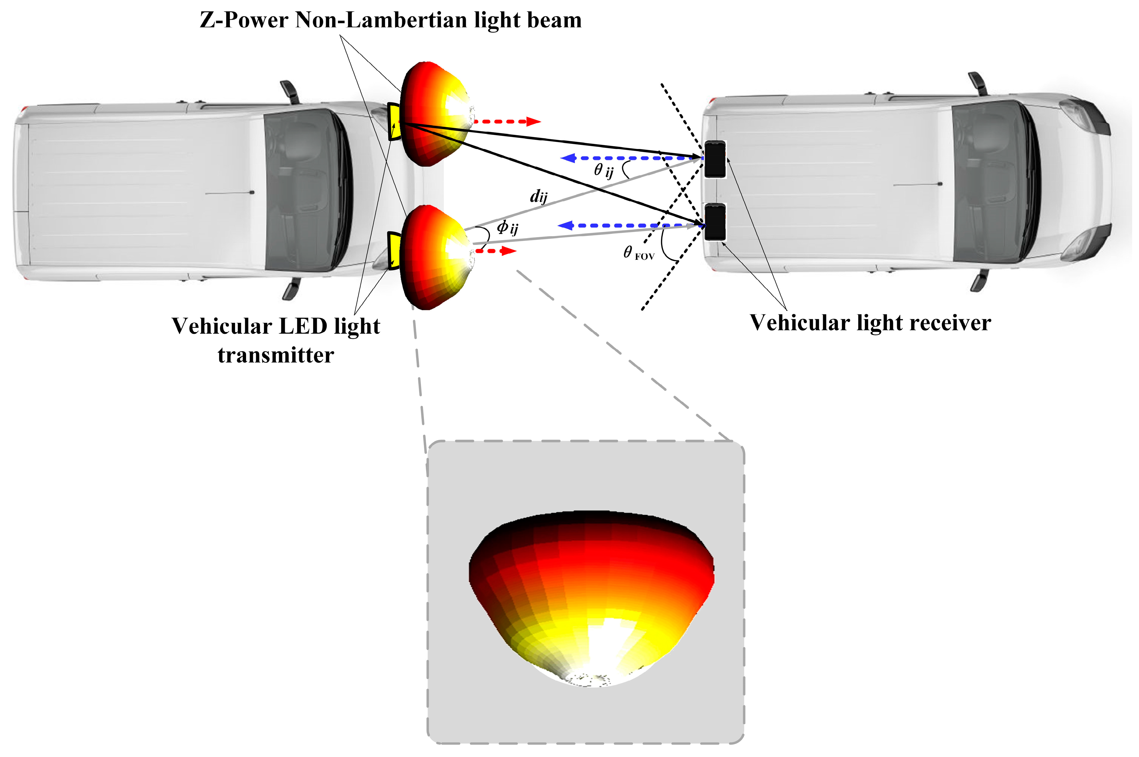
2.2. Vehicular MIMO Visible Light Communications Based on Z-Power Non-Lambertian Light Beam Configuration

Without loss of generality, as typical non-Lambertian light beams, the counterparts from the Z-Power LED and the NSPW345CS Nichia LED are deliberately selected for the following exploration of vehicular MIMO VLC system based on distinct non-Lambertian light beam configuration in this article. The reason for this selection is that, on the one hand, both beams own quite different spatial emission characteristics compared with the conventional Lambertian light beams; on the other hand, both non-Lambertian beams are generated by the commercially available LEDs, which makes this work applicable in vehicular engineering implementation.
Specifically, for the case of vehicular MIMO VLC based on a Z-Power light beam, two headlamps also act as the distributed Z-Power non-Lambertian light transmitters, and two photodiodes (PDs) located at the taillights act as the light receivers, the output signal vector of the receiver is described by:
  y Z - Power = H Z - Power x + n ,
where y Z - Power = [ y 1 Z - Power , y 2 Z - Power ]T are the received signal vector at the receiver of this Z-Power non-Lambertian vehicular MIMO VLC system, H Z - Power denotes the respective channel matrix based on the above Z-Power non-Lambertian light beam configuration, which could be represented by:
  H Z - Power = H 1 ,     1 Z - Power H 1 ,     1 atm H 1 ,     2 Z - Power H 1 ,     2 atm H 2 ,     1 Z - Power H 2 ,     1 atm H 2 ,     2 Z - Power H 2 ,     2 atm
where the element H i ,     j Z - Power denotes the channel coefficient between the jth Z-Power non-Lambertian LED transmitter and the ith PD receiver. Specifically, the system model (17) of this vehicular MIMO could be renewed by:
  y 1 Z - Power y 2 Z - Power = H 1 ,     1 Z - Power H 1 ,     1 atm H 1 ,     2 Z - Power H 1 ,     2 atm H 2 ,     1 Z - Power H 2 ,     1 atm H 2 ,     2 Z - Power H 2 ,     2 atm x 1 x 2 +   n 1 n 2 ,
Under such Z-Power non-Lambertian light beams configuration, the typical outdoor vehicular MIMO scenario is shown in Figure 2. Accordingly, the above light channel gain coefficient H i ,     j Z - Power could be given by:
H i , j Z - Power = R Z - Power ϕ i , j A PD P normZ - Power d i , j 2 T s θ i , j g θ i , j cos θ i , j ,                   0 θ i , j θ FOV 0 ,                                                                                                                                     θ i , j > θ FOV ,
where P normZ - Power denotes the power normalization factor of the Z-Power light beam, which functions to ensure that the beam power radiated in all spatial directions is 1 W, while R Z - Power ϕ i , j denotes the Z-Power non-Lambertian radiation intensity, which could be given by [22]:
R Z - Power ϕ i , j = k = 1 K g 1 k Z - Power exp [ ln 2 ( ϕ i , j g 2 k Z - Power g 3 k Z - Power ) 2 ] ,
where K = 3 is the amount of Gaussian functions. Specifically, the values of coefficients in this expression are g 11 Z - Power = 0.542, g 21 Z - Power = 22.75°, g 31 Z - Power = 49.96°, g 12 Z - Power = 0.573, g 22 Z - Power = 77.84°, g 32 Z - Power = 23.7°, g 13 Z - Power = 0.279, g 23 Z - Power = 86.67°, and g 33 Z - Power = 8.43°. Unlike the previous Lambertian optical beam, in this Z-Power non-Lambertian case, the maximum emission intensity does not appear in the normal direction, i.e., the red arrow direction anymore, but at all directions with an irradiance angle of about 80°. In addition, the respective 3D radiation pattern of the Z-Power light beam is illustrated in Figure 2 as well. By substituting (5) and (21) into (20), the Z-Power non-Lambertian light channel gain for this vehicular MIMO VLC could be explicitly renewed as:
H i , j Z - Power = k = 1 K g 1 k exp [ ln 2 ( ϕ i , j g 2 k g 3 k ) 2 ]   × A PD P normZ - Power d i , j 2 T s θ i , j n 2 sin 2 θ FOV cos θ i , j , 0 θ i , j θ FOV 0 , θ i , j > θ FOV ,
Similarly, assuming equal power allocation, the channel capacity of this vehicular MIMO VLC system based on a Z-Power non-Lambertian light beam could be given by [10]:
C Z - Power = log 2 det I M + E s N 0 N t 2 H Z - Power H Z - Power                 log 2 1 + E s N 0 N t 2 H Z - Power 2 .
At the same time, referring to (13), based on the channel coefficient under this rotational symmetric Z-Power non-Lambertian light beam configuration, the respective BER of RC MIMO mode should be renewed as:
BER RC Z - Power 2 M 1 M log 2 M Q 1 M 1 E s N 0 N t 2 i = 1 N r j = 1 N t H i , j Z - Power H i   , j atm 2 ,
Furthermore, by referring to (15), based on the channel coefficient under this rotational symmetric Z-Power non-Lambertian light beam configuration, the relevant end-to-end BER of SMP MIMO mode should be renewed as:
BER SMP Z - Power 1 N t j = 1 N t 2 M j 1 M j log 2 M j Q 1 M j 1 E s N 0 N t 2 W j Z - Power 2 ,
where W j Z - Power denotes the jth row of pseudo-inverse of the channel matrix H Z - Power , i.e., W Z - Power which could be given by:
W Z - Power = H Z - Power T H Z - Power 1 H Z - Power T ,

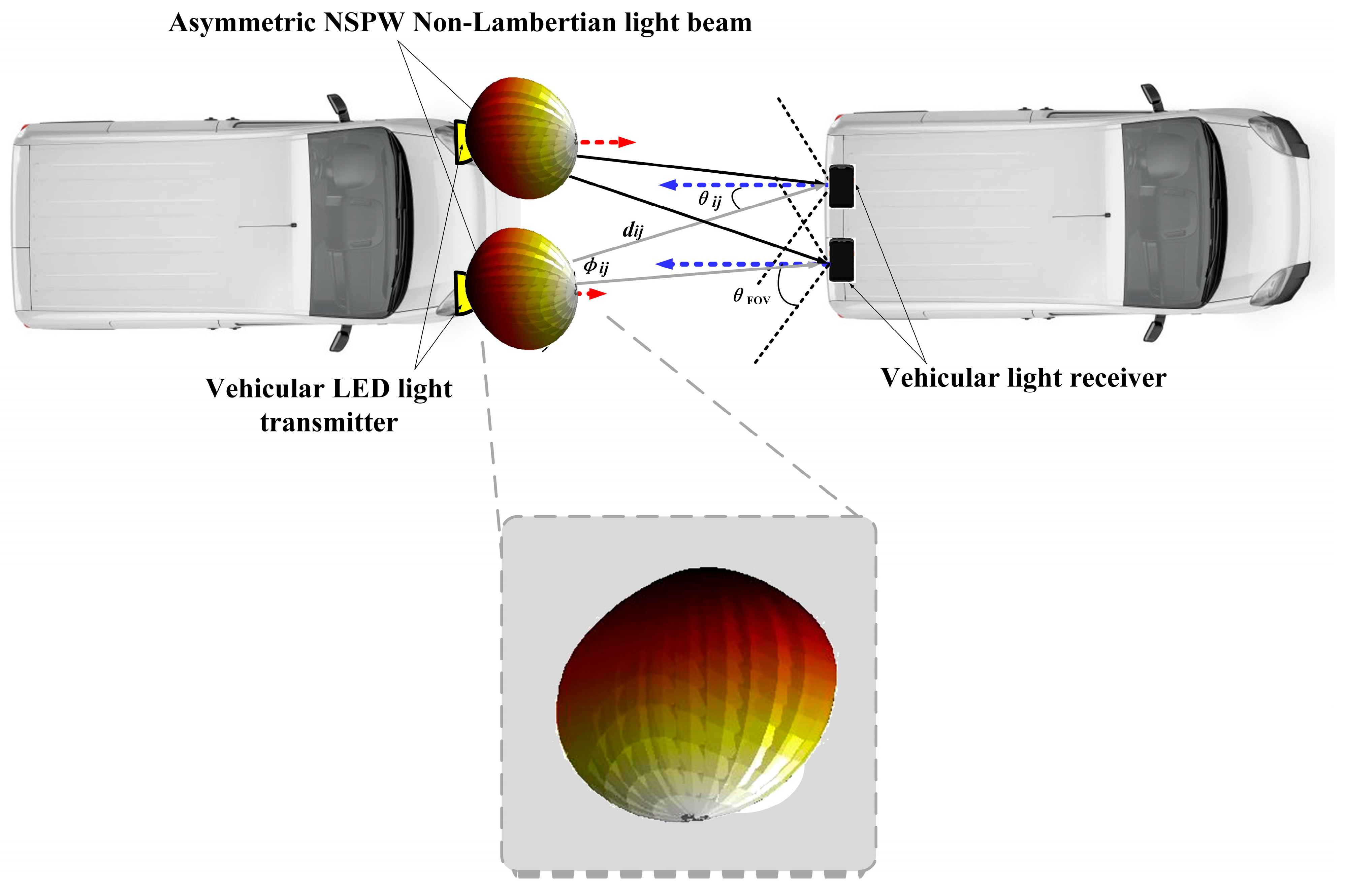
2.3. Vehicular MIMO Visible Light Communications Based on Asymmetric NSPW Non-Lambertian Light Beam Configuration

Particularly, for the case of vehicular MIMO VLC based on the left NSPW light beam, two headlamps also act as the distributed NSPW non-Lambertian light transmitters, and two photodiodes (PDs) located at the taillights to act as the light receivers, the output signal vector of the receiver is renewed by:
  y NSPW = H NSPW x + n ,
where y NSPW = [ y 1 NSPW , y 2 NSPW ]T are the received signal vector at the receiver of this NSPW non-Lambertian vehicular MIMO VLC system, H NSPW denotes the respective channel matrix based on the above NSPW non-Lambertian light beam configuration, which could be represented by:
  H NSPW = H 1 ,     1 NSPW H 1 ,     1 atm H 1 ,     2 NSPW H 1 ,     2 atm H 2 ,     1 NSPW H 2 ,     1 atm H 2 ,     2 NSPW H 2 ,     2 atm
where the element H i ,     j NSPW denotes the channel coefficient between the jth NSPW non-Lambertian LED transmitter and the ith PD receiver. Specifically, the system model (27) of this vehicular MIMO could be renewed by:
  y 1 NSPW y 2 NSPW = H 1 ,     1 NSPW H 1 ,     1 atm H 1 ,     2 NSPW H 1 ,     2 atm H 2 ,     1 NSPW H 2 ,     1 atm H 2 ,     2 NSPW H 2 ,     2 atm x 1 x 2 +   n 1 n 2 ,
Under such Z-Power non-Lambertian light beams configuration, the typical outdoor vehicular MIMO scenario is shown in Figure 3. Accordingly, the above light channel gain coefficient H i ,     j NSPW could be given by:
H i , j NSPW = R NSPW ( ϕ i , j , α i , j ) A PD P normNSPW d i , j 2 T s θ i , j g θ i , j cos θ i , j ,                   0 θ i , j θ FOV 0 ,                                                                                                                                         θ i , j > θ FOV ,
where P normNSPW denotes the power normalization factor of the NSPW light beam, which functions to ensure that the beam power radiated in all spatial directions is 1 W, while R NSPW ( ϕ i , j , α i , j ) denotes the NSPW non-Lambertian radiation intensity, which could be given by [22]:
R NSPW ( ϕ i , j , α i , j ) = l = 1 L g 11 NSPW exp In 2 ( ϕ i , j g 21 NSPW ) 2 cos 2 α i , j ( g 31 NSPW ) 2 + sin 2 α i , j ( g 41 NSPW ) 2 ,
where L = 2 is the amount of Gaussian functions. Specifically, the values of coefficients in this expression are g 11 NSPW = 0.13, g 21 NSPW = 45°, g 31 NSPW = g 41 NSPW = 18°, g 12 NSPW = 1, g 22 NSPW = 0, g 32 NSPW = 38° and g 42 NSPW = 22°. Unlike the previous Lambertian and the Z-Power non-Lambertian optical beam, the emission intensity of this NSPW non-Lambertian case is rotationally asymmetric. In addition, the respective 3D radiation pattern of the NSPW light beam is illustrated in Figure 3 as well. By substituting (5) and (31) into (30), the NSPW non-Lambertian light channel gain for this vehicular MIMO VLC could be explicitly renewed as:
H i , j NSPW = i = 1 2 g 1 i exp In 2 ( ϕ i , j g 2 i ) 2 cos 2 α i , j ( g 3 i ) 2 + sin 2 α i , j ( g 4 i ) 2   × A PD P normNSPW d i , j 2 T s θ i , j n 2 sin 2 θ FOV cos θ i , j , 0 θ i , j θ FOV 0 , θ i , j > θ FOV ,
Similarly, assuming equal power allocation, the channel capacity of this vehicular MIMO VLC system based on asymmetric NSPW non-Lambertian light beam could be given by:
C NSPW = log 2 det I M + E s N 0 N t 2 H NSPW H NSPW                 log 2 1 + E s N 0 N t 2 H NSPW 2 ,
At the same time, referring to (13), based on the channel coefficient under this rotational asymmetric NSPW non-Lambertian light beam configuration, the respective BER of RC MIMO mode should be renewed as:
BER RC NSPW 2 M 1 M log 2 M Q 1 M 1 E s N 0 N t 2 i = 1 N r j = 1 N t H i , j NSPW H i   , j atm 2 ,
Furthermore, by referring to (15), based on the channel coefficient under this rotational asymmetric NSPW non-Lambertian light beam configuration, the relevant end-to-end BER of SMP MIMO mode should be renewed as:
BER SMP NSPW 1 N t j = 1 N t 2 M j 1 M j log 2 M j Q 1 M j 1 E s N 0 N t 2 W j NSPW 2 ,
where W j NSPW denotes the jth row of pseudo-inverse of the channel matrix H NSPW , i.e., W NSPW which could be given by:
W NSPW = H NSPW T H NSPW 1 H NSPW T

3. Numerical Evaluation

In this section, the link characteristics comparison is made between the conventional Lambertian optical beam configuration and the emerging non-Lambertian optical beam configurations based on 6G MIMO vehicular visible light communications. Specifically, one typical outdoor inter-vehicular communications scenario within one lane is considered, which is consistent with Figure 1, Figure 2 and Figure 3. In addition, the main parameters of the MIMO inter-vehicular communication system are included in Table 1.
Without loss of generality, as for the baseline Lambertian optical beam, the Lambertian index is set as 1. In particular, following the work in [6], the vehicle width is set as 1.6 m for all concerned vehicles, while inter-vehicle distance is set as 2 m and 8 m for the stop mode and traffic mode, respectively. The emitted power of the transmitter is determined as 1 W and 10 W for the stop mode and traffic mode, accordingly. For the sake of simplicity, the optical filter gain is given as 1.

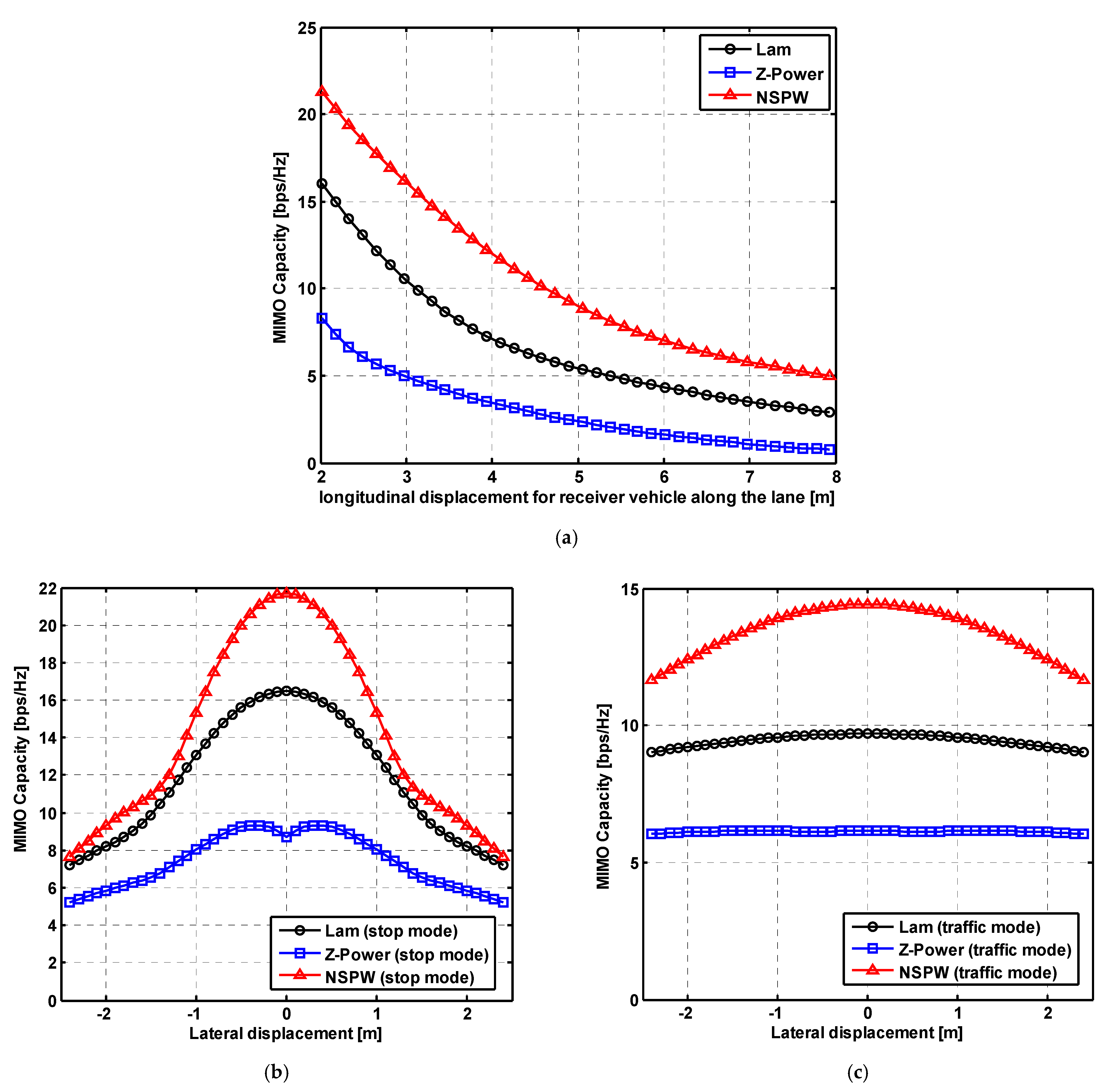
3.1. Effect of Longitudinal and Lateral Displacements

In this subsection, some numerical results are presented to quantify the effect of the longitudinal and lateral displacement on the inter-vehicle link performance of 6G MIMO vehicular VLC with different light beam configurations. Firstly, for the case of pure longitudinal displacement with the constant emitted power of 1 W, the MIMO channel capacity of vehicular visible light communications for distinct optical beam configurations is illustrated in Figure 4a. Specifically, when the longitudinal displacement gradually increased from the original 2 m to the final 8 m, for the baseline Lambertian light beam configuration, the respective channel capacity of MIMO vehicular VLC is reduced to about 2.89 bps/Hz from the initial about 16.04 bps/Hz; while the counterpart of the Z-power light beam is changed to about 0.75 bps/Hz from the initial about 8.30 bps/Hz. At the same time, the MIMO capacity of the NSPW light beam is similarly reduced to about 4.99 bps/Hz from the initial about 21.28 bps/Hz, which means that compared to the baseline Lambertian light beam configuration, the MIMO capacity gain provided by the non-Lambertian NSPW light beam is gradually reduced to about 2.10 bps/Hz from the initial about 5.24 bps/Hz, once the longitudinal displacement for receiver vehicle along the lane is increased to the 8 m from the initial 2 m.
In addition, the MIMO channel capacity of vehicular visible light communications with different lateral displacements for receiver vehicles in stop mode and traffic mode is illustrated in Figure 4b,c separately. Apparently, the MIMO channel capacity presents obvious symmetry around the centerline of 0 lateral displacement within the lane. In stop mode with emitted power of 1 W, once the lateral displacement for receiver vehicle is gradually increased to about 2.5 m, the MIMO channel capacity of the Lambertian light beam configuration is reduced to about 7.24 bps/Hz from the initial about 16.49 bps/Hz, while the counterpart of the non-Lambertian Z-power light beam is changed to 5.24 bps/Hz from the initial about 8.72 bps/Hz, which the MIMO capacity loss is reduced to about 2 bps/Hz from the initial about 7.77 bps/Hz compared to the performance of the baseline Lambertian beam configuration. As for the case of novel the non-Lambertian NSPW light beam, the MIMO capacity is intensively reduced to about 7.67 bps/Hz from the initial about 21.68 bps/Hz, which indicates that MIMO capacity gain is reduced to about 0.43 bps/Hz from the initial about 5.19 bps/Hz compared to the performance metric of the baseline Lambertian beam configuration. Moreover, in the traffic mode with an emitted power of 10 W, the phenomena of similar MIMO channel capacity reduction could be observed in Figure 4c for all concerned light beam configurations. In particular, with the lateral displacement gradually increased to about 2.5 m, the MIMO capacity is reduced to about 9.03 bps/Hz from the initial about 9.70 bps/Hz for Lambertian light beam configuration to about 6.04 bps/Hz from the initial about 6.17 bps/Hz for Z-power non-Lambertian light beam configuration, and to about 11.65 bps/Hz from the initial about 14.41 bps/Hz for NSPW non-Lambertian light beam configuration, which means that in traffic mode, the MIMO capacity performance is less sensitive to the lateral displacement for the receiver vehicle.

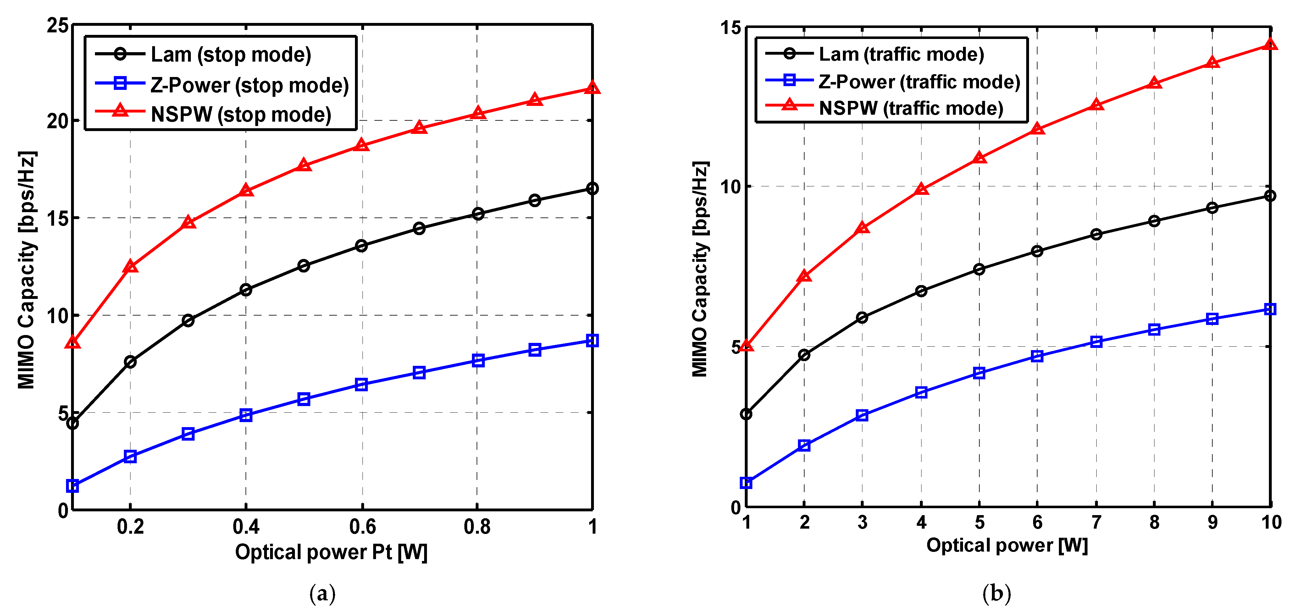
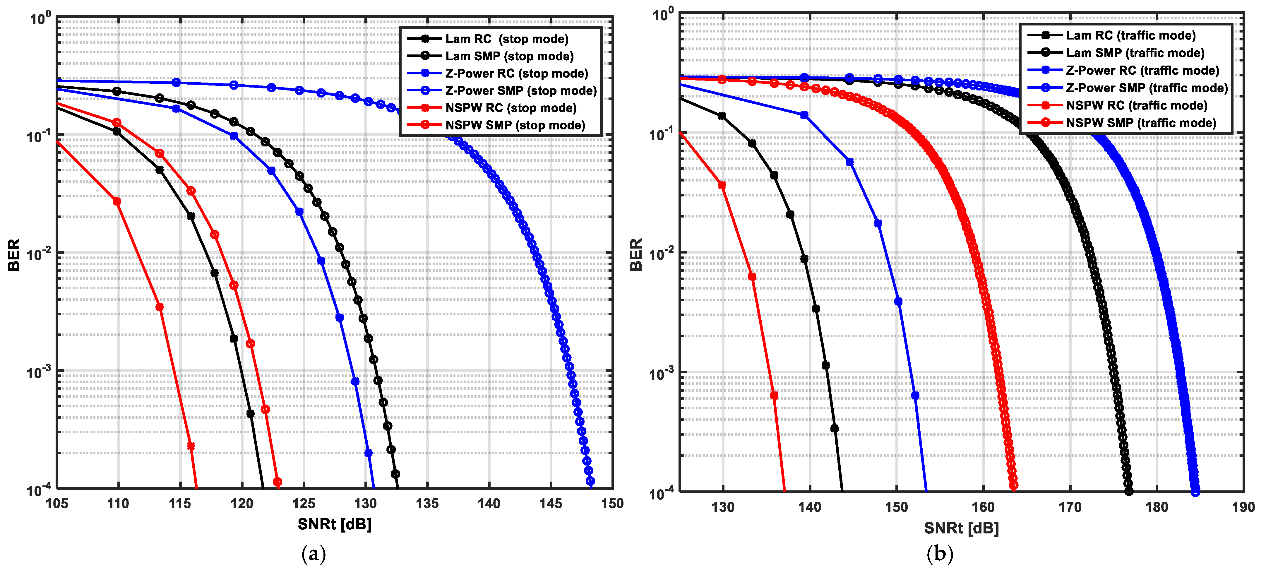
3.2. Effect of Emitted Power

For investigating the effect of emitted power on the performance of the MIMO channel capacity of vehicular visible light communications, different emitted optical power are introduced to the three inter-vehicle MIMO VLC systems with distinct light beam configurations in outdoor lane environments, as shown in Figure 5. For the case of stop mode, when the emitted optical power is increased to 1 W from the initial 0.1 W, MIMO channel capacity is increased to 16.50 bps/Hz from the initial 4.40 bps/Hz to 8.72 bps/Hz from the initial 1.22 bps/Hz, and to 21.68 bps/Hz from the initial 8.57 bps/Hz for the baseline Lambertian beam configuration, the non-Lambertian Z-power light beam configuration, and the non-Lambertian NSPW light beam configuration, separately. Therefore, the MIMO channel capacity gain induced by the NSPW beam configuration is accordingly enhanced to 5.18 bps/Hz from the initial 4.17 bps/Hz, compared with the baseline Lambertian beam configuration.
Similarly, for the case of traffic mode, when the emitted optical power is increased to 10 W from the initial 1 W, MIMO channel capacity is increased to 9.70 bps/Hz from the initial 2.88 bps/Hz to 6.17 bps/Hz from the initial 0.744 bps/Hz, and to 14.41 bps/Hz from the initial 4.98 bps/Hz for the baseline Lambertian beam configuration, the non-Lambertian Z-power light beam configuration, and the non-Lambertian NSPW light beam configuration, separately. Therefore, the MIMO channel capacity gain induced by the NSPW beam configuration is accordingly enhanced to 4.71 bps/Hz from the initial 2.10 bps/Hz, compared with the baseline Lambertian beam configuration.
Furthermore, the BER performance of MIMO vehicular visible light communications for 6G IoV versus the emitted power of the transmitter is investigated as well. In stop mode with RC MIMO, to achieve BER of 10−4, the required transmitted signal-to-noise ratio (SNRt) is about 121 dB, about 131 dB, and about 116 dB for the baseline Lambertian beam configuration, the non-Lambertian Z-power light beam configuration, and the non-Lambertian NSPW light beam configuration, separately, which means the SNRt saving, in other words SNRt gain is about 5 dB achieved by the introducing the novel NSPW light beam configuration, compared with the counterpart of the baseline Lambertian beam configuration, as shown in Figure 6a. Similarly, for the SMP MIMO, to achieve BER of 10−4, the required transmitted signal-to-noise ratio (SNRt) is about 132 dB, about 148 dB, and about 123 dB for the baseline Lambertian beam configuration, the non-Lambertian Z-power light beam configuration, and the non-Lambertian NSPW light beam configuration, separately, which means the SNRt gain is about 9 dB achieved by the introducing the novel NSPW light beam configuration, compared with the counterpart of the baseline Lambertian beam configuration, as shown in Figure 6a.
As for the more challenging traffic mode, more emitted power is needed to achieve the same target BER performance, which is independent of the light beam configurations, since the inter-vehicle distance is increased to 8 m from the initial 2 m of the stop mode. Particularly, in traffic mode with RC MIMO, to achieve BER of 10−4, the required SNRt is about 143 dB, about 153 dB, and about 137 dB for the baseline Lambertian beam configuration, the non-Lambertian Z-power light beam configuration, and the non-Lambertian NSPW light beam configuration, separately, which means the SNRt gain is about 6 dB achieved by the introducing the novel NSPW light beam configuration, compared with the counterpart of the baseline Lambertian beam configuration, as shown in Figure 6b. Similarly, for the SMP MIMO in traffic mode, to achieve BER of 10−4, the required transmitted signal-to-noise ratio (SNRt) is about 177 dB, about 184 dB, and about 163 dB for the baseline Lambertian beam configuration, the non-Lambertian Z-power light beam configuration, and the non-Lambertian NSPW light beam configuration, separately, which means the SNRt gain is about 14 dB achieved by the introducing the novel NSPW light beam configuration, compared with the counterpart of the baseline Lambertian beam configuration, as shown in Figure 6b.

3.3. Effect of Receiver Spacing

For investigating the effect of receiver spacing on the performance of MIMO vehicular visible light communications for 6G IoV, different receiver PD spacing settings between 0.1 m and 1.2 m are introduced to the three inter-vehicle MIMO VLC systems with distinct light beam configurations in typical outdoor lane environments, as shown in Figure 7.
For the case of stop mode, the MIMO channel capacity is about 11.17 bps/Hz, 7.45 bps/Hz, and 15.66 bps/Hz for the baseline Lambertian light beam configuration, Z-power non-Lambertian light beam configuration and NSPW non-Lambertian light beam configuration with the initial PD spacing of 0.1 m. With this PD spacing further increased to 1.2 m, the MIMO channel capacity is gradually enhanced to about 16.49 bps/Hz, 8.72 bps/Hz, and 21.68 bps/Hz for the mentioned three beam configurations. Accordingly, compared with the baseline performance of the well-known Lambertian light beam, the MIMO capacity gain brought by the NSPW non-Lambertian light beam is lightly varied to 5.19 bps/Hz from the original 4.49 bps/Hz, as shown in Figure 7a.
Furthermore, for the case of more challenging traffic mode, the MIMO channel capacity is about 9.34 bps/Hz, 6.13 bps/Hz, and 11.61 bps/Hz for the baseline Lambertian light beam configuration, Z-power non-Lambertian light beam configuration and NSPW non-Lambertian light beam configuration with the initial PD spacing of 0.1 m. With this PD spacing further increased to 1.2 m, the MIMO channel capacity is gradually changed to about 9.70 bps/Hz, 6.17 bps/Hz, and 14.41 bps/Hz for the mentioned three beam configurations. Accordingly, compared with the baseline performance of the well-known Lambertian light beam, the capacity gain brought by the NSPW light beam is apparently varied to 4.71 bps/Hz from the original 2.27 bps/Hz, as shown in Figure 7b.

4. Conclusions

This work is motivated by the limitation of the conventional MIMO vehicular visible light communications research paradigm based on the well-discussed Lambertian optical beam, which could not address the investigations of MIMO vehicular visible light communications based on emerging non-Lambertian optical beams. In this work, the commercially available non-Lambertian sources are introduced to configure the MIMO vehicular transmitter, and the relevant vehicular link characteristics performance is numerically evaluated for future 6G internet of vehicles environment. For the concerned non-Lambertian vehicles MIMO configuration, for achieving the target BER of 10−4 under non-Lambertian NSPW vehicles MIMO configuration, the required transmitted SNR is about 123 dB, while the counterpart of the baseline Lambertian vehicle MIMO configuration is about 132 dB accordingly, and up to about 9 dB gain could be provided by the novel non-Lambertian configuration. In future work, the exploration of non-Lambertian vehicles MIMO will be extended to vehicle beam switching, vehicle beam combination, vehicle dynamic beam configuration, vehicle resource allocation, and other enabling techniques design. Moreover, we will push the relevant experimental work forward to illustrate the vehicle’s MIMO coverage with distinct optical beam configurations.

Author Contributions

J.D., Determine the theme and structure of the article, provide professional knowledge in the field of visible light communications, write and modify the article, and reply to comments from editors and reviewers; C.-L.I., Provide theoretical knowledge of mobile communication and wireless communication; J.W., Find the literature, participate in the discussion and writing some of the content; H.Y., Looking for literature, participate in the discussion and writing some of the content. All authors have read and agreed to the published version of the manuscript.

Funding

This work was supported in part by the National Natural Science Foundation of China (Grants No. 62061043), the Tianshan Cedar Project of Xinjiang Uygur Autonomous Region (Grants No. 2020XS27), and High-level Talents Introduction Project in Autonomous Region (Grants No. 042419004).

Data Availability Statement

Data are contained within the article.

Conflicts of Interest

The authors declare no conflicts of interest.

References

  1. Refas, S. Performance Analysis of Bidirectional Multi-Hop Vehicle-to-Vehicle Visible Light Communication. IEEE Access 2023, 11, 129436–129448. [Google Scholar] [CrossRef]
  2. Yahia, S.; Meraihi, Y.; Ramdane-Cherif, A.; Ho, T.D.; Eldeeb, H.B. Enhancement of Vehicular Visible Light Communication Using Spherical Detector and Custom Lens Combinations. IEEE Access 2023, 11, 21600–21611. [Google Scholar] [CrossRef]
  3. Meghraoui, A. Is Visible Light Communications Suitable for Using in Lane-Changing Maneuvers. In Proceedings of the 2023 International Conference on Advanced Technologies for Communications (ATC), Da Nang, Vietnam, 19–20 October 2023; IEEE: New York, NY, USA, 2023. [Google Scholar]
  4. Ullah, A.; Choi, W.; Coleri, S. Path Loss Estimation and Jamming Detection in Hybrid RF-VLC Vehicular Networks: A Machine-Learning Framework. IEEE Sens. J. 2023, 23, 31325–31336. [Google Scholar] [CrossRef]
  5. Haas, H. Introduction to indoor networking concepts and challenges in LiFi. J. Opt. Commun. Netw. 2020, 12, A190–A203. [Google Scholar] [CrossRef]
  6. Shaaban, R.; Faruque, S. Cyber security vulnerabilities for outdoor vehicular visible light communication in secure platoon network: Review, power distribution, and signal to noise ratio analysis. Phys. Commun. 2020, 40, 101094. [Google Scholar] [CrossRef]
  7. Zhang, Y.; Wang, Y.; Deng, Y.; Du, A.; Liu, J. Design of a Free Space Optical Communication System for an Unmanned Aerial Vehicle Command and Control Link. Photonics 2021, 8, 163. [Google Scholar] [CrossRef]
  8. Chowdhury, M.Z.; Hasan, M.K.; Shahjalal, M.; Hossan, M.T.; Jang, Y.M. Optical wireless hybrid networks: Trends, opportunities, challenges, and research directions. IEEE Commun. Surv. Tutor. 2020, 22, 930–966. [Google Scholar] [CrossRef]
  9. Saikrishnan, S.; Singh, P.; Singh, A.; Srivastava, A. Hybrid RF-VLC Technology for V2X in Platooning Applications Under Different Weather Conditions. In Proceedings of the 2024 IEEE Wireless Communications and Networking Conference (WCNC), Dubai, United Arab Emirates, 4–7 September 2024; IEEE: New York, NY, USA, 2024. [Google Scholar]
  10. Deng, P.; Kavehrad, M. Adaptive real-time software defined MIMO visible light communications using spatial multiplexing and spatial diversity. In Proceedings of the 2016 IEEE International Conference on Wireless for Space and Extreme Environments (WiSEE), Aachen, Germany, 23–25 June 2016; IEEE: New York, NY, USA, 2016. [Google Scholar]
  11. Mmbaga, P.F.; Thompson, J.; Haas, H. Performance Analysis of Indoor Diffuse VLC MIMO Channels Using Angular Diversity Detectors. J. Light. Technol. 2016, 34, 1254–1266. [Google Scholar] [CrossRef]
  12. Sejan, M.A.S.; Rahman, M.H.; Aziz, M.A.; Kim, D.-S.; You, Y.-H.; Song, H.-K. A Comprehensive Survey on MIMO Visible Light Communication: Current Research, Machine Learning and Future Trends. Sensors 2023, 23, 739. [Google Scholar] [CrossRef] [PubMed]
  13. Liu, W.; He, X. Performance Analysis of MIMO Visible Light Based V2V Communications. In Proceedings of the 2019 IEEE 89th Vehicular Technology Conference (VTC2019-Spring) , Kuala Lumpur, Malaysia, 28 April–1 May 2019; IEEE: New York, NY, USA, 2019. [Google Scholar]
  14. Li, G.; Niu, W.; Ha, Y.; Hu, F.; Wang, J.; Yu, X.; Chi, N. Position-Dependent MIMO Demultiplexing Strategy for High-Speed Visible Light Communication in Internet of Vehicles. IEEE Internet Things J. 2022, 9, 10833–10850. [Google Scholar] [CrossRef]
  15. Farahneh, H.; Hussain, F.; Hussain, R.; Fernando, X. A Novel Optimal Precoder and Equalizer in 2 × 2 MIMO VLC Systems for Vehicular Application. In Proceedings of the 2018 IEEE Globecom Workshops (GC Wkshps), Abu Dhabi, United Arab Emirates, 9–13 December 2018; IEEE: New York, NY, USA, 2018. [Google Scholar]
  16. Okasha, N.M.; Zekry, A.H.A.; Newagy, F.A. Developing hybrid car-to-car communication system based on MIMO visible light and radio frequency. J. Wirel. Com Netw. 2022, 114, 1–19. [Google Scholar] [CrossRef]
  17. Mansour, I.M.; Farahneh, H. Comparison of Various Detection Algorithms in a 2 × 2 MIMO VLC Systems for Vehicular Application. In Proceedings of the 2023 2nd International Engineering Conference on Electrical, Energy, and Artificial Intelligence (EICEEAI), Zarqa, Jordan, 27–28 December 2023; IEEE: New York, NY, USA, 2023. [Google Scholar]
  18. Jia, J.; Zou, P.; Hu, F.; Zhao, Y.; Chi, N. Flexible Data Rate V2X Communication System beyond 1.84 Gb/s Based on MIMO VLC and Radar Integration. Appl. Sci. 2020, 10, 6636. [Google Scholar] [CrossRef]
  19. Azizi, M.; Zeinali, F.; Mili, M.R.; Shokrollahi, S. Efficient AoI-Aware Resource Management in VLC-V2X Networks via Multi-Agent RL Mechanism. IEEE Trans. Veh. Technol. 2024, 73, 14009–14014. [Google Scholar] [CrossRef]
  20. Ding, J.; I, C.-L.; Wang, J.; Song, J. Coverage Performance of Non-Lambertian Underwater Wireless Optical Communications for 6G Internet of Things. Inventions 2024, 9, 49. [Google Scholar] [CrossRef]
  21. Kumar, A.; Ghorai, S.K. Effect of LED Radiation Pattern on BER Performance in Indoor Multipath MIMO-VLC System. Wirel. Pers. Commun. 2020, 113, 2009–2026. [Google Scholar] [CrossRef]
  22. Moreno, I.; Sun, C.-C. Modeling the radiation pattern of LEDs. Opt. Exp. 2008, 16, 1808–1819. [Google Scholar] [CrossRef] [PubMed]
  23. Nakagawa, M. Fundamental analysis for visible-light communication system using LED lights. IEEE Trans. Consum. Electron. 2004, 50, 100–107. [Google Scholar]
  24. Ding, J.; Chih-Lin, I.; Xu, Z. Indoor optical wireless channel characteristics with distinct source radiation patterns. IEEE Photonics J. 2016, 8, 1–15. [Google Scholar] [CrossRef]
Figure 1. Schematic of vehicular MIMO visible light communications based on baseline Lambertian light beam for 6G internet of vehicles.
Inventions 10 00001 g001
Figure 2. Schematic of vehicular MIMO visible light communications based on Z-Power light beam for 6G internet of vehicles.
Inventions 10 00001 g002
Figure 3. Schematic of vehicular MIMO visible light communications based on asymmetric NSPW non-Lambertian light beam for 6G internet of vehicles.
Inventions 10 00001 g003
Figure 4. MIMO channel capacity of vehicular visible light communications for 6G IoV in the case of (a) different longitudinal displacement for receiver vehicle along the lane, (b) different lateral displacement for receiver vehicle in stop mode, (c) different lateral displacement for receiver vehicle in traffic mode.
Inventions 10 00001 g004
Figure 5. MIMO channel capacity of vehicular visible light communications for 6G IoV versus the emitted power of the transmitter in the case of (a) stop mode and (b) traffic mode.
Inventions 10 00001 g005
Figure 6. BER performance of MIMO vehicular visible light communications for 6G IoV versus the emitted power of the transmitter in the case of (a) stop mode and (b) traffic mode.
Inventions 10 00001 g006
Figure 7. MIMO channel capacity of vehicular visible light communications for 6G IoV versus the receiver spacing in the case of (a) stop mode and (b) traffic mode.
Inventions 10 00001 g007
Table 1. Main parameters configuration.
ParametersValues
Hight of transmitters0.8 m
Spacing of transmitters1.20 m
Number of transmitters2
Emitted optical power of transmitters1 W (stop mode), 10 W (traffic mode)
LED Lambertian index1
Receiver field of view90°
Hight of receiving plane0.8 m
Type of photodiodePIN PD
Physical area of PD1.0 cm2
Responsively of PD0.28 A/W
Concentrator refractive index1.54
Optical filter gain1
Spacing of receivers1.20 m
Number of transmitters2
ChannelLOS
Meteorological visibility0.50 km
ModulationM-PAM
Modulation bandwidth20 MHz
Disclaimer/Publisher’s Note: The statements, opinions and data contained in all publications are solely those of the individual author(s) and contributor(s) and not of MDPI and/or the editor(s). MDPI and/or the editor(s) disclaim responsibility for any injury to people or property resulting from any ideas, methods, instructions or products referred to in the content.

