Article

Modeling and Stability Analysis of Hybrid PV/Diesel/ESS in Ship Power System

1
College of Automation, Harbin Engineering University, Harbin 150001, China
2
Department of Electrical Engineering and Computer Science, University of Wisconsin-Milwaukee, Milwaukee, WI 53211, USA
3
Department of Electrical Engineering, Chung Yuan Christian University, Chung Li 32023, Taiwan
*
Author to whom correspondence should be addressed.
Inventions 2016, 1(1), 5; https://doi.org/10.3390/inventions1010005
Submission received: 23 January 2016 / Revised: 29 February 2016 / Accepted: 3 March 2016 / Published: 9 March 2016
(This article belongs to the Special Issue New Technologies for Maritime Power Systems)

Abstract

:
Due the concern about serious environmental pollution and fossil energy consumption, introducing solar generation into ship power systems has drawn greater attention. However, the penetration of solar energy will result in ship power system instability caused by the uncertainties of the solar irradiation. Unlike on land, the power generated by photovoltaic (PV) modules on the shipboard changes as the ship rolls. In this paper, a high-speed flywheel energy storage system (FESS) is modeled to smooth the PV power fluctuations and improve the power quality on a large oil tanker which contains a PV generation system, a diesel generator, a FESS, and various types of ship loads. Furthermore, constant torque angle control method combined with sinusoidal pulse width modulation (SPWM) approach is proposed to control the FESS charging and discharging. Different ship operating situations and the impact of the ship rolling is taken into consideration. The simulation results demonstrate the high efficiency and fast response of the flywheel energy storage system to enhance the stability of the proposed hybrid ship power system.

1. Introduction

Owing to the ever increasing amount of greenhouse gas and the consumption of fossil energy by ship systems, strict restrictions have recently been imposed by the International Convention for the Prevention of Pollution from Ships (MARPOL) [1] to limit the collective emissions of greenhouse gas produced by ships. The application of solar energy in ship power system provides a new way to reduce emissions, improve energy efficiency and enhance ship power system stability [2]. With the rapid development of renewable energy, photovoltaic (PV) generation systems have drawn more attention in many areas [3,4,5,6]. However, a high penetration of solar energy will result in a risk of frequency stability and an increase of undesired power cost caused by the uncertainty of the solar irradiation. According to the previous studies [7,8,9,10], the utilization of an energy storage system (ESS) is one of the best solutions for ensuring the reliability and power quality of power systems and favors the increased penetration of distributed generation resources. Compared with the flexibility of the diesel generator and natural gas turbine, an energy storage system is easier to install to enhance the stability of the power system, especially in a microgrid.
Among various types of ESSs, a FESS has many advantages, as follows:
  • high energy density and long working lifecycle;
  • fast response to smooth the frequency fluctuations;
  • high efficiency with a lower loss;
  • flexible for an application as a decentralized power supply unit;
  • wide operating temperature range, and so on.
The FESS stores mechanical energy in a rotating flywheel and this energy can be converted back to the electrical energy by means of an electrical machine [11]. Similarly, the the flywheel transforms the electrical energy into mechanical energy through versa the electrical machine. FESSs are suitable for numerous charge and discharge cycles (hundred of thousands), which are used for the short-time application (seconds to minutes) in medium to high power systems (kW to MW). Compared with the ultracapacitor and superconducting magnetic energy storage technologies, FESSs have a higher energy density and efficiency.
Recently, a wide range of investigations [12,13,14,15,16,17,18] have been performed regarding the application of FESSs. In [12], the authors analyzed a hybrid energy system performance with PV modules and diesel systems as well as an ESS, and the FESS is equipped to store excess energy from the PV generation system. The research in [13,14] developed a FESS model to smooth the power fluctuations of a wind energy conversion system, and a comparison without energy storage-based power smoothing methods was also conducted. A global supervisory strategy for a micro-grid power generation system that comprises wind generation systems, PV generation systems, and FESS, a flywheel storage system, was proposed in [15] to reduce energy costs and greenhouse gas emissions and to extend the life of the flywheel. A FESS based on a doubly-fed induction machine was utilized in [16] to supply an exponentially decaying current to the grid during the fault. Studies in [17] and [18] established a detailed FESS model for vehicular applications in order to meet the societal demand and ecological need for clean transportation.
To the best of the authors’ knowledge, the hybrid PV/diesel/ESS ship power system has not been extensively discussed [19,20,21]. The optimal size of a hybrid PV/diesel/battery ship power system was presented in [19] but the impact of ship roll is not taken into account. The research in [20] explored a fuel cell power plant for small ships and underwater vehicles. In [21], a hybrid PV/diesel green ship was discussed but the research was only in the experimental stage. In this paper, a hybrid PV/diesel/FESS ship power system is set up based on the project “Study on the Application of Photovoltaic Technology in the Oil Tanker Ship” in China [22]. Unlike a PV system on land, a shipboard PV system is changing at all times with the ship rolling even though the magnitude of solar irradiation is fixed. Therefore, a high-speed flywheel energy storage system is modeled for smoothing the fluctuations generated by a shipboard PV system, including a permanent magnet synchronous motor (PMSM) and a bidirectional converter. Furthermore, in order to achieve a fast response to mitigate the influence of ship rolling, a constant torque angle control strategy is employed for FESS charging and discharging. In addition, various types of ship loads are considered.
The rest of this paper is organized as follows: Section 2 presents the configuration and mathematical model of the hybrid ship power system. Section 3 proposes the control strategy. Section 4 analyzes the stability of the hybrid ship power system and Section 5 draws conclusions.

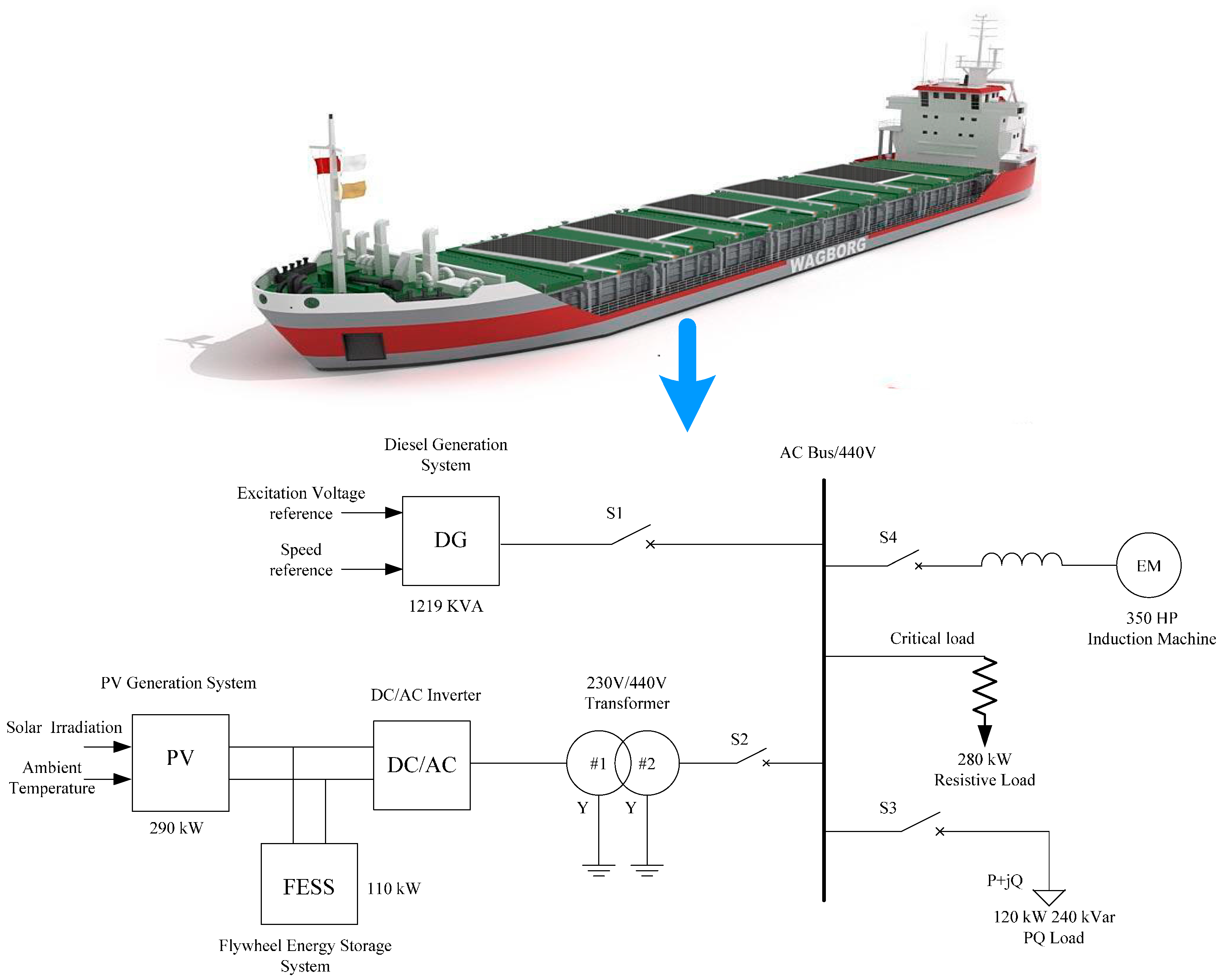
2. Hybrid Ship Power System Configuration and Components

2.1. Hybrid Ship Power System Structure

The focus of this work is to analyze the behavior and stability of a hybrid PV/diesel/ESS system on a large oil tanker ship which is based on the project named “Study on the Application of Photovoltaic Technology in the Oil Tanker Ship” [22]. The detailed parameters of this oil tanker are that the length, width, and height are 332.95, 60.00 and 30.50 m, respectively. The deadweight of this oil tanker is 100,000 tons. Additionally, the system, with a scale of 440V and 60 Hz consisting of one 290 kW PV generation system, one 1219 kVA diesel generator and one 110 kW FESS is shown in Figure 1.

2.2. Models of System Components

2.2.1. PV Generation System

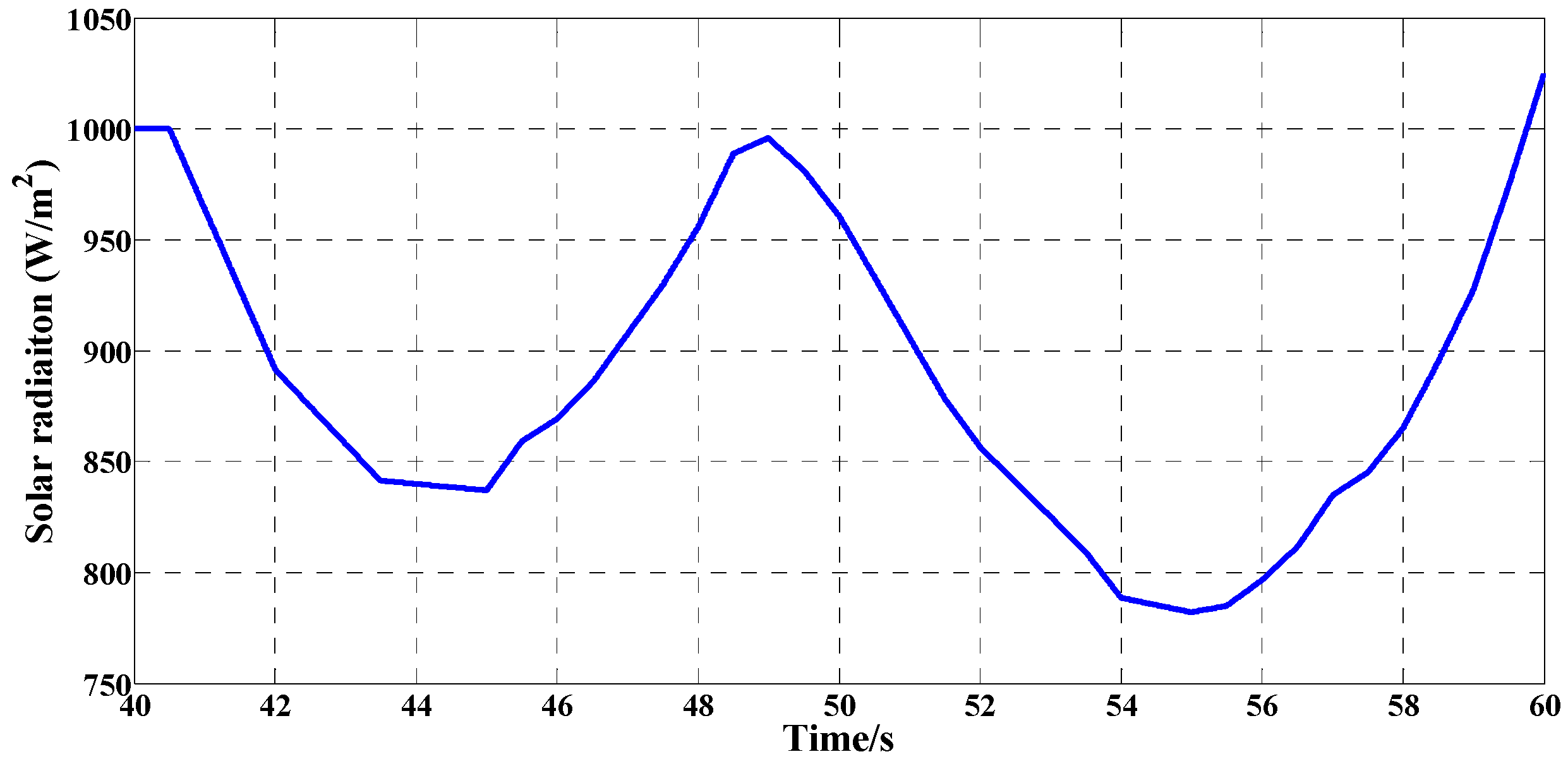
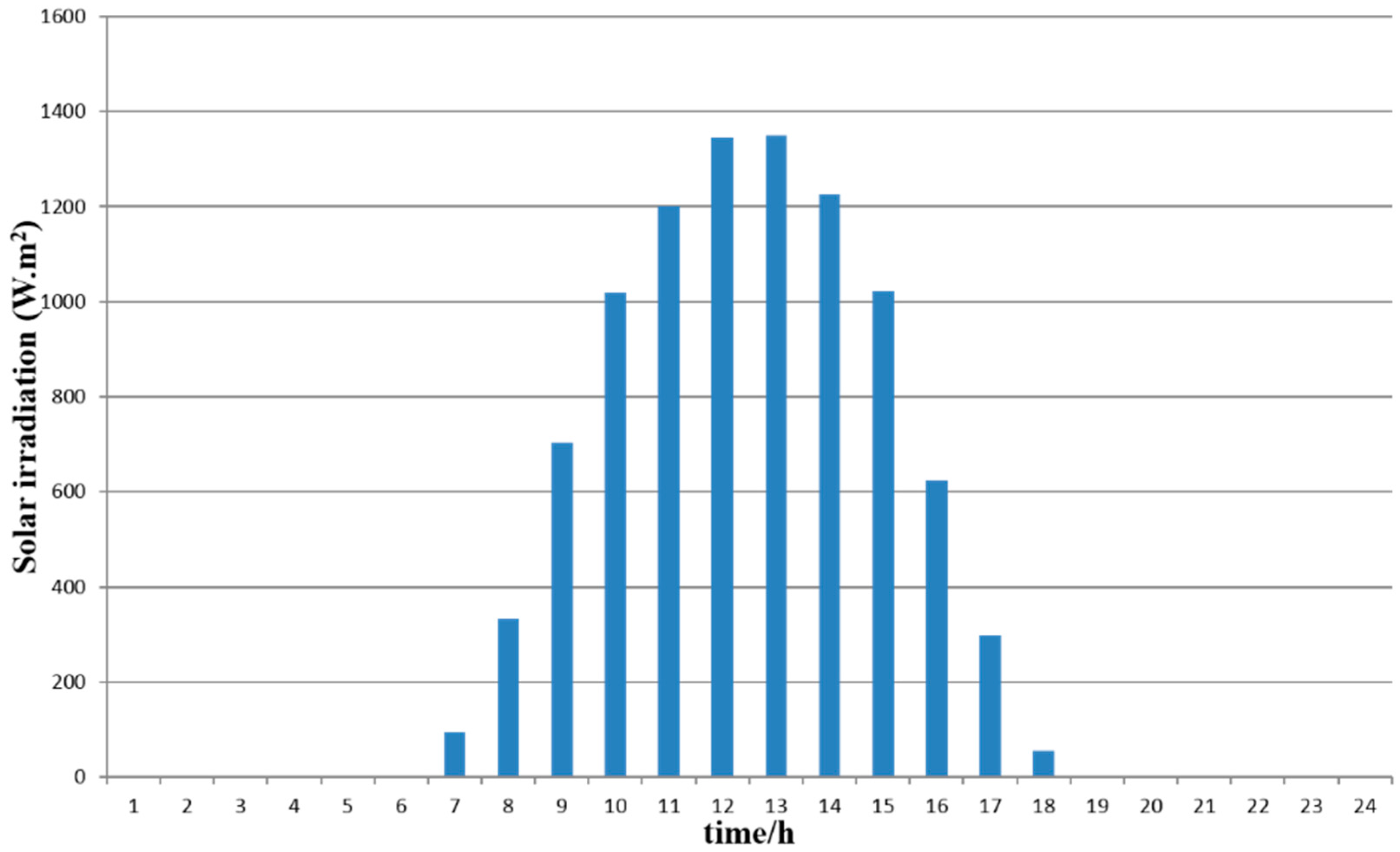
(1) Solar Irradiation Simulation
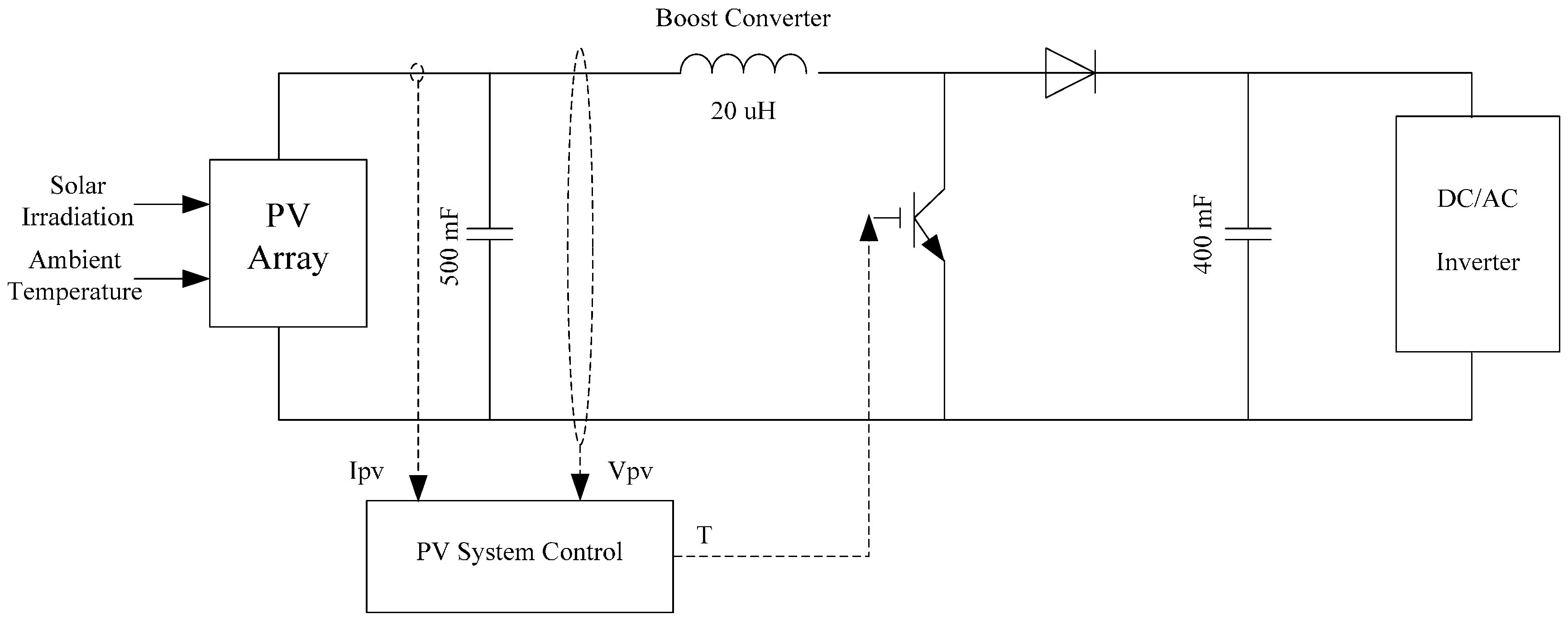
Unlike PV system on land, the output power produced by shipboard PV modules varies with the ship rolling even though the magnitude of solar irradiation is fixed. Consequently, a dynamic model for solar irradiation is built considering the impact of the ship rolling and Figure 2 shows the solar irradiation received by PV panels on a large oil tanker ship.
Due to the typical navigation route for this oil tanker ship from Dalian in China to Aden in Yemen, the maximum angle for the ship rolling is 16 degrees when the ship sails in the ocean. A worst case with a 20 s rolling period and 16-degree rolling angle is selected to perform case study.

(2) PV Model

As the only renewable energy featured in the hybrid ship power system, the PV generation system plays an essential role in reducing the CO2 emissions [23], so a detailed PV model with maximum power point tracing control method is developed in the paper. The PV generation consists of 2000 PV panels with the rated power of 290 kW, a boost converter and a bidirectional converter. The structure of the PV model is described in Figure 3.

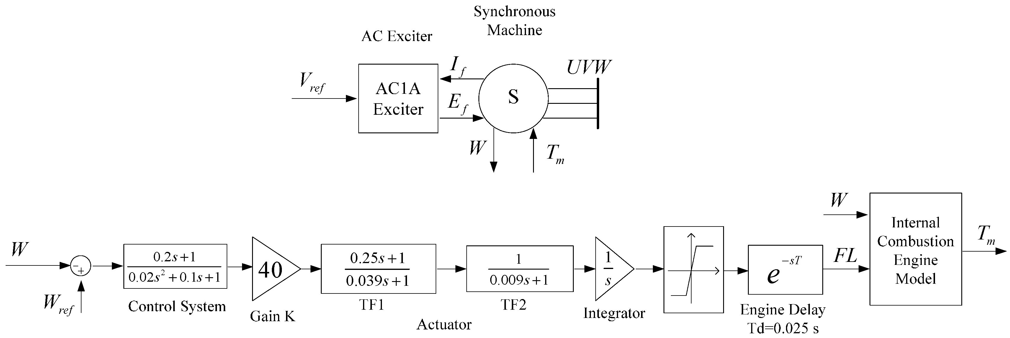
2.2.2. Diesel Generator

As a main electrical energy source in a hybrid ship power system, a diesel generator [24] is used to maintain the whole system’s voltage and meet the load demand in case the total power generated by both the PV modules and the ESS is insufficient. In this paper, a 1219 kVA synchronous diesel generation system is established and a governor control is implemented to regulate the speed of the generator. The detail diesel generator model, which consists of an exciter system, a synchronous generator, and a diesel internal combustion engine, is shown in Figure 4. It should be noted that the diesel generator must be able to supply the whole load all the time because the ship’s power system always operates in stand-alone mode, which is different from power systems on land.

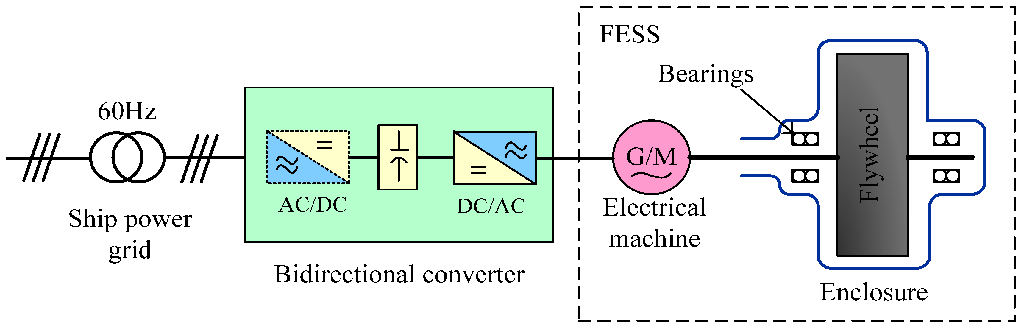
2.2.3. Flywheel Energy Storage System
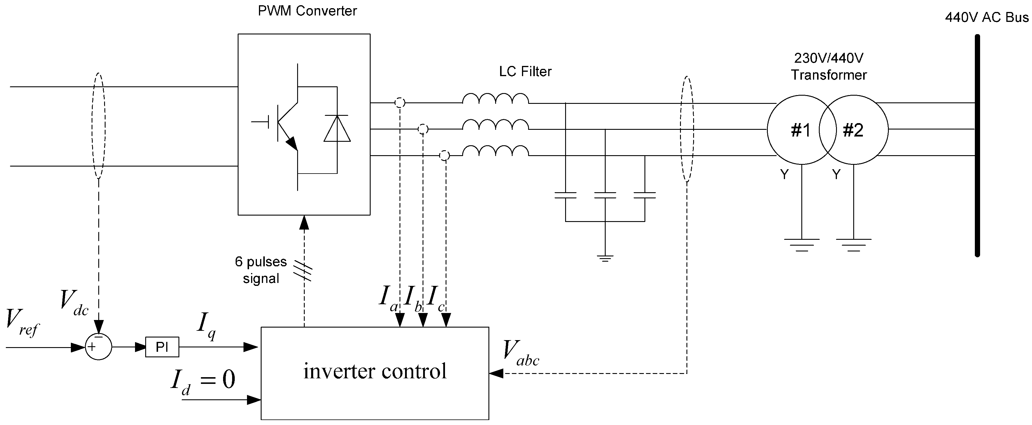
A flywheel energy storage system (FESS) is a power storage device that stores or releases electrical power as rotational energy [25]. When energy is extracted from the system, the speed of the rotor (flywheel) is reduced as a consequence of the principle of conservation of energy, and adding energy to the system correspondingly results in a rise of the speed of the flywheel. More specifically, the energy E stored in a high-speed flywheel is given by:
E = 1 2 J ω 2
where J = r 2 d m denotes the moment of inertia of flywheel rotor (kg*m2); ω is the angular speed of flywheel (rad/s).
In this paper, a high-speed FESS is modeled to smooth the power fluctuations generated by PV modules and to improve the energy efficiency of the hybrid ship power system. The structure of the proposed FESS is displayed in Figure 5.
The proposed FESS comprises a flywheel, bearings, permanent magnet synchronous machine (PMSM), and a bidirectional power converter associated with a capacity of 110 kW. Furthermore, due to the important role of PMSM, a mathematical model related to Eqations 2–4 is established in detail for further advanced control strategy to manage the state of charge (SOC) of FESS effectively.
Stator voltage equation   { u s d = R s i s d + d ψ s d d t ω r ψ s q u s q = R s i s q + d ψ s q d t + ω r ψ s d
Stator flux linkage equation     { ψ s d = L d i s d + ψ f ψ s q = L q i s q
Electromagnetic torque equation     T e = 3 2 n p ( ψ s d i s q ψ s q i s d )
where u s d and u s q denote the direct-axis and quadrature-axis voltage of stator winding(V); i s d and i s q denote the direct-axis and quadrature-axis current of stator winding (A); ψ s d and ψ s q denote the direct-axis and quadrature-axis flux linkage of stator winding (Wb); L d and L q denote the direct-axis and quadrature-axis inductance of stator winding (H); ω r is the angular speed of rotor (rad/s); R s is the resistance of stator (Ω); ψ f is the flux linkage of rotor (Wb); n p is the pole pairs; and T e is the electromagnetic torque of rotor (N·m).

2.2.4. Converter

The main circuit of the grid-connected converter is detailed in Figure 6, and consists of a three-phase full-bridge circuit, a LC filter and control block. The DC voltage is controlled and maintained at Vref, which is set to 410 V.

2.2.5. Loads

The characteristics of the load profile are critical in stability analysis of a hybrid ship power system. This paper presents three different types of ship loads which are equivalent asynchronous motors, the resistive load and the reactive load with respect to 350 HP, 400 kW and 240 kVar, separately. The variations of the ship loads are also considered.

3. Control Strategy for the Hybrid Ship Power System

In a hybrid ship power system, the PV generation system and the FESS are not appropriate for direct connection to the electric networks. Therefore, these renewable energy generation systems are interfaced with ship loads and the main grid by power electronics converters (AC/DC or DC/AC) [26]. In general, in ship power system operation, converter control is the salient issue. In addition, FESS plays a significant role in mitigating the negative effect of the PV generation system so it is necessary to apply a developed control strategy to the FESS to achieve stable and intelligent operation.
This paper proposes a maximum power point tracking (MPPT) approach for the PV boost converter; a DQ decoupling based on PQ control strategy for bidirectional grid-connected converter; and a constant torque angle control combined with SPWM for FESS.

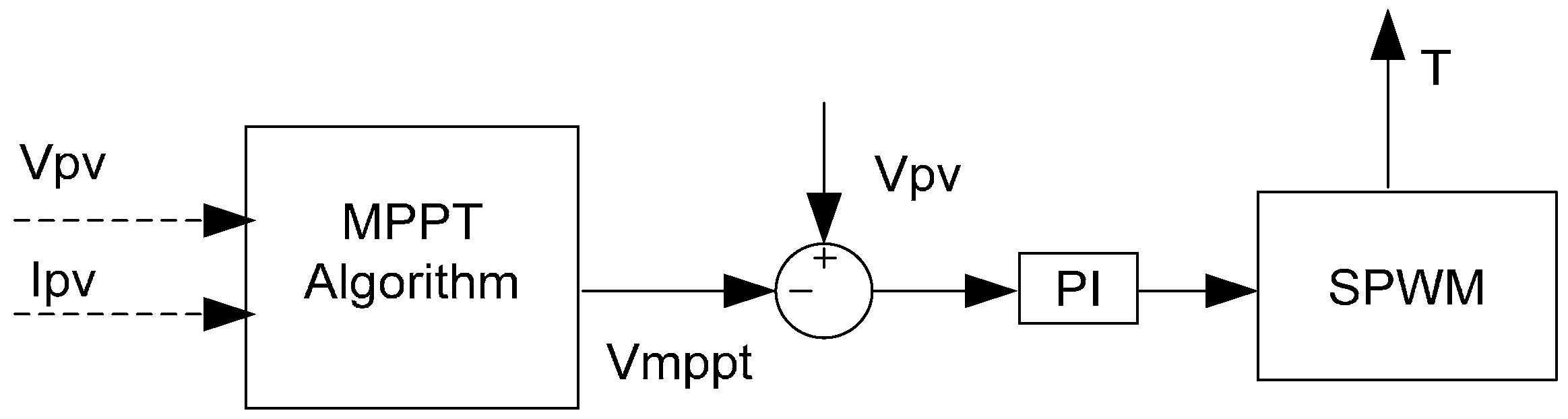
3.1. Maximum Power Point Tracking Algorithm

The PV module generated power feeding to the load is going through a regulated converter and a boost DC/DC converter is used between PV and load. This converter tracks the maximum power point of the PV system based on PWM signal generated by control unit [27]. Figure 7 presents the MPPT algorithm for PV arrays, which is developed on the incremental conductance algorithm. Additionally, Table 1 shows the control parameters. Through controlling duty cycle T of the boost DC/DC converter, PV modules keep operating at the maximum power point.

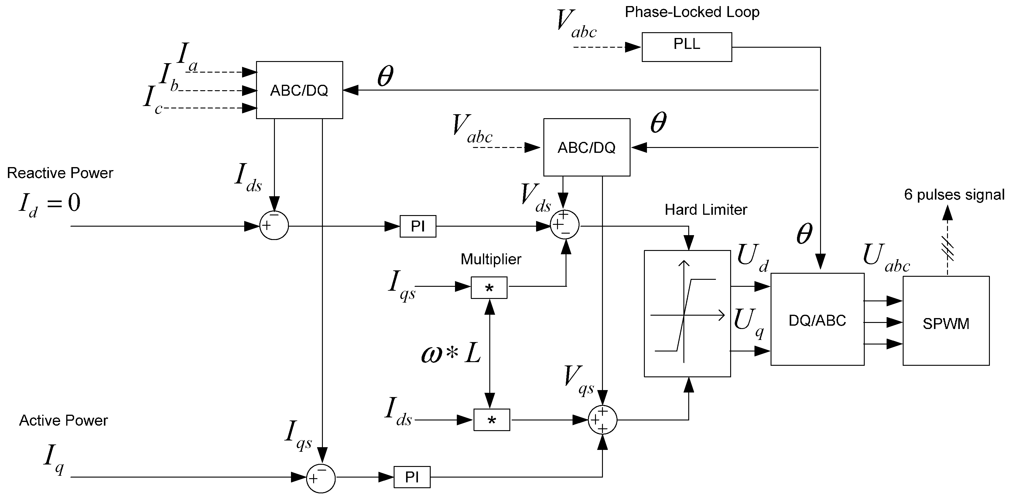
3.2. P-Q Decoupled Control Strategy

A P-Q decoupled control scheme using DQ transformation is utilized in this paper to realize a bidirectional power flow for the grid-connected converter, which is depicted in Figure 8.
The basic concept of the proposed method is the regulation of D-axis/Q-axis current corresponds to reactive/active power. Due to the only supply of active power being PV arrays, the reference current on D-axis (Id) is set to be zero herein. Moreover, an LC filter is applied to the grid-connected converter for better smoothing. Table 2 presents the control parameters for the grid-connected inverter.

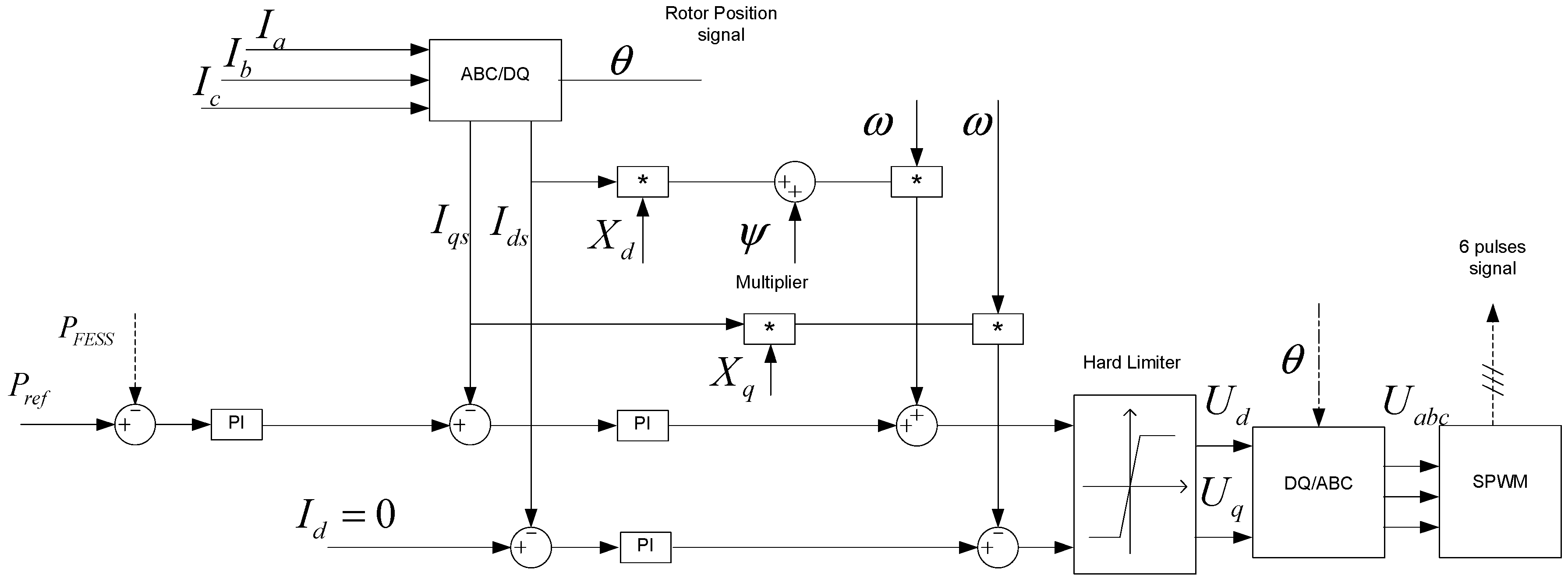
3.3. Constant Torque Angle Control Method

In order to achieve the goal of quickly responding to the power fluctuations caused by ship rolling, a double closed-loop control algorithm which made use of constant torque angle control integrated with SPWM is proposed to optimal manage the FESS operating mode, and is presented in Figure 9. Through controlling the charging/discharging power of FESS (Pref), the output power for the PV system can be smoothed to a specific value (250 kW).
From Figure 9, it can be seen that the torque angle is maintained at 90 degrees. As a result, the direct-axis current Id is made to be zero and the torque of PMSM is only determined by quadrature-axis current Iq. Thus, the torque for flywheel speeding up or slowing down can be controlled individually through adjusting PMSM quadrature-axis current Iq. The whole control block is made up of an inner current loop and outer active power loop for determining the amount of the output power from the FESS, and the control parameters for the FESS are shown in Table 3.

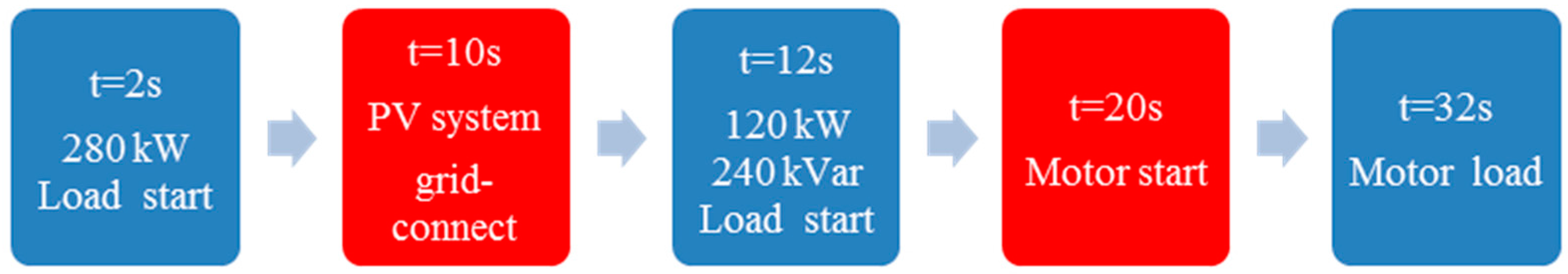
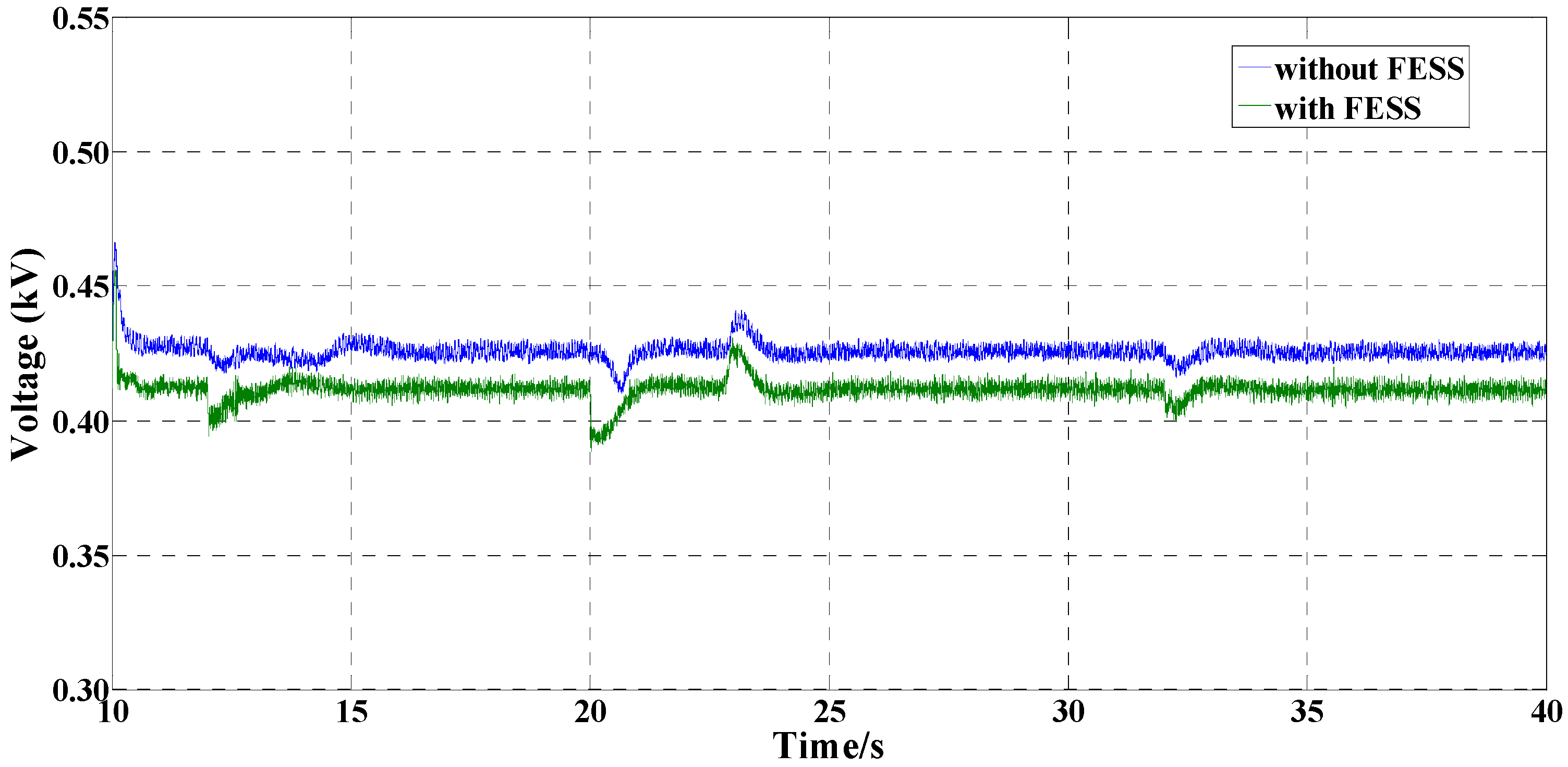
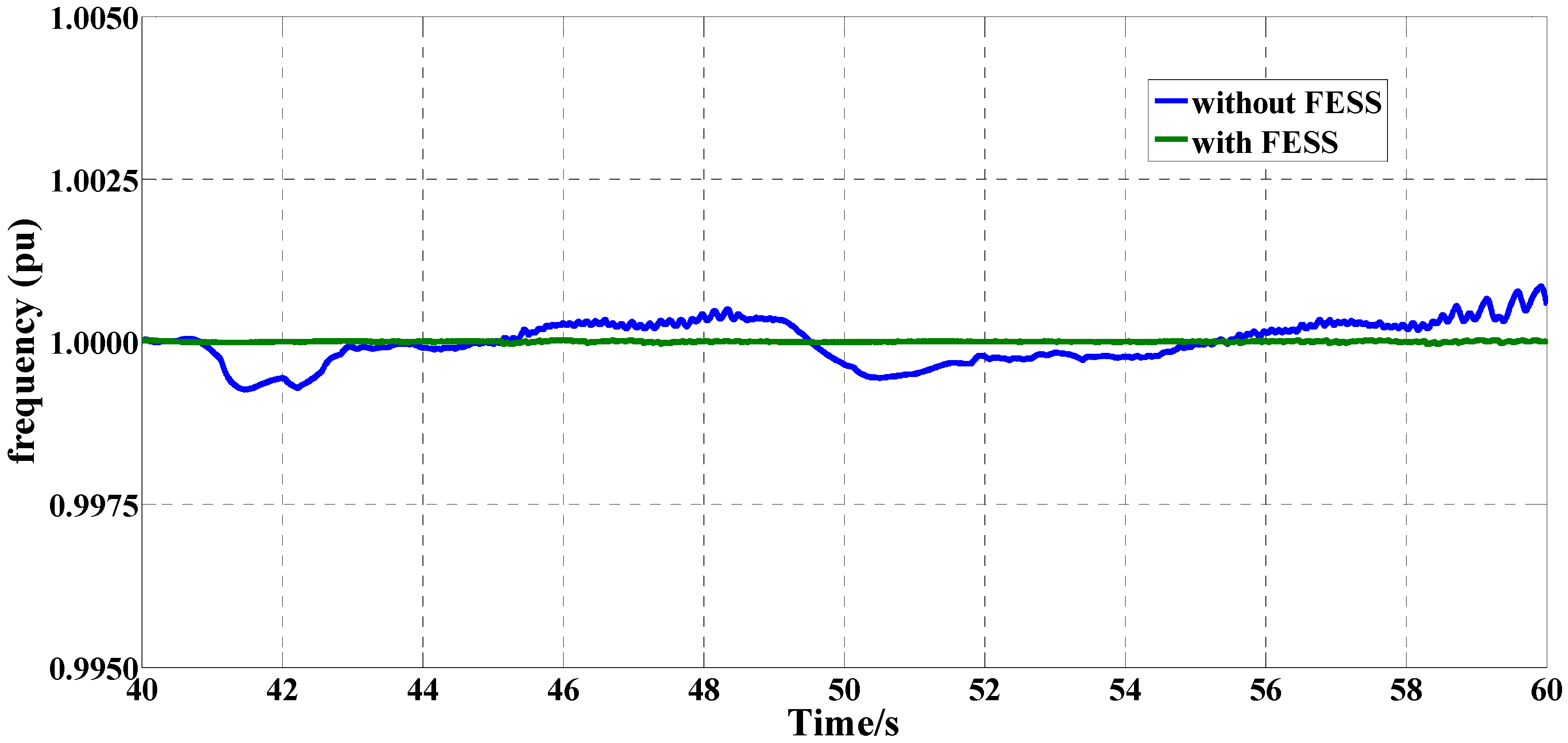
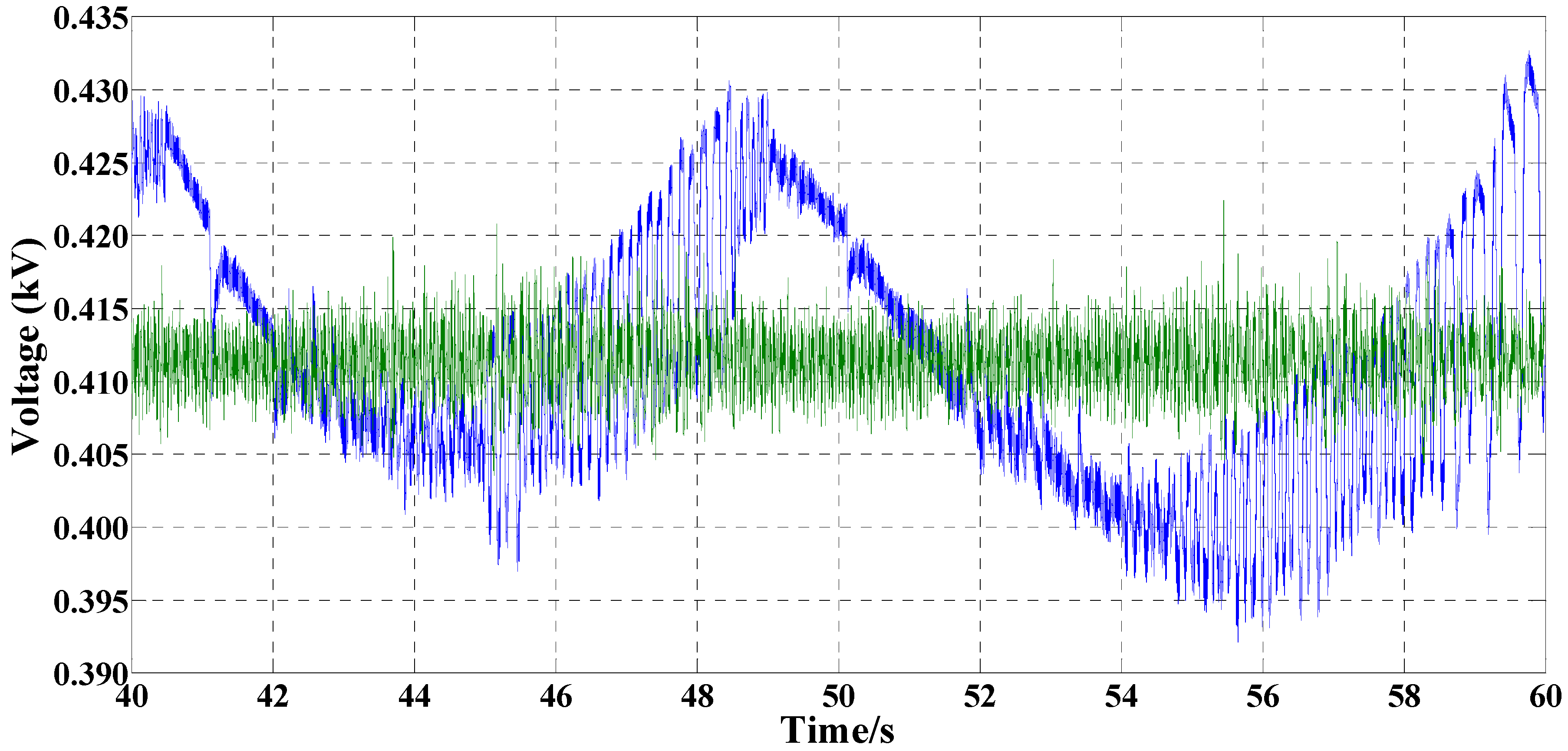
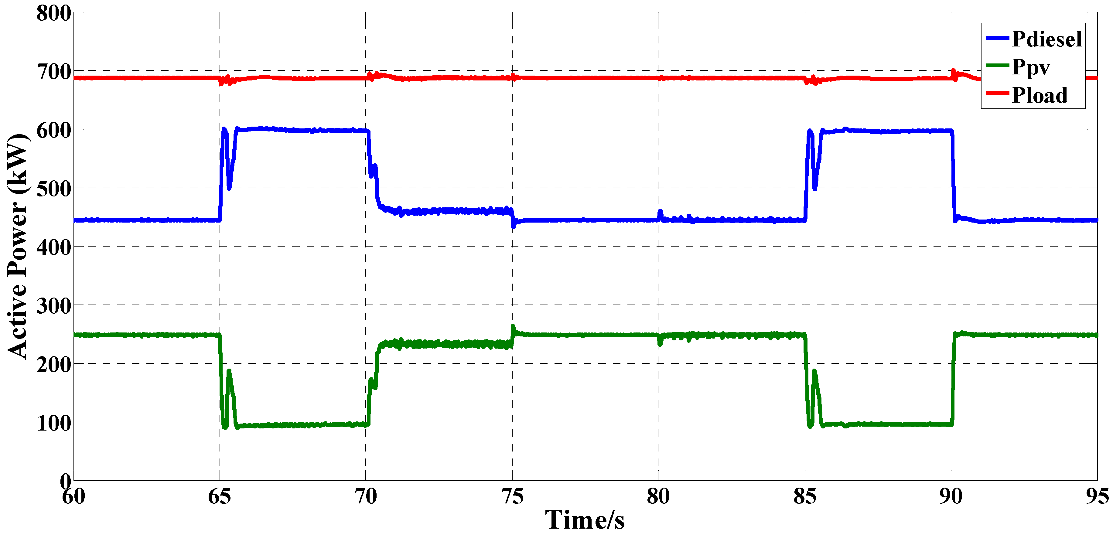
4. Simulation Analysis

The established hybrid PV/diesel/FESS ship power system shown in Figure 1 is selected to conduct the proposed control algorithm. The impacts of the integration of PV generation and FESS into the ship power system in three cases are studied and compared to demonstrate the effectiveness of the proposed control method. The voltage profiles and the output power of PV modules, diesel generator and FESS are shown as follows.
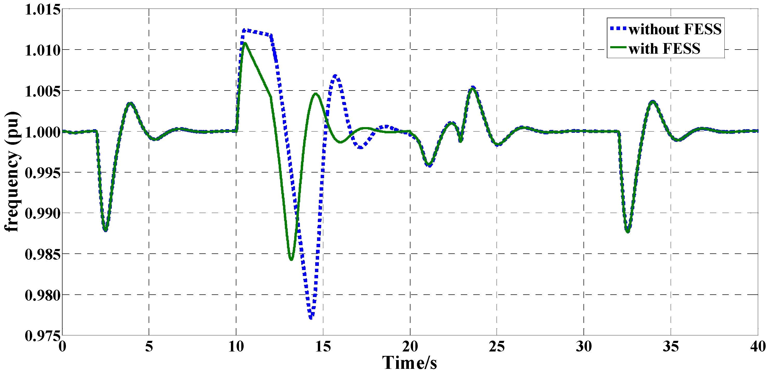
  • First Case: Stability analysis considering PV connection and ship load fluctuations;
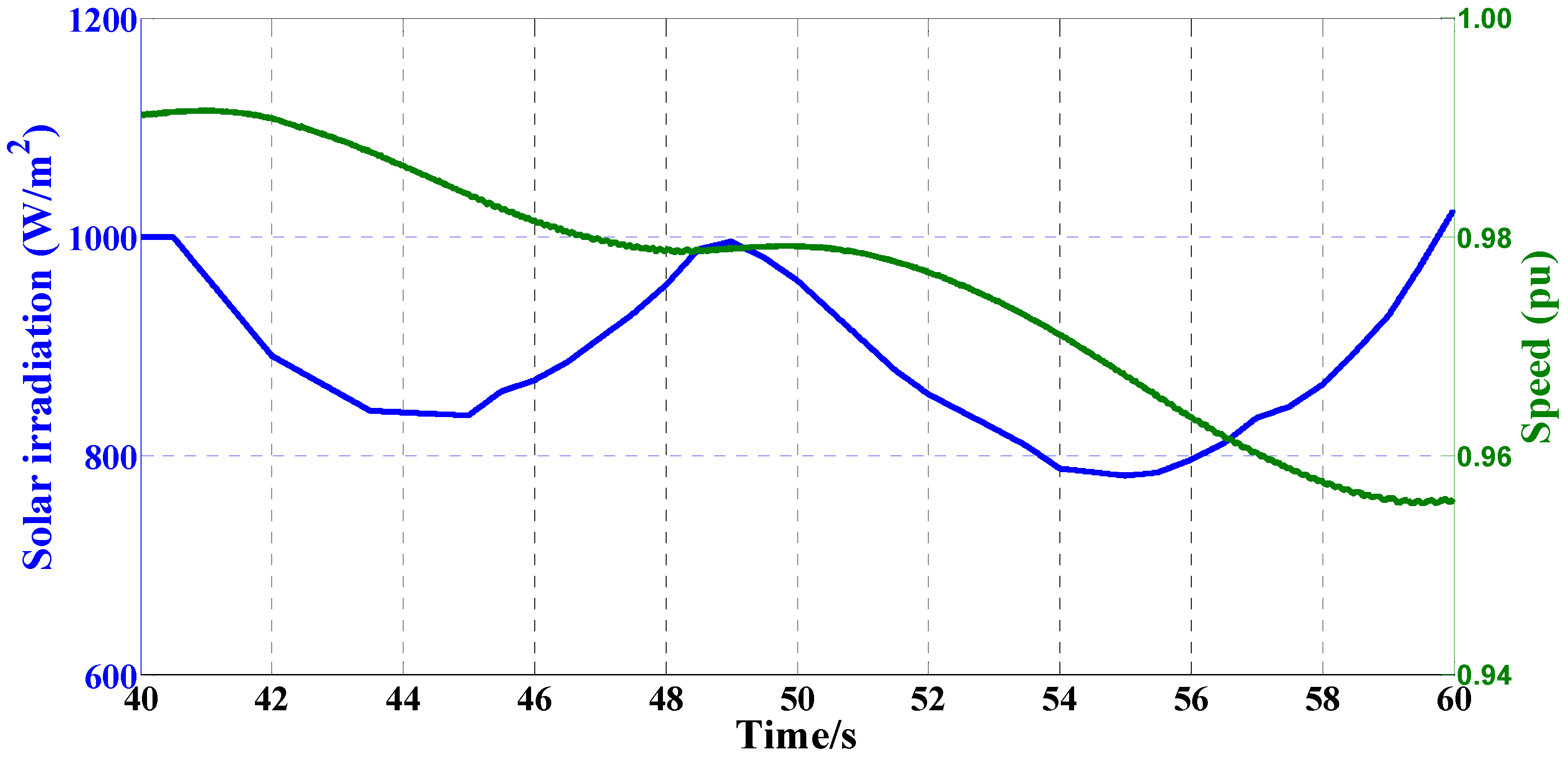
  • Second Case: Stability analysis considering ship rolling;
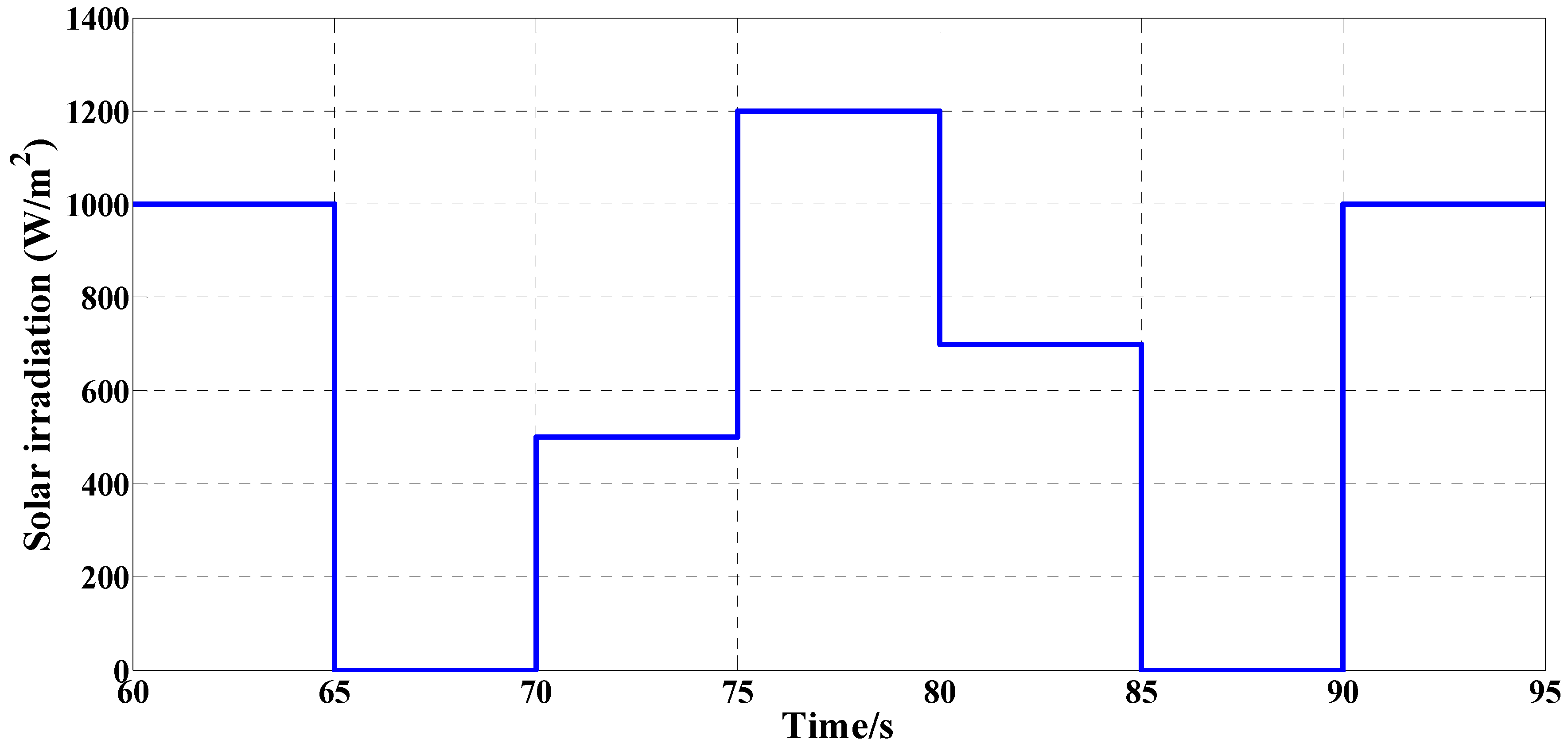
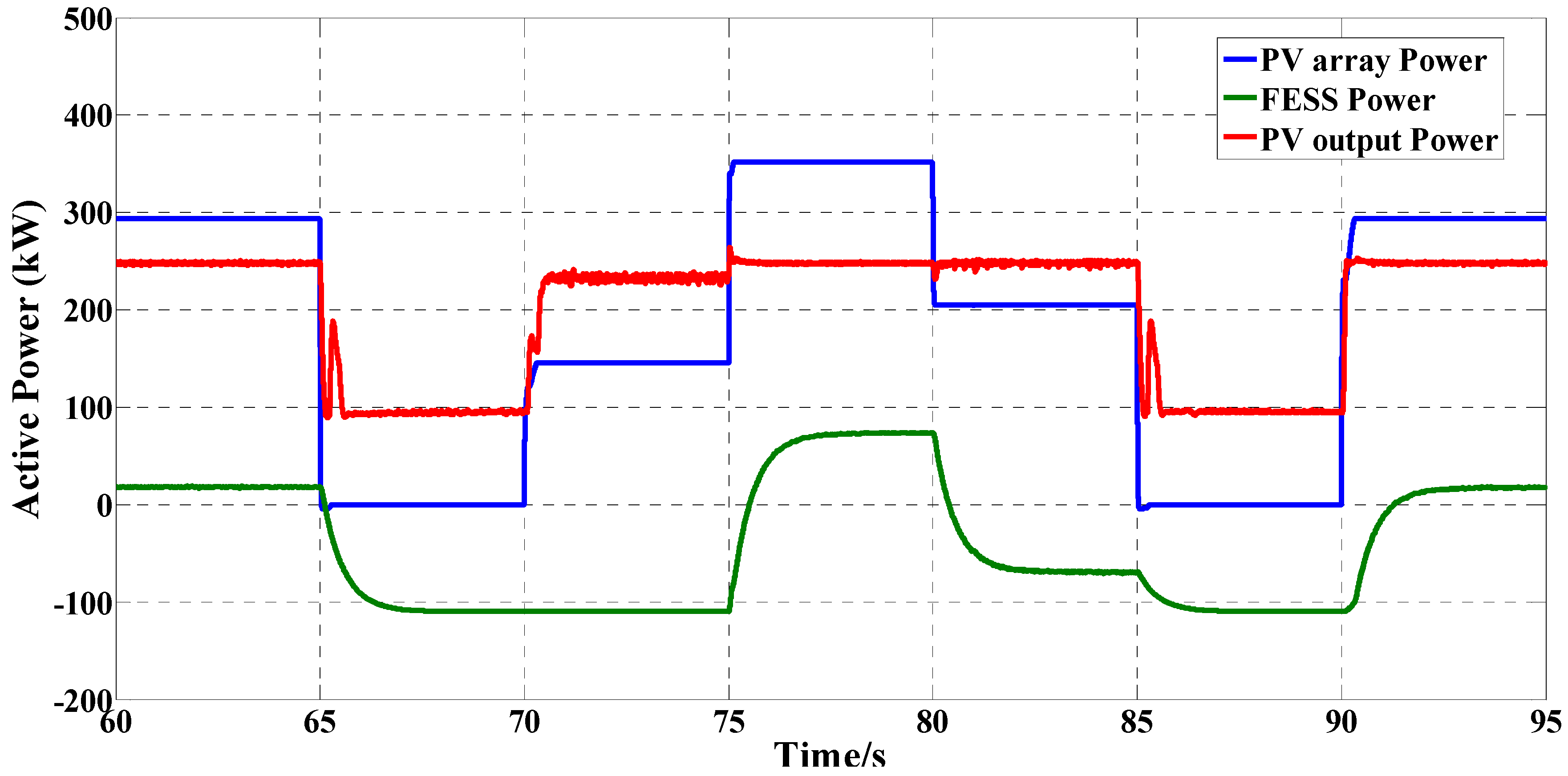
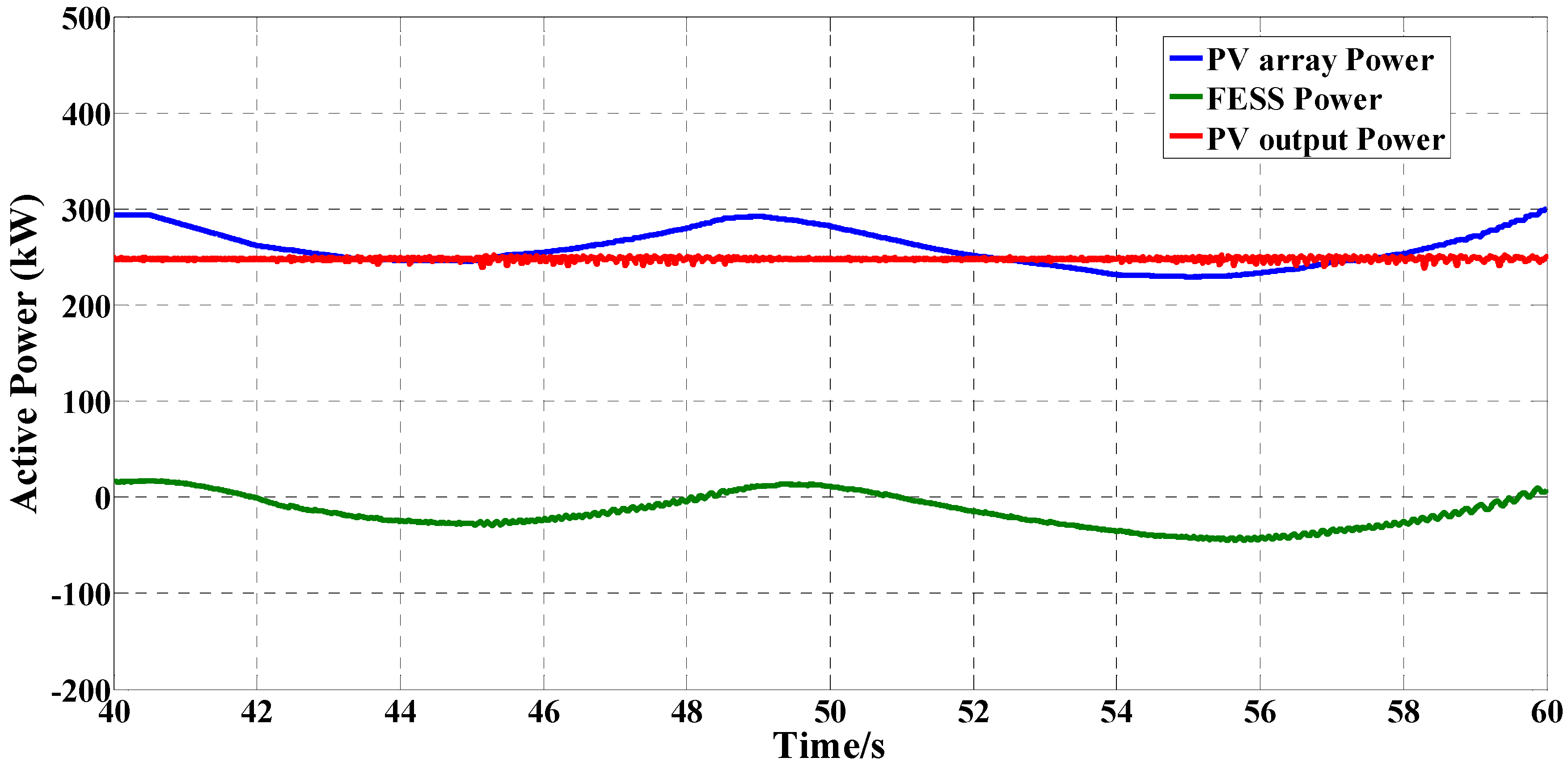
  • Third Case: Stability analysis considering the sudden changes of solar irradiation.
For the study, total simulation can be clearly divided into three stages. The first stage (First Case) starts from 0 s to 40 s and the main purpose of this stage is to simulate the transient progress caused by grid-connection and load fluctuations at a specific solar irradiation that is 1000 W/m2. The second stage (Second Case) is to study the impact of ship rolling on the PV generation system during 40 to 60 s. The last stage (Third Case) is to study hybrid system transient response when solar irradiation varies suddenly, which starts from 60 to 85 s.
First Case:
The ship power system begins with the load and PV generation system step by step, and the detailed operation progress is described in Figure 10. Specifically, a 280 kW resistive load is added to the system at t = 2 s; PV grid-connection happens at t = 10 s; one resistive load and reductive load with the size of 120 kW and 240 kVA respectively are added to the system; motor no-load starts at t = 20 s and a 350 HP load is added to the motor at t = 32 s.
The comparison between the system starting with FESS and without FESS is analyzed in Figure 11 and Figure 12. It can be seen that with the help of FESS, the voltage at PV side (DC bus) stays at the reference voltage which is 410 V and the ship system has a smaller frequency sag. In detail, the ship system with FESS has a maximum of frequency fluctuation of 0.016 pu that occurs when the PV generation system connects to the ship power grid, which is 7% lower than without FESS.
Second Case:
Introducing PV modules into the ship power system, it is necessary to consider the effect of ship rolling on the output power from PV generation system. According to the modified solar irradiation which is shown in Figure 2, the stability of the hybrid system is further discussed.
As shown in Figure 13, the output power from PV modules remains at 250 kW when the ship rolls by integrating FESS. Although the solar irradiation changes dramatically with the ship’s rolling, the excess power or insufficient power is totally compensated by FESS.
Similar to First Case, a comparison between the ship system with FESS and without FESS is explored to prove the significant role of FESS in smoothing the voltage and frequency fluctuations, which is shown in Figure 14 and Figure 15.
As seen above, the ship power system without FESS has to confront a risk of instability when the ship rolls heavily and the voltage at the DC bus even rises from 410 V to more than 430 V. Compared to this, the hybrid ship power system with FESS has a stable voltage stage. Furthermore, the SOC of FESS is presented in Figure 16 to show how the FESS operates to meet the change of the solar irradiation caused by the ship rolling.
Third Case:
According to the hourly solar irradiation provided by the SolarGIS company [28] along the navigation route from Dalian in China to Aden to Yemen, this paper analyzes the stability of the hybrid system, and one daily solar irradiation in the city of Singapore is used for the case study. Figure 17 depicts the solar irradiation in Singapore on 21 September 2014.
From the figure, it can be seen that the highest solar irradiation can reach almost 1350 W/m2. It is inevitable that the output power produced by the PV generation system will go through a sharp fluctuation, which will result in instability of the ship power system without FESS.
After choosing a typical value from Figure 17, a sudden change of the solar irradiation is shown in Figure 18 and the results of the system operation are presented as follows.
Figure 19 and Figure 20 present the power flow of different types of generation systems and load demand, respectively. More specifically, when the solar irradiation varies gradually, the power fluctuations can be regulated only by FESS. However, when the output power of the PV system experiences a large variation which is beyond the capacity of the FESS, the FESS operated with the diesel generator to keep the power balance.

5. Conclusions

In this paper, a hybrid PV/diesel/FESS ship power system is modeled and various advanced control strategies are developed for the hybrid system. Three different stability analyses of the ship system are discussed in detail. Unlike on land, the output power from the shipboard PV generation system varies with the movement of the ship so the impact of ship rolling is also considered. The simulation results demonstrate the effectiveness of the proposed control algorithm, and with the help of a flywheel energy storage system, the hybrid ship power system reduces the voltage and frequency fluctuations caused by the variations of system operating situations and the changes in solar irradiation.

Acknowledgments

This study was financially supported by the Ministry of Industry and Information Technology in cooperation with the Ministry of Finance under GK110900004, National Nature Science Foundation of China under 51109050, and fundamental research funds for the central universities under HEUCFX41401.

Author Contributions

All authors contributed to this collaborative work. Hai Lan and Yifei Bai performed the research and discussed the results; Shuli Wen, Ying-Yi Hong, David C. Yu, Jinfeng Dai and Peng Cheng suggested the research idea and contributed to the writing of the paper. All authors approved the manuscript.

Conflicts of Interest

The authors declare no conflict of interest.

Symbols and Abbreviations

The following symbols and abbreviations are used in this manuscript:
PV
Photovoltaic
ESS
energy storage system
FESS
Flywheel energy storage system
SPWM
Sinusoidal pulse width modulation
MARPOL
Marine Agreement Regarding Oil Pollution of Liability
PMSM
Permanent Magnet Synchronous Motor
SOC
State of charge
MPPT
Maximum power point tracking
DQ
Direct-axis and Quadrature-axis
PQ
Active power and reactive power
PWM
pulse width modulation
DC
direct current
Ipv, Vpv
PV array output current and voltage
T
Duty cycle
Vref
excitation voltage reference per-unit value
If, Ef
excitation current and voltage
W
diesel generator speed per-unit value
Wref
diesel generator speed reference
FL
the engine fuel intake
Tm
the engine output shaft torque per-unit value
J
the moment of inertia of flywheel rotor
ω
the angular speed of flywheel or system angular frequency
usd, usq
direct-axis and quadrature-axis voltage of stator winding
isd, isq
direct-axis and quadrature-axis current of stator winding
ψsd, ψsq
direct-axis and quadrature-axis flux linkage of stator winding
Ld, Lq
direct-axis and quadrature-axis inductance of stator winding
ωr
angular speed of rotor
Rs
resistance of stator
ψf
flux linkage of rotor
np
pairs of pole
Te
the electromagnetic torque of rotor
Ia, Ib, Ic
phase current
Vabc
phase to ground voltage
Vmppt
the maximum power point tracking voltage
θ
system voltage phase angle or rotor position of PMSM
L
inductance of grid-connected inverter
Xd, Xq
direct-axis and quadrature-axis reactance of PMSM
ψ
Magnetic strength of PMSM

References and Notes

  1. The International Convention for the Prevention of Pollution from Ships. Available online: http://www.imo.org/en/About/Conventions/ListOfConventions/Pages/International-Convention-for-the-Prevention-of-Pollution-from-Ships-%28MARPOL%29.aspx (accessed on 18 January 2016).
  2. Mitra, P.; Venayagamoorthy, G.K. An adaptive control strategy for DSTATCOM applications in an electric ship power system. IEEE Trans. Power Electron. 2010, 25, 95–104. [Google Scholar] [CrossRef]
  3. Hong, Y.; Pham, S.N.; Yoo, T.; Chae, K.; Baek, K.; Kim, Y.S. Efficient maximum power point tracking for a distributed PV system under rapidly changing environmental conditions. IEEE Trans. Power Electron. 2015, 30, 4209–4218. [Google Scholar] [CrossRef]
  4. Sundareswaran, K.; Sankar, P.; Nayak, P.S.R.; Simon, S.P.; Palani, S. Enhanced energy output from a PV system under partial shaded conditions through artificial bee colony. IEEE Trans. Sustain. Energy 2015, 6, 198–209. [Google Scholar] [CrossRef]
  5. Hajighorbani, S.; Radzi, M.A.M.; Kadir, M.Z.A.A.; Shafie, S. Dual search maximum power point (DSMPP) algorithm based on mathematical analysis under shaded conditions. Energies 2015, 8, 12116–12146. [Google Scholar] [CrossRef]
  6. Haroun, R.; El Aroudi, A.; Cid-Pastor, A.; Garcia, G.; Olalla, C.; Martinez-Salamero, L. Impedance matching in photovoltaic systems using cascaded boost converters and sliding-mode control. IEEE Trans. Power Electron. 2015, 30, 3185–3199. [Google Scholar] [CrossRef]
  7. Hill, C.A.; Such, M.C.; Chen, D.; Gonzalez, J.; Grady, W.M. Battery energy storage for enabling integration of distributed solar power generation. IEEE Trans. Smart Grid 2012, 3, 850–857. [Google Scholar] [CrossRef]
  8. Zhang, T.; Yue, D.; O’Grady, M.J.; O’Hare, G.M.P. Transient oscillations analysis and modified control strategy for seamless mode transfer in micro-grids: A wind-PV-ES hybrid system case study. Energies 2015, 8, 13758–13777. [Google Scholar] [CrossRef]
  9. Xu, Y.; Zhang, W.; Hug, G.; Kar, S.; Li, Z. Cooperative control of distributed energy storage systems in a micro grid. IEEE Trans. Smart Grid 2015, 6, 238–248. [Google Scholar] [CrossRef]
  10. Wu, D.; Tang, F.; Dragicevic, T.; Vasquez, J.C.; Guerrero, J.M. A control architecture to coordinate renewable energy sources and energy storage systems in islanded microgrids. IEEE Trans. Smart Grid 2015, 6, 1156–1166. [Google Scholar] [CrossRef]
  11. Akinyele, D.O.; Rayudu, R.K. Review of energy storage technologies for sustainable power networks. Sustain. Energy Technol. Assess. 2014, 8, 74–91. [Google Scholar] [CrossRef]
  12. Ramli, M.M.M.; Hiendro, A.; Twaha, S. Economic analysis of PV/diesel hybrid system with flywheel energy storage. Renew. Energy 2015, 78, 398–405. [Google Scholar] [CrossRef]
  13. Howlader, A.M.; Urasaki, N.; Yona, A.; Senjyu, T.; Saber, A.Y. A review of output power smoothing methods for wind energy conversion systems. Renew. Sustain. Energy Rev. 2013, 26, 135–146. [Google Scholar] [CrossRef]
  14. Sebastián, R.; Peña Alzola, R. Flywheel energy storage systems: Review and simulation for an isolated wind power system. Renew. Sustain. Energy Rev. 2012, 16, 6803–6813. [Google Scholar] [CrossRef]
  15. Boukettaya, G.; Krichen, L. A dynamic power management strategy of a grid connected hybrid generation system using wind, photovoltaic and Flywheel Energy Storage System in residential applications. Energy 2014, 71, 148–159. [Google Scholar] [CrossRef]
  16. Abdel-Khalik, A.S.; Elserougi, A.A.; Massoud, A.M.; Ahmed, S. Fault current contribution of medium voltage inverter and doubly-fed induction-machine-based flywheel energy storage system. IEEE Trans. Sustain. Energy 2012, 4, 58–67. [Google Scholar] [CrossRef]
  17. Hedlund, M.; Lundin, J.; de Santiago, J.; Abrahamsson, J.; Bernhoff, H. Flywheel energy storage for automotive applications. Energies 2015, 8, 10636–10663. [Google Scholar] [CrossRef]
  18. Ren, G.; Ma, G.; Cong, N. Review of electrical energy storage system for vehicular applications. Renew. Sustain. Energy Rev. 2015, 41, 225–236. [Google Scholar] [CrossRef]
  19. Lan, H.; Wen, S.; Hong, Y.-Y.; Yu, D.C.; Zhang, L. Optimal sizing of hybrid PV/diesel/battery in ship power system. Appl. Energy 2015, 158, 26–34. [Google Scholar] [CrossRef]
  20. Shih, N.C.; Weng, B.J.; Lee, J.Y.; Hsiao, Y.C. Development of a 20 kW generic hybrid fuel cell power system for small ships and underwater vehicles. Int. J. Hydrogen Energy 2014, 39, 13894–13901. [Google Scholar] [CrossRef]
  21. Lee, K.J.; Shin, D.S.; Lee, J.P.; Yoo, D.W.; Choi, H.K.; Kim, H.J. Hybrid photovoltaic/diesel green ship operating in standalone and grid-connected mode in South Korea—Experimental investigation. In Proceedings of 2012 IEEE Vehicle Power and Propulsion Conference (VPPC), Seoul Olympic Parktel, Seoul, Korea, 9–12 October 2012.
  22. Study on the Application of Photovoltaic Technology in the Oil Tanker Ship, Grant No. GK110900004, Execution period: January 2013–December 2015.
  23. Yan, R.; Saha, T.K.; Modi, N.; Masood, N.-A.; Mosadeghy, M. The combined effects of high penetration of wind and PV on power system frequency response. Appl. Energy 2015, 145, 320–330. [Google Scholar] [CrossRef]
  24. Tankari, M.A.; Camara, M.B.; Dakyo, B.; and Lefebvre, G. Use of ultracapacitors and batteries for efficient energy management in wind-diesel hybrid system. IEEE Trans. Sustain. Energy 2013, 4, 414–424. [Google Scholar] [CrossRef]
  25. Mukoyama, S.; Matsuoka, T.; Hatakeyama, H.; Kasahara, H.; Furukawa, M.; Nagashima, K.; Ogata, M.; Yamashita, T.; Hasegawa, H.; Yoshizawa, K.; et al. Test of REBCO HTS magnet of magnetic bearing for flywheel storage system in solar power system. IEEE Trans. Appl. Supercond. 2015, 25, 7–10. [Google Scholar] [CrossRef]
  26. Valencia, P.A.O.; Ramos-Paja, C.A. Sliding-mode controller for maximum power point tracking in grid-connected photovoltaic systems. Energies 2015, 8, 12363–12387. [Google Scholar] [CrossRef]
  27. Singaravel, M.M.R.; Daniel, S.A. MPPT with Single DC–DC converter and inverter for grid-connected hybrid wind-driven PMSG–PV system. IEEE Trans. Ind. Electron. 2015, 62, 4849–4857. [Google Scholar] [CrossRef]
  28. Solar and PV data. Available online: http://solargis.info/doc/solar-and-pv-data (accessed on 28 May 2015).
Figure 1. Hybrid ship power system configuration.
Inventions 01 00005 g001
Figure 2. Modified solar irradiation considering ship rolling.
Inventions 01 00005 g002
Figure 3. PV generation system.
Inventions 01 00005 g003
Figure 4. Diesel generation system.
Inventions 01 00005 g004
Figure 5. Flywheel energy storage system.
Inventions 01 00005 g005
Figure 6. Bidirectional inverter.
Inventions 01 00005 g006
Figure 7. Control strategy for PV system.
Inventions 01 00005 g007
Figure 8. General control block diagram for the grid-connected inverter.
Inventions 01 00005 g008
Figure 9. General control block diagram for flywheel energy storage system.
Inventions 01 00005 g009
Figure 10. Operation processes in the first case.
Inventions 01 00005 g010
Figure 11. System frequency.
Inventions 01 00005 g011
Figure 12. DC voltage.
Inventions 01 00005 g012
Figure 13. Active power output of PV array, FESS and PV system.
Inventions 01 00005 g013
Figure 14. System frequency.
Inventions 01 00005 g014
Figure 15. DC voltage.
Inventions 01 00005 g015
Figure 16. Flywheel speed varies with the solar irradiation.
Inventions 01 00005 g016
Figure 17. Solar irradiation at specific day in Singapore.
Inventions 01 00005 g017
Figure 18. Typical selected solar irradiation for PV system.
Inventions 01 00005 g018
Figure 19. Active power output of PV array, FESS and PV system.
Inventions 01 00005 g019
Figure 20. Output power of PV and diesel and load demand.
Inventions 01 00005 g020
Table 1. Control parameters for PV system.
MPPT ControlPISPWM
Open-circuit voltageShort-circuit currentSampling intervalPIFrequency
450 V847 A0.001 s30.0110 kHz
Table 2. Control parameters for grid-connected inverter.
LC FilterCurrent ControlVoltage ControlSPWM
InductanceCapacitancePIPIFrequency
0.5 mH500 uF500.0011200.00112 kHz
Table 3. Control parameters for FESS.
PMSMCurrent ControlActive Power Control
Rated VoltageRated FrequencyMoment of Inertia JPIPI
200 V250 Hz58.824 kg*m215000.00011000.001

