1. Introduction
Selective Compliance Articulated Robot Arm (SCARA) robots have experienced exponential adoption in industrial applications due to their high-speed performance and compact design. In 1978, Hiroshi Makino et al. laid the foundation for the creation of SCARA robots, which have become central players in various industries [
1,
2]. SCARA robots are widely used in applications that require fast movement execution, such as pick-and-place tasks in the PCB manufacturing industry and sorting items from fast-moving conveyor lines [
3,
4]. In these applications, speed and accuracy are critical, and the ability to dynamically adapt to the environment is essential for effective task execution. Although advanced perception systems have been frequently utilized in robots, their implementation in SCARA robots is relatively rare [
5,
6]. The integration of visual perception systems in SCARA robots offers significant advantages, including the ability to address challenges such as accumulative coordinate errors and the need for adaptability in dynamic environments. These advancements enhance the performance and reliability of SCARA robots in precision-driven tasks.
In the SCARA robot work environment, two types of categories can be classified as sequential and autonomous [
7,
8]. In a sequential system, precision is crucial as the robot is programmed to handle objects with exacting accuracy. In contrast, an autonomous robot determines object position, orientation, and approach direction independently, adapting to errors in object location. In the case of SCARA robots, they are used for tasks demanding precision and repetition, such as pick-and-place, where maintaining maximum speed between coordinates is essential. Therefore, most SCARA robots are classified as autonomous [
9]. In autonomous robot control systems, visual feedback is essential and is achieved through the use of a camera and machine vision [
10]. However, traditional methods like binocular stereo and active monocular stereo have not satisfactorily performed well in real-time coordinate estimation due to their time-intensive nature [
11]. Hence, the most typical novel approach is image-based visual servoing, where image features act as controlled variables, and desired robot movement is estimated using Jacobian metrics (image Jacobian) [
12].
Based on the camera-mounted position of the robot, two types of visual servoing methods can be identified. Position-Based Visual Servoing (PBVS) [
13] method involves using a fixed-position camera and moving the end-effector, which can be more complicated due to the need for complex machine vision algorithms to interpret the camera’s fixed perspective. In contrast, the image-based visual servoing (IBVS) [
14] method employs a camera mounted on the end-effector itself, which simplifies the setup and interpretation of visual feedback. The accuracy of the robot control system is directly proportional to how effectively the robot reaches its desired coordinates in a 3D workspace in the minimum time.
Due to the high-speed operation of SCARA robots, position errors can accumulate, requiring effective control strategies to minimize vibrations and improve accuracy. Several studies have explored vision-based approaches and depth estimation techniques to enhance SCARA robot performance in precision tasks [
15,
16,
17]. Machine vision systems have been integrated with SCARA robots for tasks such as picking and placing PCB components, achieving high accuracy through hardware and algorithmic improvements. Additionally, research on real-time depth estimation has investigated various techniques, including structured light projection, Time-of-Flight (ToF) measurement, and laser triangulation, each offering advantages and limitations based on object size and system complexity.
Table 1 presents a comparative analysis on robotic depth estimation and pose optimization for SCARA robots, highlighting advancements relevant to PCB repair applications.
Several studies have explored real-time depth estimation techniques, including structured light projection [
24], Time-of-Flight (ToF) measurement [
25], Laser Imaging Detection and Ranging (LIDAR) [
26], binocular stereo vision, and active monocular stereo. While these methods have demonstrated good accuracy, they often pose challenges in real-time applications due to complexity and processing constraints. For instance, Adaptive Structured Light (ASL) encoding achieves high accuracy in depth estimation but requires intensive computation, making it less feasible for real-time industrial applications [
23]. Conversely, laser triangulation techniques have been widely used for non-contact depth measurement [
22]. While effective for larger objects, their precision may be compromised when applied to small-scale components, such as SMD Integrated Circuits (ICs) on PCBs, due to the reduced accuracy at finer resolutions [
27]. Traditional binocular stereo vision systems rely on disparity calculations between two camera views to estimate depth. However, these systems require extensive computational resources for real-time processing and are prone to inaccuracies when dealing with miniature components like SMDs due to low disparity variations. Active monocular stereo techniques improve depth perception by incorporating controlled illumination, but they introduce additional hardware complexities and are less effective in high-speed operations. Structured light projection methods employ encoded light patterns to reconstruct depth maps with high precision. Although effective, they demand specialized hardware and considerable processing time, making them less suitable for dynamic environments like PCB repair. Time-of-Flight (ToF) sensors estimate depth by measuring the time it takes for light pulses to reflect off surfaces. While ToF sensors can achieve high accuracy, their performance is heavily influenced by surface reflectivity and ambient lighting conditions, leading to inconsistencies in depth estimation for metallic PCB components. Similarly, LIDAR systems use laser pulses to construct detailed depth maps, but their application in PCB repair is limited by their high cost, sensitivity to small-scale features, and the need for continuous scanning.
SCARA robots, initially designed for high-speed planar movements along the X and Y axes, have seen increasing adoption in tasks that require greater precision, such as SMD component placement, PCB assembly, and repair. However, a major challenge in these applications is the precise estimation of the Z-axis position, which is crucial for ensuring proper depth control during soldering, desoldering, and other fine manipulation tasks. Addressing this limitation is critical for improving automation reliability in PCB manufacturing and repair processes.
To overcome these challenges, this study develops a SCARA robot control system capable of accurately estimating real-world coordinates, with a particular emphasis on depth measurement for PCB repair applications. The proposed system integrates an IBVS for X and Y coordinate estimation and a simplified laser triangulation method for Z-axis depth measurement. IBVS is computationally efficient for real-time applications, as it eliminates the need for complex 3D reconstructions required by methods like binocular stereo and structured light projection. A camera mounted on the SCARA robot’s end-effector tracks object features and translates them into movement commands using Jacobian-based control, ensuring accurate coordinate estimation without external calibration. For depth estimation, laser triangulation is preferred over ToF and LIDAR due to its superior precision in close-range measurements. By projecting two laser beams at fixed angles onto the PCB surface and analyzing their displacement with a camera, the method uses linear regression to establish a direct depth correlation. Laser triangulation offers sub-millimeter accuracy, making it ideal for PCB repair tasks where even slight depth errors can cause misalignment. Additionally, it is resilient to surface reflectivity variations and consistent across different PCB materials. The combination of IBVS and laser triangulation optimizes real-time performance, precision, and computational efficiency, offering high accuracy without the complexity or hardware dependence of alternative depth estimation methods.
2. Materials and Methods
2.1. System Configuration of the Selective Compliance Articulated Robot Arm Robot
The SCARA robot utilizes a Revolute-Prismatic-Revolute (RPR) linkage system for precise 3D movement, featuring two 24-75VDC/10A ClearPath SD brushless servo motors (TEKNIC INC., New York, NY, USA) at the revolute joints, connected via a 3 mm pitch High Torque Drive (HTD) belt with a 5:1 gear ratio for accurate X and Y-axis motion. The prismatic joint, equipped with the same servo motor, is connected to a lead screw, enabling vertical movement along the Z-axis. The end-effector integrates a Logitech C270 USB camera (720p, 30 fps, 55° DFOV) (Logitech Engineering & Designs India Private Limited, Chennai, India) and two 5 V/40 mA 70045 adjustable laser diodes (650 nm wavelength) positioned at a 70° angle to enhance visual and depth perception. Control is provided by a ClearCore Industrial I/O and Motion Controller (TEKNIC INC., USA) powered by a 32-bit ARM Cortex M4F processor. The system is powered by a 75 VDC Amazon Intelligent Power Center 5 for the servo motors and a 24 VDC/10 A MeanWell DR-120-24 power supply for the controller, ensuring efficient and reliable operation.
Figure 1a depicts the parameterized Computer-Aided Design (CAD) of the model representing the implemented 3 Degrees of Freedom (DOF) SCARA robot. This CAD model was designed using SolidWorks 3D CAD 2021 (Dassault Systèmes SolidWorks Corporation, Waltham, MA, USA) [
28].
Figure 1b illustrates the developed physical model, which was applied for the industrial application. Its overall system performance was measured by conducting several trials on axis accuracy and execution time. Those trials will give a comprehensive idea about the accuracy of the robot and the possibility of using this novel approach in the industrial sector.
2.2. Kinematics
2.2.1. Forward Kinematics
In preparation for designing the motion control of the robot, it is crucial to establish both forward and inverse kinematics equations. Forward kinematics equations enable the determination of the end-effector’s pose (position and orientation) based on the robot’s joint variables. Conversely, inverse kinematics equations allow for the computation of the joint variables required to achieve a desired end-effector pose. The forward kinematic equation, developed using the Denavit–Hartenberg (DH) method, employs a “4 × 4” matrix, referred to as a homogeneous transformation matrix. This matrix encapsulates both position and orientation and is represented by Equation (1). The definitions of kinematic parameters in a homogeneous transformation matrix are represented in
Table 2.
The derivation of the forward kinematic equation in this study serves a critical role in both theoretical understanding and practical application. Predicting the end-effector pose of the SCARA robot based on joint angles underpins essential tasks, such as motion planning and control. The Denavit–Hartenberg (DH) table for deriving the forward kinematic equation is illustrated in
Table 3.
Once the DH table entries are finalized based on the assigned frames, the next step involves deriving homogeneous transformation matrices between each pair of joints. These matrices are obtained by multiplying individual transformation matrices successively. The result is an overall transformation matrix that encompasses both the orientation and position parameters of the end-effector in the robot’s base frame. This comprehensive representation offers insight into the manipulator’s spatial configuration.
The attributes of the end-effector, obtained through the transformation matrix and expressed via Equations (2)–(4), play a pivotal role in guiding the motion control strategy outlined in this study. By providing precise information about the end-effector’s position and orientation, these attributes facilitate accurate trajectory planning and manipulation tasks, enhancing the overall efficiency and effectiveness of the proposed motion control method.
2.2.2. Inverse Kinematics
Inverse kinematics was used to determine the values of joint variables based on the end-effector’s given position and orientation data. The solution to inverse kinematics typically yields one or more solutions, necessitating the appropriate solution. Therefore, MATLAB R2021a (MathWorks Inc., Natick, MA, USA) simulation tools are used to simulate the robot in a virtual environment, aiding in identifying and validating suitable solutions. Utilizing Equations (2)–(4), a new equation can be derived to ascertain the joint angles by providing the link lengths and the coordinates of the point to which the robot’s end-effector needs to be positioned. The following Equation (5) demonstrates the method for determining the joint angles from the previously derived forward kinematics equations. Upon rearranging the equations mentioned above and solving for “
θ1,
θ2”, the following expressions are obtained:
The “fsolve” function is a numerical solver in MATLAB designed explicitly for finding roots of systems of non-linear equations. In the context of inverse kinematics, “fsolve” was utilized to solve the coupled Equation (5) simultaneously, providing values for the joint angles ( and ) that satisfy the specified conditions.
2.3. Motion Controlling Methods
2.3.1. Visual Servoing-Based Real World Coordinate Estimation from Pixel Coordinates
To address the challenge of estimating a precise location and guiding the end-effector, a visual servoing technique is employed, leveraging visual feedback and information for motion control of the robotic system. To implement object tracking for the SCARA robot, the Channel and Spatial Reliability Tracking (CSRT) tracker is used from OpenCV, which is a computer vision library initially developed by Intel. Renowned for its high accuracy in real-time object tracking within a video feed, the CSRT tracker is employed due to compatibility issues between MATLAB and the tracker. Consequently, the object tracking algorithm operates in the Python 3.8.3 environment, using a Region of Interest (ROI) defined by the user to facilitate real-time tracking.
While the CSRT tracker is in active mode, tracked coordinates are communicated to the central control platform via serial communication. The main control platform processes these coordinates, determining the required direction for the movement of the robot. Subsequently, values are transmitted to the microcontroller to control the motions of the robot. This effective iterative process continues until the robot precisely aligns with the center of the track, pinpointing the location of the object in the X and Y planes. This approach eliminates complex calculation methods to convert pixel coordinates to real-world coordinates and mitigates accumulative errors during repetitive tasks with the SCARA robot.
2.3.2. Integration of Laser Triangulation for Depth Perception Using a Single Camera
To enhance the depth perception of the developed system, a laser triangulation technique was used to measure the distance to a target by observing the reflections of laser beams with a camera. Two laser lights were mounted at an approximate angle of 70 degrees to project onto the surface (base) of the robot. The variation in the distance between these laser points corresponded to changes in depth. As the depth increased, the distance between the two laser points decreased, and conversely, as the depth decreased, the distance between the two laser points increased. This fundamental principle formed the basis for measuring depth using a single camera through laser triangulation. Accurate depth perception was achieved by measuring laser reflections and filtering the background using color filtering techniques and image masking in OpenCV [
29]. Initial measurements revealed discrepancies between the laser point distances and actual depth values obtained using a Vernier caliper. Linear regression was applied to address this issue and enhance measurement accuracy.
Among commonly used depth estimation techniques, laser triangulation was selected for its precision and suitability for close-range applications. Rangefinders, based on the time-of-flight (TOF) principle, measure the time taken by a laser or infrared (IR) beam to travel to an object and return. While effective for long distances, rangefinders lack precision in close-range tasks and are prone to errors caused by environmental noise and reflective surfaces, making them less ideal for small-scale tasks such as PCB repair. Laser triangulation, by projecting two laser beams onto a target surface and analyzing their displacement via a camera, achieves sub-millimeter accuracy. Its geometric approach is robust against reflective surfaces, and color filtering enhances measurement reliability. Although it requires careful calibration, laser triangulation provides real-time measurements, making it suitable for dynamic systems like SCARA robots. Other techniques, such as structured light and stereo vision, were considered but were found to be less suitable for real-time applications due to their computational demands. Structured light generates depth maps by projecting patterns onto surfaces, while stereo vision uses two cameras to calculate depth from image disparities. These methods require significant processing power and precise calibration, limiting their applicability for high-speed operations. The integration of laser triangulation into the SCARA robot system ensures consistent and accurate depth estimation, particularly in close-range applications like PCB repair. This method effectively enhances the robot’s capabilities for tasks demanding both precision and speed.
Figure 2 illustrates the system architecture and process flow of the designed SCARA robot, incorporating object tracking, simulation, motion control, and kinematic calculations.
The machine vision system also incorporates an advanced calibration mechanism that dynamically adjusts its parameters based on the PCB’s color and reflection levels. Since the output of the laser triangulation algorithm can vary significantly depending on these factors, sometimes even failing to detect laser spots accurately, the system first analyzes the PCB’s surface properties. By identifying its color and brightness levels, the algorithm fine-tunes its calibration values accordingly, ensuring improved laser point detection and enhancing overall measurement accuracy.
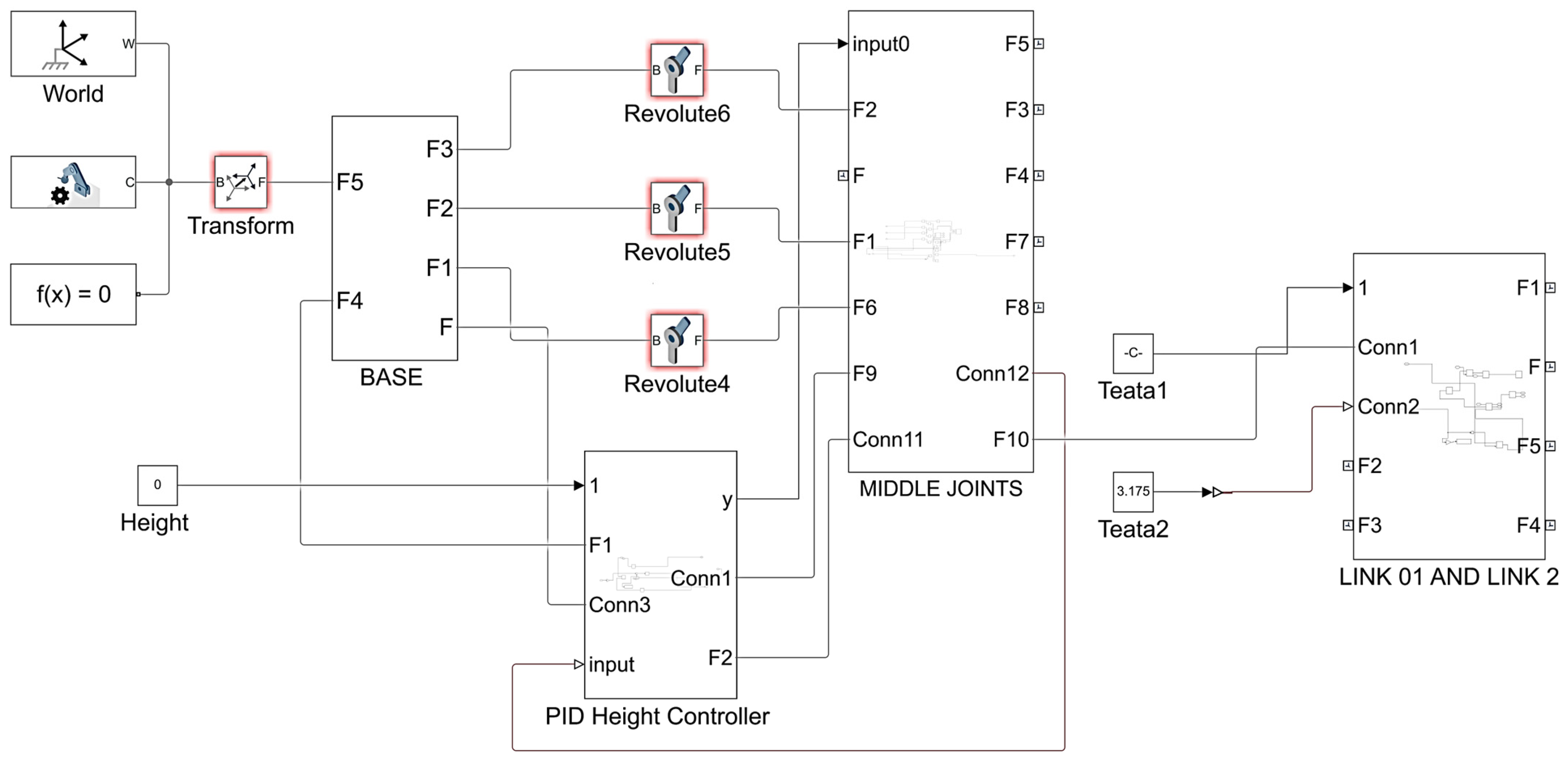
2.4. Simulation of the Robot Design
Before constructing the physical robot, component functionality and performance were validated through simulation. To create a dynamic model of the robot, the SolidWorks model was exported to MATLAB and converted into a Simulink model using the Simscape Multibody Link library. This library enables the incorporation of rigid body dynamics and kinematic constraints within the simulation environment. During the modeling process, careful attention was paid to identifying and rectifying configuration errors within the imported SolidWorks model. This ensured an accurate representation of the physical robot’s mechanical structure and prevented discrepancies in simulation results. To evaluate the movement of the SCARA robot’s X, Y, and Z axes, proportional-integral-derivative (PID) controllers were implemented within the Simulink model for the joints. This feedback control system facilitated smooth and precise vertical movement, closely resembling the anticipated behavior of the physical robot. Moreover, joint input signals were applied through a custom MATLAB script to replicate desired motion commands and identify any potential deviations between simulated and expected dynamics. The simulation platform, designed to validate and optimize the single camera-based coordinate tracking and depth perception method for motion control in SCARA robots, as depicted in
Figure 3, yielded valuable insights into the robot’s kinematic limitations. Specifically, the singularity point of the SCARA robot was identified, and suitable angular offsets for each joint were determined. These critical findings were subsequently integrated into the physical model’s design, enhancing its accuracy and reliability.
2.5. Interfacing and Controlling Servo Motors with MATLAB
Seamless control and integration of the ClearPath SD servo motors with MATLAB were accomplished through the ClearCore Motion Controller, as depicted in
Figure 2. To optimize control precision, the controller was programmed in C++. This ensured the accurate and efficient interpretation of rotational angle commands received from MATLAB via serial communication. Conversely, improvements were made to enhance system stability by incorporating acceleration and deceleration functions. These functions, implemented using the AccelStepper library (an open-source tool developed by Mike McCauley), were crucial in stabilizing motor operations. This not only improved system stability but also minimized camera system flexure, reducing its impact on image quality and enhancing positioning accuracy.
2.6. Communication Interfacing Between Hardware and Software
In the proposed method, a single camera served as a direct interface with the computer, enabling the transfer of video and image frames through the Universal Serial Bus (USB) protocol. The image processing algorithm, developed in the Python environment and incorporating the CSRT Tracker for object tracking, was configured to receive and process data from the camera, specifically video and image frames. To facilitate communication between the image processing algorithm and MATLAB’s control system, a virtual serial communication channel was established, operating at a baud rate of 9600 bits per second. This required configuring a virtual serial port driver, which enabled the computer to generate virtual communication ports within its operating environment. Subsequently, the MATLAB control algorithms were designed to execute inverse kinematics calculations, incorporating robust process control methodologies. The instructions derived from these calculations were communicated to the motion controller through the established serial communication link. This coordinated system allowed MATLAB to orchestrate the movement of the SCARA robot with high precision, ensuring effective performance during operation.
2.7. Experimental Setup and Testing Conditions
To ensure reliable evaluation of the proposed system, a well-structured experimental setup was established, focusing on selecting appropriate testing depths, controlling environmental conditions, and implementing repeatability measures. The testing depths were selected based on common working distances in PCB repair environments, ensuring comprehensive evaluation of system accuracy across different depths. Three fixed depths, 230 mm, 280 mm, and 350 mm, were chosen to analyze performance variations in real-world coordinate estimation. These depths allow assessment of the method robustness at varying distances and its ability to maintain precision in practical applications.
The experimental setup included a camera and laser lights that were fixed to the end-effector of the SCARA robot. This configuration ensured that the relative positioning of the vision and depth measurement system remained consistent throughout the trials. Ambient lighting was controlled using an enclosed workspace with diffused LED illumination to minimize shadowing and reflections. The PCB samples were placed on an anti-reflective surface to prevent inaccuracies due to unwanted reflections from the metallic surface of the board. To mitigate external disturbances, color filtering and background noise reduction techniques were implemented in the image processing algorithm. Image masking was applied to enhance laser point visibility, ensuring consistent depth estimation.
Each experiment was conducted over multiple trials to ensure repeatability and statistical reliability. For real-world coordinate estimation using the visual servoing method, multiple trials were conducted at the three specific depths (230 mm, 280 mm, and 350 mm) to evaluate accuracy along the X and Y axes. For the laser triangulation-based depth estimation method, trials were performed at various depths, ranging from 200 mm to 400 mm, to assess accuracy along the Z-axis. To further validate repeatability, the SCARA robot was recalibrated before each set of trials to eliminate accumulated positioning errors. These measures ensured that the results accurately reflected the system’s performance under real-world conditions. By establishing a controlled and repeatable experimental setup, this study ensures that the implemented vision and laser triangulation method is rigorously tested, highlighting its suitability for high-precision PCB repair applications.
2.8. Lighting Considerations
Lighting plays a crucial role in the accuracy of vision-based systems. Improper lighting can lead to shadows, reflections, glare, and contrast variations, resulting in inaccuracies in object detection and depth estimation. Uneven lighting, in particular, can cause false edge detections in IBVS, which affects the accuracy of coordinate estimation. To address these challenges, a moderately controlled lighting setup was implemented in the experimental setup.
Diffuse LED illumination was used to minimize shadows and ensure uniform brightness across the PCB surface. The enclosed test environment further eliminated interference from ambient light variations, maintaining controlled conditions for consistent results. In addition, the accuracy of laser triangulation is also influenced by lighting conditions. External light sources can interfere with laser reflections, leading to inconsistencies in depth estimation. To mitigate these effects, several measures were taken. The laser wavelength (650 nm red laser) was optimized to reduce interference from ambient light. Image masking and filtering techniques were applied to isolate laser points, enhancing detection accuracy. Background subtraction techniques were employed to maintain a clear contrast between the laser spots and the PCB surface. Although these moderate lighting conditions helped alleviate certain issues, they may not completely eliminate all limitations associated with vision-based systems. Future improvements will include the introduction of a controlled ambient lighting system, polarizing filters, adjustable light intensity control, and fixed exposure settings to further enhance lighting consistency and reduce errors.
2.9. Computing Device
The entire system operates on a single computer equipped with an Intel Core i5 processor, 16GB of RAM, and an RTX 3050 GPU. However, the algorithm is designed to run efficiently on the CPU, making GPU acceleration unnecessary. The final version of the project eliminates the need for MATLAB and Simulink, instead utilizing MATLAB Apps to develop a lightweight, standalone application. This approach ensures a streamlined execution environment without requiring the full MATLAB software, optimizing performance while supporting the CSRT tracker, laser triangulation, and other essential computations.
3. Results and Discussion
Initially, four trials were conducted to evaluate the accuracy of the coordinate estimation system, which plays a critical role in desoldering SMD components from PCBs. The system estimates the X and Y coordinates of the SMD component using a visual servoing method, followed by estimating the Z-axis depth through laser triangulation. Given the separation of these processes, each subsystem was evaluated independently through multiple trials. Three trials assessed the accuracy and precision of the visual servoing method for translating pixel data into real-world X and Y coordinates, while one trial evaluated the laser triangulation method for Z-axis depth estimation. Additionally, the system’s operational efficiency was measured by integrating execution time data within the visual servoing trial results, eliminating the need for separate data tables and streamlining analysis. By combining the visual servoing and laser triangulation methods, the system demonstrated precise three-dimensional (3D) coordinate estimation and effective motion control.
3.1. Visual Servoing for X and Y Coordinate Estimation
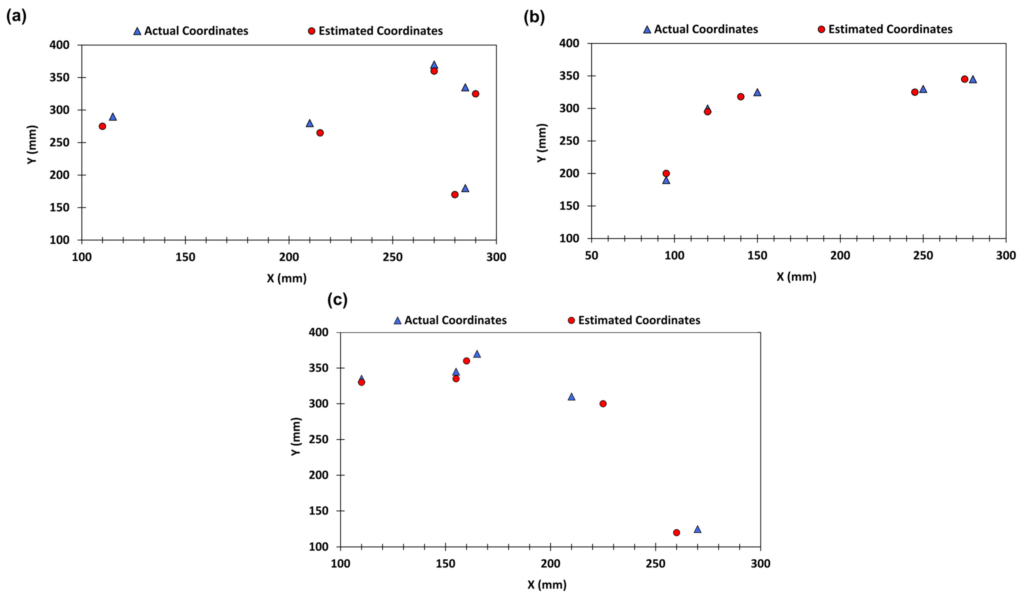
The accuracy of the visual servoing method was assessed by strategically placing a PCB at various random positions while maintaining a constant distance between the PCB and the camera. To ensure data reliability, three datasets were collected from trials conducted at different fixed depths: 230 mm, 280 mm, and 350 mm, as mentioned in
Table 3. These datasets were subsequently plotted for comparative analysis, as illustrated in
Figure 4.
3.1.1. Trial 1 Conducted at a Fixed Depth of 230 mm
The first trial was conducted with the camera positioned at a fixed depth of 230 mm from the PCB. The visual servoing method performance was evaluated based on the data presented in
Table 4. The real-world coordinates (Rx, Ry, Rz) and the estimated coordinates (Ex, Ey, Ez) were compared to assess the accuracy of the method. The deviations (Dx and Dy, respectively) between the real-world and estimated coordinates revealed minor inaccuracies. Specifically, the mean absolute error in the X coordinate was found to be 3.0 mm, while the Y coordinate exhibited a mean absolute error of 12.0 mm. These errors suggest that while the method is highly precise in estimating the X coordinate, there is a larger deviation in the Y coordinate. The analysis indicates that the visual servoing method achieved a high level of precision in the X-axis, demonstrated by the small error margins. However, the larger errors along the Y-axis indicate the need for refinement, either through improvements in the algorithm or adjustments in the calibration process, to enhance the accuracy. As illustrated in
Figure 4a, the visual servoing method shows strong potential for precise X-axis positioning as well as indicating the areas for improvement in Y-axis estimation.
3.1.2. Trial 2 Conducted at a Fixed Depth of 280 mm
The second trial, conducted at a fixed depth of 280 mm from the camera to the PCB, provided insights into the performance of the developed method at a different depth, as shown in
Table 4. The analysis of the real-world and estimated coordinates revealed mean absolute errors of 4.0 mm in the X coordinate and 5.4 mm in the Y coordinate. The decrease in Y-axis error compared to Trial 1 suggests a notable improvement in the precision of the method at this depth. The reduced errors in both X and Y coordinates indicated that the visual servoing method is more accurate at this depth, with a significant improvement in Y-axis precision. The results, illustrated in
Figure 4b, highlight the robustness and adaptability of the method, which demonstrates its capability of providing precise coordinate estimation across different depths. The consistent accuracy across measurements suggests that the method benefits from better calibration and efficiency at this depth, making it suitable for varied real-world applications.
3.1.3. Trial 3 Conducted at a Fixed Depth of 350 mm
The third trial, performed at a fixed depth of 350 mm from the camera, further evaluated the visual servoing method. The results, detailed in
Table 4, revealed mean absolute errors of 6.0 mm in the X coordinate and 8.0 mm in the Y coordinate. These errors are slightly higher than those observed in Trial 2, indicating potential challenges in maintaining precision at greater depths. Despite the increased errors, the method demonstrated reasonable precision, with consistent results across different measurements. The data analysis indicates that although the visual servoing method is effective at a distance of 350 mm, further optimization is needed to reduce errors, especially along the Y-axis. These findings indicate that although the method is robust, fine-tuning is necessary to enhance its accuracy at greater depths, as illustrated in
Figure 4c. The performance of the visual servoing method across the three trials reveals several key insights, as detailed in
Table 4. First, the method consistently achieved high accuracy in the X-axis across all trials, with mean absolute errors of 3.0 mm, 4.0 mm, and 6.0 mm for trials 1, 2, and 3, respectively. This indicates a strong capability for precise X-axis positioning. The Y-axis accuracy showed significant improvement from trial 1 to trial 2, with mean absolute errors of 12.0 mm, 5.4 mm, and 8.0 mm for trials 1, 2, and 3, respectively. This trend suggests that the method can adapt well to different depths, although further optimization is required to achieve consistent precision at greater depths.
The precision and consistency of the developed method were evident from the small, consistent error margins observed across different trials and depths. The results from trial 2, in particular, highlight the potential of this method for precise coordinate estimation, demonstrating its robustness and efficiency. The overall findings indicate that while the visual servoing method is highly effective, particularly in estimating the X and Y coordinates, further calibration and refinement are necessary to optimize its performance at varying depths.
3.2. Trial 4 Conducted to Measure Execution Time
In addition to assessing the accuracy of the visual servoing method, the execution time required for the SCARA robot to move from its initial position to the target destination was evaluated. The data obtained from Trial 4, as presented in
Figure 5, provides an analysis of the execution time of the robot at fixed depths of 230 mm, 280 mm, and 350 mm. These data provide insights into the performance and efficiency of the SCARA robot under various conditions.
At a fixed depth of 230 mm, the execution times varied between 9.19 and 13.11 s, demonstrating a narrow range that reflects consistent and efficient movement. This minimal fluctuation highlights the robustness of the mechanical design and the effectiveness of the closed-loop feedback system. It maintains precise control at a depth of 280 mm, and execution times varied more widely, ranging from 6.82 to 14.78 s. This broader range indicates that travel distance and path complexity had a more significant impact on execution time at this depth, where rapid movements (minimum of 6.82 s) were observed alongside more time-consuming tasks (up to 14.78 s). Execution times at 350 mm ranged from 5.04 to 12.16 s, indicating the fastest movements recorded. The quick execution time, particularly the 5.04-s minimum, suggests that the robot maintains high efficiency even at greater depths. However, the upper bound of 12.16 s demonstrates that increased travel distance and task complexity still influence the duration, albeit to a lesser extent.
Comparatively, the execution time data reveal that the SCARA robot maintains high efficiency and consistency across different depths. The minimal variations at 230 mm and 350 mm depths underscore the reliability of the system, whereas the wider range at 280 mm depth suggests that complexity and distance introduce more variability. The depth and travel distance significantly influence execution time, but the precise mechanical design and industrial-grade servo motors with closed-loop feedback systems ensure accurate and rapid positioning. These findings highlight the substantial potential of the system for industrial applications requiring high accuracy and swift movements within a defined workspace.
3.3. Trial 5 Conducted Using Laser Triangulation for Depth Estimation
Trial 5 was conducted to comprehensively evaluate the accuracy of the laser triangulation-based depth perception method using a single camera. A series of data presented in
Table 4 was obtained from the SCARA robot while maintaining fixed positions along the X and Y axes, isolating the depth measurement to ensure the accuracy of the depth estimation algorithm. A PCB with known depth values was used for comparison with the depth values estimated by the algorithm. These known values were then compared with the values generated by the depth estimation algorithm developed for the aforementioned depth perception method. This provided a direct evaluation of the accuracy of the algorithm. Moreover, a Vernier caliper served as a secondary depth measurement tool for validation purposes. This independent measurement enhanced confidence in the evaluation and assisted in identifying potential systematic biases in the laser triangulation setup.
The dataset from
Table 5, supplemented by the graph in
Figure 6, provides a descriptive visualization of the performance of the depth perception method. The individual accuracy values for each measurement show consistently high accuracy, with values ranging from 99.2% to 100%. This high level of accuracy is maintained across a range of depths from 200 mm to 400 mm, underscoring the robustness of the method over varying distances.
Figure 6 depicts the measured depth values against the actual depth values, highlighting the minimal offsets between them. The deviations between the actual and estimated depth values generally remained within 1–3 mm, reflecting the high accuracy of the method. The consistent pattern observed in the graph indicates that the method can reliably maintain high precision across the entire range of measured depths. A slight variation, up to 3 mm, is observed as the depth increases. This variation can be attributed to the laser pattern becoming smaller as the height increases, which presents potential challenges to the ability of the developed machine vision algorithm to calculate the accurate depth. Addressing this issue involves utilizing a higher-resolution camera to enhance the capability of the system to capture finer details of the laser pattern. Additionally, adjusting parameters within the laser triangulation algorithm can help maintain high accuracy across the entire range of depths. Fine-tuning these parameters will ensure that the method remains effective at various depths.
The average accuracy across all depth measurements is approximately 99.48%, which reveals the exceptional performance of the developed depth perception method integrated with the laser triangulation method in estimating the depth of objects. This outstanding performance highlights the suitability and effectiveness of the laser triangulation method for precise depth perception tasks, even in dynamic environments. The overall results indicate that the laser triangulation-based depth perception method is robust, precise, and capable of maintaining high accuracy across a range of depths, making it a reliable tool for depth perception in various applications.
Although laser triangulation provides high precision for depth estimation, it has certain limitations that can affect accuracy under specific conditions. One major challenge is highly reflective PCB surfaces can cause laser scattering and glare, leading to incorrect depth readings. Since PCB components often have metallic finishes, reflections can distort the laser triangulation measurements. To mitigate this, the system incorporates image masking and color filtering to isolate laser points from background noise. Additional improvements, such as using polarizing filters or matte coatings, could further enhance measurement accuracy by reducing reflection-induced errors. Changes in ambient lighting can significantly influence laser triangulation performance. Bright or inconsistent lighting conditions may interfere with the ability of camera to detect laser points, causing fluctuations in depth estimation. To counteract this, the experiment was conducted in a enclosed environment. Future enhancements could include controlled ambient lighting environment, adaptive exposure settings, or HDR imaging to compensate for varying lighting conditions dynamically. Laser triangulation accuracy is also dependent on the angle of incidence on non-flat surfaces. If the PCB has irregular or curved components, the displacement of laser points may not follow a linear regression model, leading to errors in depth estimation. Implementing AI-based filtering techniques or deep learning models to refine depth measurements could improve accuracy in such cases. Despite these limitations, laser triangulation remains a practical and cost-effective solution for real-time depth estimation in PCB repair applications. Future research will focus on further refining calibration techniques and integrating additional vision-based correction mechanisms to enhance overall system performance.
The system was successfully implemented on a laptop with an Intel Core i5 processor and 16GB of RAM, achieving an average processing speed of 16 frames per second while running MATLAB and Simulink. However, MATLAB is not strictly required, as alternative frameworks like ROS2 Humble can also be used for inverse kinematics computations. For this prototype, MATLAB was selected to facilitate development and expedite implementation, ensuring efficient system performance.
While SCARA robots have been widely used for PCB component placement, their application in PCB repair remains underexplored. Repairing PCBs requires precise localization and removal of SMD components without damaging surrounding circuitry, making accurate spatial coordinate estimation essential. This study addresses this gap by achieving millimeter-level accuracy in SMD component positioning, enabling the practical deployment of SCARA robots for PCB repair. The integration of a monocular vision-based visual servoing system for X and Y coordinate estimation, combined with a laser triangulation-based depth estimation system for the Z-axis, ensures both high precision and cost-effectiveness. The system reliably tracks SMD components on a PCB, assisting an automated desoldering system in identifying and removing components. For industrial implementation, factors such as lighting conditions, operating temperatures, and PCB size variations must be considered. With minor adjustments—such as modifying SCARA arm lengths and incorporating an anti-glare lighting system—these challenges can be addressed, enabling efficient large-scale deployment.
4. Conclusions
In the present approach, a real-world coordinate estimation method for a SCARA robot using laser triangulation and visual servoing was developed to enhance precision in PCB repair automation. The system was rigorously tested across multiple trials, demonstrating its reliability and accuracy. The visual servoing method effectively estimated X and Y coordinates at depths of 230 mm, 280 mm, and 350 mm, with mean absolute errors ranging from 3.0 mm to 6.0 mm across three trials, achieving an average accuracy of 98%. Meanwhile, the laser triangulation method achieved exceptional depth estimation accuracy, ranging from 99.2% to 100% across depths of 200 mm to 400 mm, with an overall average accuracy of 99.48%. Furthermore, the system exhibited consistent execution times, emphasizing the efficiency of the SCARA robot’s design and control mechanisms in maintaining precise and rapid movements for PCB repair applications. These findings highlight the potential of integrating computer vision systems with SCARA robots for industrial automation, particularly in precision-critical tasks such as PCB manufacturing, assembly, and testing. While the current study primarily focuses on coordinate estimation, future work will explore the system’s performance in real-world soldering and desoldering operations. This includes investigating the impact of micro-movements and operational instabilities to ensure reliable component replacement in production environments. Further refinements in calibration and algorithmic optimization are expected to enhance the overall accuracy and robustness of the system. Additionally, the integration of a customized end-effector for PCB repair, incorporating tools like hot-air guns for PCB soldering and desoldering, a vacuum suction mechanism for safe component handling, and a precision grab mechanism, will be considered to expand the practical applicability of SCARA robots in industrial settings.


 ,
, 


