Communication

A Hard Copper Open X-Band RF Accelerating Structure Made by Two Halves

1
Laboratori Nazionali di Frascati, Istituto Nazionale di Fisica Nucleare, Via Enrico Fermi 54, 00044 Frascati, Italy
2
Dipartimento di Scienze di Base e Applicate per l’Ingegneria (SBAI), Università degli Studi di Roma “La Sapienza”, Via Scarpa 14, 00161 Rome, Italy
3
SLAC National Accelerator Laboratory, Menlo Park, CA 94025, USA
4
INFN/Roma1, Istituto Nazionale di Fisica Nucleare, Piazzale Aldo Moro, 2, 00185 Rome, Italy
*
Author to whom correspondence should be addressed.
Instruments 2022, 6(1), 5; https://doi.org/10.3390/instruments6010005
Submission received: 29 October 2021 / Revised: 2 January 2022 / Accepted: 12 January 2022 / Published: 15 January 2022
(This article belongs to the Special Issue Recent Advance in Particle Accelerator Instrumentation)

1. Introduction

This communication focuses on the technological developments aiming to show the viability of novel welding techniques [1,2], and related applications, in order to benefit from the superior high-gradient performance of accelerating structures made of hard-copper alloys. The technological activity of testing high-gradient RF sections is related to the investigation of breakdown mechanisms, which limit the high gradient performance of these structures. In this content, our activity consists of the design, construction and high-power experimental tests of standing-wave (SW) 11.424 GHz (X-band) accelerating cavities with different materials and methods.
The goal is to assess the maximum sustainable gradients with extremely low probability of RF breakdown in normal-conducting high-gradient RF cavities. The most common bonding techniques, used worldwide, are high-temperature brazing and diffusion bonding. Brazing and diffusion bonding are performed inside a high-temperature furnace. On the other hand, experimental results with hard copper cavities, conducted at SLAC, CERN and KEK [3,4] have shown that hard materials sustain higher accelerating gradients for the same breakdown rate. Therefore, it would be better to avoid high-temperature processing of the cavities to benefit from superior high-gradient performance of hard copper alloys.
In this framework, we conduct experiments that involve the Electron Beam Welding (EBW) and Tungsten Inert Gas (TIG) processes, which allow us to build practical, multi-cell structures made with hard copper alloys in order to increase their RF performance against soft ones. For this purpose, open structures made of two halves have been investigated and fabricated. Details on the fabrication procedure of hard copper X-band structure by using the TIG method are given in our previous paper [1].
In this paper, we present RF characterization and low-power RF tests of a two-halves split hard-copper structure [5,6] that will be consequently TIG welded and employed for high-gradient tests and for the study of the RF breakdown physics. To achieve this aim, the structure geometry that we propose (shown in Figure 1a, cavity design) allows getting a high longitudinal shunt impedance Rsh of the accelerating mode, increases the mode separation frequencies, and improves the operating vacuum level.
In addition, intense beam currents and multibunch operation are essential features, for example, for increasing the luminosity of a linear collider, but beam current wakefields and coupled-bunch mode instabilities, which mostly arise from the parasitic modes of the accelerating structures, can limit the accelerator performance. Hence, our main interest is also to detune the cavity in order to reduce the beam instability using a novel simpler technique and dedicated absorbers of higher-order modes (HOMs). The two cavity halves are aligned and clamped together by means of male–female matching surface. The clamping is obtained with stainless screws, and the cavity will be TIG welded at COMEB [7] on the outer surface. Preliminary low-power RF measurements are in agreement with the simulated ones. The estimation of mode separation is described later in this paper. The activity of fabricating a section with four quadrants is also in progress.

2. Low-Level RF Measurements

Figure 1b,c show the two halves of the X-band assembled structure under RF low-level test. It consists of three cells: the middle one is the high-gradient cell, while the first and third ones are end-cells. The peak on-axis electric field in the middle cell must be two times higher than that of the end-cells.
Figure 1a reports a sketch of a quarter of a two-half structure for the simulation studies performed with ANSYS HFSS software [8]. The simulated frequency spectrum is reported in Figure 1d, and Figure 1e shows the measured frequency spectrum obtained using two antennas. The numerical estimations of mode frequencies and the longitudinal field profile of the π -mode are in good agreement with the experimental ones.
In Table 1, we report frequencies and quality factors of the resonant modes, obtained from simulations, for the split open structure in comparison with the same cavity designed with the conventional “closed” approach.
The frequency separation between the π - π / 2 and π / 2 -0 modes is about 440 MHz and 230 MHz, respectively, in the case of the two halves structure, while it is equal to about 435 MHz and 225 MHz for the closed one. The two-halves structure cell-to-cell coupling coefficient is estimated to be 6.1%, while the one for the other structure is 6%. It is important to notice that the value of the frequency separation of each mode is proportional to the cavity form factor Rsh/Q [9], with Rsh the shunt impedance of the mode, which depends on the cell-to-cell coupling coefficient. In addition, from a comparison between the two halves structure and the closed one, we also observe that the frequency separation is wider in the case of the two-halves structure, since the capacitive effect is stronger with respect to that of the closed cavity. In particular, the 0-mode of the open cavity is the most affected with a deviation 11 MHz greater with respect to the homologous separation in the closed one. By increasing the number of splittings, it is possible to further increase the mode frequency separation accordingly.
As additional information, the frequency separation for this structure is shown to be 25% larger than the one achieved in other standard brazed structures [10] with a rough hard edge geometry but without splitting [10]. The measured quality factor of the π mode of the two-halves structure, obtained by using two antennas, is about Q ∼ 6900, which is 30% lower than the numerical predictions due to the relatively poor electrical contact during low-power measurements. Our next step is to repeat the RF characterizations after having welded the two halves and also by using the input power mode launcher.
We have also scheduled the construction of another structure made of four quadrants in order to confirm the expected wider amount of mode frequency separation. Moreover, for reasons related to both the feasibility of the hard copper structure and a high shunt impedance, we believe that we need to find a compromise between the amount of detuning effects and the number of structural subdivisions. This approach can be extended to the cavity resonators used in circular accelerators, in order to eliminate or strongly reduce the longitudinal coupled-bunch instability associated with the accelerating mode.

3. Possible Applications of Split Open Structures

The next generation of accelerators is highly demanding in terms of maximizing accelerating gradients, minimizing overall machine length and cost, improving the beam quality, reducing beam loading effects, and so on. In the case of circular accelerators, one important mechanism that produces beam instability and power losses consists in the possibility of the charged particles to excite high-order resonant fields in RF accelerating cavities when passing through them. This is possible only for those accelerating structures with resonant modes in frequency ranges that overlap the beam Fourier spectrum. If the beam loading on a large electron/positrons storage ring is strong, the accelerating mode of a normal conducting cavity gives rise to coupled-bunch instability.
Additionally, in recent years, we have seen a revolution in high-brightness electron beams because of the maturation of RF photo-injector performance. In order to improve the electron beam brightness, larger mode separation is also needed. Furthermore, in pre-buncher and chopper cavities of linear accelerators operating at high currents, an RF detuning is required to reduce the interaction with higher-order modes, which affect the beam quality. These problems can be cured by using the split open structure approach, which also provides the possibility of improving the vacuum level of a factor of at least ten with respect to the usual solution by inserting an additional vacuum chamber connected to the beam pipe. For a fixed geometry of the structure (which means a fixed form factor ratio Rsh/Q) and for a given beam current and cavity peak voltage, the frequency detuning effect can be determined, for example, as shown in [9]. Intense investigations on the absorbers for damping higher order modes, are also in progress.

4. Conclusions

In very high brightness accumulation rings or linacs, a longitudinal coupled bunch instability can also arise from the cavity acceleration mode. To solve this problem, an increase in the RF cavity bandwidth for the detuning frequency is requested. The optimized cavity design made with quadrants allows us to increase the frequency separation of longitudinal modes and provides a high longitudinal shunt impedance of the operating mode. In addition, by using TIG technology to make a hard copper structure, we are able to improve the vacuum level by one or two orders of magnitude. As a final comment, studies are also underway for HOM damping.

Author Contributions

B.S., V.D. and L.F. performed the RF design of the two-halves structure and technological development; F.C., M.C., L.F. and B.S. carried out the low-power RF characterization of the structure; M.B., M.M. and L.P. developed the preliminary approach on the HOMs estimation. All authors contributed to write the article, discussed it as well as approved the submitted version. All authors have read and agreed to the published version of the manuscript.

Funding

This work was partially supported by the Commettee V of the INFN.

Institutional Review Board Statement

Not applicable.

Informed Consent Statement

Not applicable.

Data Availability Statement

Data sharing is not applicable to this article as no data sets were generated or analysed during the current study.

Acknowledgments

The authors would like to thank James Rosenzweig from UCLA for their useful discussion and helpful advice.

Conflicts of Interest

There are no conflicts of interest.

References

  1. Dolgashev, V.A.; Faillace, L.; Spataro, B.; Bonifazi, R. Innovative compact braze-free accelerating cavity. J. Instrum. 2018, 13, P09017. [Google Scholar] [CrossRef]
  2. Dolgashev, V.A. High gradient, x-band and above, metallic rf structures. In Proceedings of the 2nd European Advanced Accelerator Concepts Workshop (EAAC 2015), Isola d’Elba, Italy, 12–19 September 2015. [Google Scholar]
  3. The Compact Linear Collider (CLIC). Available online: https://home.cern/science/accelerators/compact-linear-collider (accessed on 11 January 2022).
  4. Dolgashev, V.; Faillace, L.; Spataro, B.; Tantawi, S.; Bonifazi, R. High-Gradient RF Tests of Welded X-band Accelerating Cavities. Phys. Rev. Accel. Beams 2021, 24, 081002. [Google Scholar] [CrossRef]
  5. Hao, Z.; Grudiev, A. Design of the Compact Linear Collider main linac accelerating structure made from two halves. Phys. Rev. Accel. Beams 2017, 20, 042001. [Google Scholar]
  6. Zha, H.; Grudiev, A.; Dolgashev, V.A. RF design of the CLIC structure prototype optimized for manufacturing from two halves. In Proceedings of the 6th International Particle Accelerator Conference (IPAC 2015), Richmond, VA, USA, 3–8 May 2015. [Google Scholar]
  7. Comeb. Available online: http://www.comeb.it/ (accessed on 11 January 2022).
  8. Ansys. Available online: https://www.ansys.com/ (accessed on 11 January 2022).
  9. Geer, C.A.J.; Bakker, R.J.; der Meer, A.F.G.; Amersfoort, P.W.; Gillespie, W.A.; Saxon, G. Bunching of an intense electron beam extracted from a triode gun modulated at 1 GHz. Nucl. Instrum. Methods Phys. Res. Sect. A 1991, 307, 553–561. [Google Scholar] [CrossRef]
  10. Spataro, B.; Alesini, D.; Chimenti, V.; Dolgashev, V.; Haase, A.; Tantawi, S.G.; Higashi, Y.; Marrelli, C.; Mostacci, A.; Parodi, R.; et al. Technological issues and high gradient test results on X band molybdenum accelerating structures. Nucl. Instrum. Methods Phys. Res. A 2011, 657, 114–121. [Google Scholar] [CrossRef]
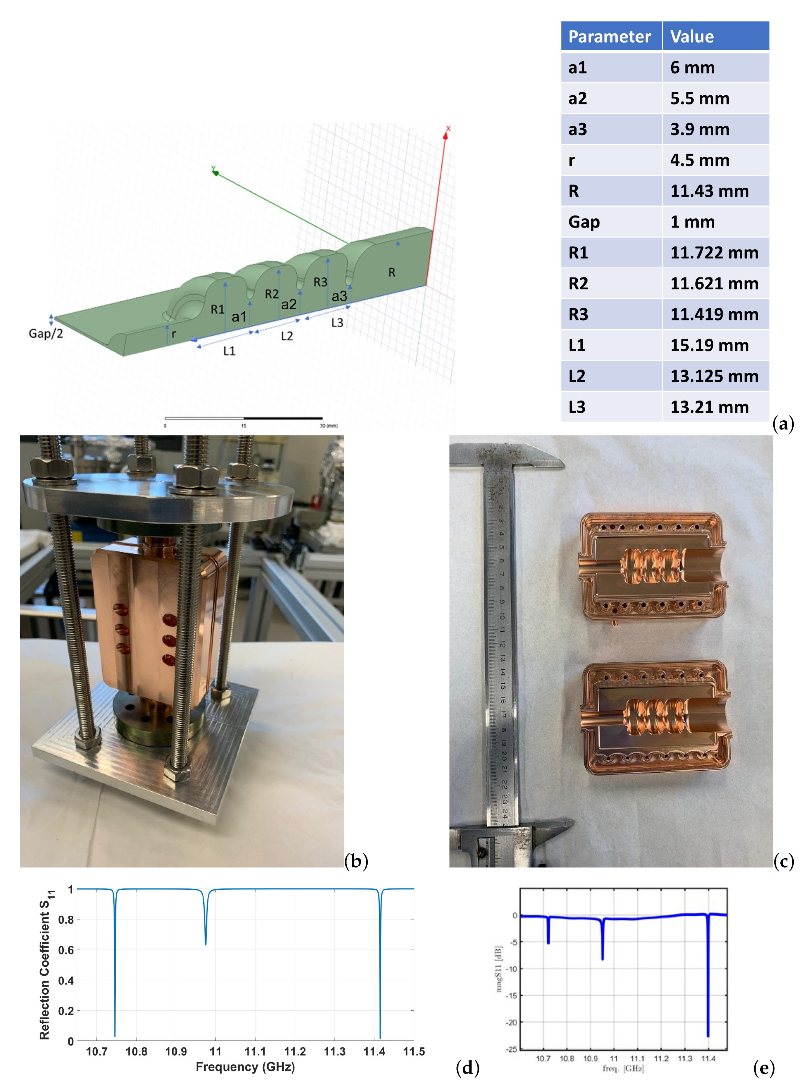
Figure 1. Picture of the two halves structure under test. (a) Sketch of one quarter of two half structures for simulation studies using ANSYS HFSS software (b) clamped structure for low-power tests; (c) two halves of the machining; (d) simulated structure frequency spectrum (e) measured frequency spectrum.
Instruments 06 00005 g001
Table 1. Comparison between mode frequencies and quality factors for the closed structure and two-half structure.
ModeFrequency [MHz]Frequency [MHz]Quality Factor (Q)Quality Factor (Q)
(Two Halves)(Closed Structure)(Two Halves)(Closed Structure)
010,74910,76010,52010,615
π / 2 10,97910,98410,21310,306
π 11,41811,42010,51210,610
Publisher’s Note: MDPI stays neutral with regard to jurisdictional claims in published maps and institutional affiliations.

