Abstract
Plasma wakefields driven by high power lasers or relativistic particle beams can be orders of magnitude larger than the fields produced in conventional accelerating structures. Since the plasma wakefield is composed not only of accelerating but also of decelerating phases, this paper proposes to utilize the strong decelerating field induced by a laser pulse in the plasma to absorb the beam energy, in a scheme known as the active plasma beam dump. The design of this active plasma beam dump has considered the beam output by the EuPRAXIA facility. Analytical estimates were obtained, and compared with particle-in-cell simulations. The obtained results indicate that this active plasma beam dump can contribute for more compact, safer, and greener accelerators in the near future.
1. Introduction
Laser wakefield accelerators (LWFAs) [1,2] greatly benefited from recent advances in laser technology [3,4,5]. State-of-the-art facilities utilise high peak-power, ultrashort laser pulses propagating along gas-filled capillaries, for producing high-quality, multi-GeV electron beams within a few centimeters of propagation [6,7,8]. Such compactness might enable the design of the so-called table-top accelerators, which could be used, for example, in future transportable LWFA-based applications [9,10]. In addition, the serial coupling of multiple LWFA stages [11] can potentially overcome the limitation imposed by the laser-energy depletion [2]. This process, also known as staging, might allow for scaling the LWFA technology from GeV to TeV level, as discussed in preliminary theoretical studies on the design of a laser-plasma-based linear collider [12,13]. However, further development is required for taking full advantage of these unique LWFA properties.
An important initiative towards maturing LWFA technology is the European Plasma Research Accelerator with Excellence in Applications (EuPRAXIA), a unique collaboration of multiple laboratories funded by the European Union. The EuPRAXIA project aimed to design a multi-GeV plasma-based electron accelerator, capable of producing high-quality beams with industrial robustness. The conceptual design of EuPRAXIA stands for an ultra-compact, scalable accelerator for science, industry, medicine or the energy frontier. One of the many topics covered in the EuPRAXIA Conceptual Design Report [14] is the electron beam dump. The aforementioned compactness, which could lead to the development of transportable LWFA applications, might be limited by the bulk beam dump required for the safe disposal of high-energy beams after their use, if conventional technology is adopted.
Relying on beam and dense-matter interaction, conventional beam dumps are carefully designed to mitigate radioactivation hazards [15]. However, beam dump requirements such as its size, volume, and cost keep increasing as new accelerators are designed to provide high-energy and high-power beams. Recently, plasma beam dumps (PBD) have been proposed as a safe alternative for decelerating high-energy beams over distances that are orders of magnitude shorter than that in a conventional beam dump [16,17]. In this scheme, rather than converting the beam kinetic energy in thermal heating and radiation through collisions, deceleration is achieved by using collective forces in low-density plasmas. As a consequence, hazardous radioactivation is significantly reduced. Moreover, unlike the heating produced in conventional beam dumps, in a PBD most of the beam energy is deposited into the plasma as organised electron oscillations, which may be recoverable [18,19]. Therefore, besides being safer and more compact, PBDs might be soon a greener option if compared to conventional beam dumps.
Two PBD types, the passive and the active schemes, have been proposed [16,17]. In the first, an electron beam propagating in an undisturbed plasma is decelerated by its self-driven wakefield. Since this self-generated wakefield, which rises from zero at the beam head, is not homogeneous along the beam, the beam-energy extraction is strongly chirped in the passive PBD. Particles experiencing a high-amplitude wakefield are decelerated earlier, dephasing and reaching an accelerating laser-wake phase. At this point, re-acceleration of such particles saturates the net beam-energy extraction. The aforementioned behaviour has been experimentally demonstrated [20].
In order to prevent re-acceleration (and thus saturation of the beam-energy extraction), the use of alternating plasma and vacuum regions, as well as the insertion of periodic thin foils in a homogeneous plasma, were proposed as mechanisms to remove the decelerated electrons [16]. In addition, tailored plasma-density profiles, shaped to transversely eject the decelerated electrons before their re-acceleration, have also been presented as a more feasible alternative [21,22,23]. However, due to the passive nature of this scheme, there is no direct control over the intensity of the decelerating gradient, other than setting and/or tailoring the plasma density profile [21,22,23].
The aforementioned limitations can be mitigated by adding a laser pulse preceding the beam, thus implementing the active PBD. In this scheme, the laser spatial profile and its relative phase with respect to the beam can be used to control the laser-driven wakefield in the plasma, hence the net wakefield along the beam. As previously shown [17], a flattened, higher-amplitude net wakefield can be obtained in the active PBD. This allows for a more effective beam-energy extraction, with a residual energy chirp, over a shorter propagation distance if compared to the passive case.
The goal of this work is to propose an active PBD for a 1 GeV EuPRAXIA beam. In a previous work [23], a passive PBD was proposed for such beam, which could in principle be used to extract nearly 90% of the beam kinetic energy, within ∼16 cm of propagation in plasma. However, besides requiring a tailored plasma density profile, the implementation of such passive PBD scheme would also require a cylindrical, material shielding to stop transversely ejected particles with average energies of ∼150 MeV. As it will be shown, in the active PBD here presented, approximately 96% of the total beam-energy is extracted within a simultaneously decelerating and focusing phase of the net wakefield, hence no high-energy particles are ejected. Moreover, the beam energy is extracted over a shorter distance, with an extremely reduced chirp if compared to the passive PBD.
This paper is organized as follows. In Section 2, an analytical description for the active PBD is shown. In this section, the net wakefield produced by the superposition of the beam and laser individual wakefields is discussed. In addition, the analytical expression for the evolution of the total beam-energy in the active PBD is presented. In Section 3, particle-in-cell (PIC) simulations are carried out for a 1 GeV EuPRAXIA beam undergoing the designed active PBD. Numerical results for the total beam-energy loss in the active PBD are compared to analytical estimates, and an extended discussion is performed. Finally, in Section 4, the main conclusions of this work are summarised, and a brief discussion on additional topics such as the plasma heating and radiation emission, is presented.
2. Active Plasma Beam Dump Modelling
An active PBD consists of a beam propagating in a plasma, experiencing the decelerating phase of a laser-driven wakefield, as briefly discussed in Section 1. Therefore, it can be thought of as a laser wakefield accelerator (LWFA) operating with an external beam injected within a decelerating phase of the laser wake. Hence the same beam loading techniques [2], adopted to minimize the energy chirp in an LWFA, can be applied to the active PBD scheme. In the linear regime, the net longitudinal wakefield along the beam can be obtained by superimposing the wakefields that would be individually produced by the beam and laser pulse, and , respectively. This effect is illustrated in Figure 1 as follows.
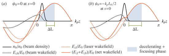
Figure 1.
Beam density (solid black line), beam wakefield (dashed black line), laser wakefield (dashed red line), and net wakefield (solid red line) for (a) , and (b) . In this figure, the beam propagates in the plasma from left to right, and is the distance between the beam head and the end of the simultaneously decelerating and focusing phase (light-blue-filled region).
Figure 1 shows the beam and the wakefields at the initial state , in which the propagated distance is . The laser pulse was omitted for simplicity, and the beam propagates from left to right. By comparing both panels, one can see how the net wakefield is affected by changing the beam centroid. Rather than evaluating the initial phase between both individual wakefields, for practical purposes the initial relative phase between a reference point of the laser wakefield and the beam tail is considered. As previously done [17], this reference point is set at the beginning of a simultaneously decelerating and focusing laser-wake phase (light-blue-filled region), which has a length of , where is the plasma wavelength, for a wakefield excited in the linear regime [2]. Then, for the beam is loaded within the laser wakefield as shown in Figure 1a. In addition to the spatial arrangement for , panel (a) also depicts the on-axis beam density profile (solid black line), the beam wakefield (dashed black line), the laser wakefield (dashed red line), and the net longitudinal wakefield (solid red line). The beam density is re-scaled by the uniform plasma density , and the wakefields are re-scaled by the non-relativistic cold electric field wave-breaking amplitude , where c is the speed of light in vacuum, and e are the electron mass and charge, respectively, is the plasma frequency, and is the vacuum permittivity. Moreover, panel (a) also shows the distance between the beam head and the end of the simultaneously decelerating and focusing laser-wakefield phase, . As it will be discussed, due to the dephasing between the beam and laser wake, has to be taken into account when setting the active PBD parameters. Panel (b) shows the same quantities, now plotted for an initial phase , where is the plasma angular wavenumber, and is the beam longitudinal length. As it will be later presented (see Equation (3)), for a Gaussian beam , where is the beam longitudinal RMS length. For this initial phase, , the beam centroid (rather than its tail) is placed at the beginning of the decelerating wakefield phase. Although for this configuration the beam tail starts within an accelerating laser-wake phase, this choice provides a longer distance , hence a longer dephasing length, as it will be soon addressed.
From Figure 1a, one can clearly understand the advantages of the active PBD over the passive scheme. Within the beam, while the self-driven wakefield (dashed black line) rises from zero at its head, the laser wakefield (red dashed line) is maximum at this position, decreasing to zero at a similar rate if proper parameters (laser pulse amplitude and duration, initial phase) are chosen. This compensation causes the net wakefield (red solid line) to be flattened along the beam, allowing for a beam-energy extraction with a greatly reduced energy chirp. In addition, since the net wakefield has a higher amplitude than that of the beam-driven wakefield, the beam energy is extracted over a shorter distance in the active PBD, if compared to the passive PBD scheme. In Figure 1b, despite the less-flatten, lower-amplitude net wakefield, this choice of initial phase allows for a longer propagation, improving the beam-energy extraction before the beam head reaches the end of the simultaneously decelerating and focusing laser-wake phase (light-blue-filled region).
Since the laser pulse propagates in the plasma with a group velocity , the high-energy electrons from the beam under deceleration, propagating with , will eventually outrun the simultaneously decelerating and focusing phase of the net wakefield, in a process known as dephasing. Therefore, the design of an active PBD has to ensure that the beam energy is extracted within the aforementioned region. The dephasing length is usually defined as the propagation distance at which a single electron will outrun the laser wake by a distance of [2]. However, in order to prevent early defocusing of particles at the beam head, the beam longitudinal length and its initial phase shall be taken into account when estimating the dephasing length . In other words, will be the propagation distance at which the beam head outruns the distance shown in Figure 1. By solving , where , and is the plasma wakefield phase velocity [2], the following solution can be obtained,
if , where is the Lorentz relativistic factor associated with the wakefield phase velocity. In order to evaluate , an analytical estimate of , derived by Benedetti et al. [24], is adopted. Such estimate assumes the propagation of a mildly relativistic () Gaussian laser pulse in a matched transverse parabolic plasma channel [2], chosen to flatten the net wakefield along the beam.
In order to obtain an analytical expression for the evolution of the total beam-energy in an active PBD, the following assumptions are now considered. Despite the matched transverse parabolic plasma-density profile, adopted to prevent the laser pulse diffraction, the plasma is assumed to be homogeneous, with density . The evolution of both the laser pulse and beam-density profile is neglected. For the laser, this is reasonable due to the matched propagation in an underdense plasma, for a distance much shorter than the laser pump depletion [2,24]. For the beam, the frozen density-profile assumption holds well while the beam remains highly relativistic [17]. If the aforementioned assumptions are considered, and if analytical expressions are available for the laser and beam-driven wakefields, and , then the total beam-energy can be obtained as a function of the propagation distance s, and the initial relative phase . Assuming a half-sine longitudinal and parabolic transverse beam-density profile, and a longitudinal Gaussian and transverse parabolic laser pulse profile, the following expression for the total beam-energy evolution has been derived [17],
In Equation (2), is the initial total beam energy, s is the propagation distance, is the previously discussed initial relative phase, is the peak beam-density, and are the Lorentz relativistic factors associated with the laser group velocity and beam initial velocity , respectively, is the amplitude of the laser-driven wakefield, and is the laser waist. Moreover, and are the length of a longitudinal half-sine and the radius of a transverse parabolic beam density distribution, respectively.
Although Equation (2) was developed for a half-sine longitudinal and parabolic transverse electron beam distribution [25], it can be used to estimate the total beam-energy loss of a Gaussian electron beam, if the following matching conditions between both distributions [26] are adopted,
where and are the longitudinal and transverse RMS sizes, respectively.
3. An Active Plasma Beam Dump for Eupraxia Beams
Building upon previous studies on the passive PBD scheme [23], a design for an active PBD for an 1 GeV EuPRAXIA beam is now presented. The complete set of beam parameters is displayed in Table 1. Such values characterize a typical EuPRAXIA output beam [27]. Regarding the laser, a Gaussian pulse is adopted, with longitudinal RMS length and waist . While the laser longitudinal RMS length is chosen to meet the resonant condition with the plasma wakefield [2], the laser waist is set to be much larger than the electron bunch transverse size. In addition, the laser wavelength is , and the normalised laser strength is .

Table 1.
EuPRAXIA electron bunch parameters adopted in the simulations.
When choosing the active PBD laser and plasma parameters, the following constrains must be taken into account. The plasma density has to be low enough to allow for the beam energy to be fully extracted before it experiences a dephasing of a quarter of the plasma wavelength, which is approximately the length of the simultaneously decelerating and focusing laser-wakefield phase. Yet, the choice should prevent the normalised beam-density peak from becoming too high, in order to ensure the validity of the analytical model (ideally, ). Regarding the laser intensity, its normalised strength parameter is chosen to flatten the net wakefield along the beam. Large values of (e.g., ) should be avoided in order to prevent the wakefield excitation to occur in the nonlinear regime [2]. The breaking of the bubble structure may lead to background plasma electrons being injected and accelerated in the rear part of the bubble. This should be avoided, since the active PBD is intended to decelerate an externally injected electron beam. On the other hand, the laser intensity cannot be too small (e.g., ), otherwise a linear plasma wakefield with small field amplitude will be generated. This will compromise the advantage of compactness, expected for an active PBD.
The plasma density and laser intensity can be chosen with aid of Equation (2). Since this equation includes the dynamics of beam dephasing, it is possible to observe if, for a given set of parameters, the total beam-energy will be extracted before reaching an accelerating laser-wake phase. In addition, by numerically solving , the theoretical propagation distance at which the total beam-energy will be extracted, , can be determined. Since Equation (2) was derived under the assumption that the beam density distribution does not evolve, which only holds while the beam remains highly relativistic, and because the beam-energy extraction in an active PBD still has a residual chirp, the zero-energy at is not attainable. Yet, provides a useful estimate for the active PBD deceleration length. A proper choice of plasma density requires to be shorter than the dephasing length , estimated for the same density by using Equation (1).
Figure 2, plotted for a plasma density of , shows (blue line) as a function of the initial phase . In addition, the dephasing length (red line) shows for the same range of how long the beam can propagate before dephasing from a focusing (green-filled region) to a defocusing (red-filled region) laser-wake phase. In this figure, two initial phases, and , are marked (black dashed lines). These initial phases, which are explained in Figure 1, are adopted along this work.
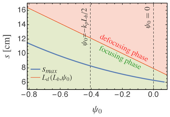
Figure 2.
Theoretical maximum propagation distance and dephasing length , plotted as a function of the initial phase for an EuPRAXIA 1 GeV beam ().
It is worth noting that, for , the peak beam-density is . Since , the wakefield excited by such a beam is not expected to be within the linear regime, as assumed when deriving Equation (2). Moreover, this equation for was derived assuming a well-defined half-sine longitudinal beam-density profile, rather than a Gaussian, which has infinitely long tails. Hence, as the beam head approaches the defocusing region of the laser-wake due to dephasing, a departure between the total beam-energy obtained from analytical estimates and PIC simulation results is expected.
Particle-in-cell simulations in a quasi-3D geometry were performed by using the FBPIC code [28]. Although particles in FBPIC have 3D Cartesian coordinates, this code adopts a spectral solver, which uses a set of 2D radial grids, each of them representing an azimuthal mode m. The mitigation of spurious numerical dispersion by the spectral solver algorithm, including the zero-order numerical Cherenkov effect [29], and the adoption of the openPMD meta data standard [30] are among the many interesting FBPIC features. In this work, two azimuthal modes were used to model the active PBD. The first mode, , represents axisymmetric fields, i.e., fields with cylindrical symmetry, with no dependence on the azimuthal angle . The second mode, , is added in order to model a linearly polarised laser in the x-direction. The simulation domain is , where is the co-moving coordinate, and , where x and y are the transverse coordinates. The longitudinal and transverse resolutions are and , respectively, and the total number of particles per cell is 16, 2 being along the longitudinal coordinate z, 2 along the radial coordinate r, and 4 along the azimuthal angle .
Considering the aforementioned physical and numerical parameters, two PIC simulations, with distinct initial phases, were performed. While for the beam tail is initially placed at the beginning of a decelerating laser-wakefield phase, for the beam centroid is placed at such position. As mentioned in Section 2, although for this choice the beam tail starts the simulation within an accelerating laser-wake phase, it allows for the beam head to cross a longer distance while dephasing (as shown in Figure 1). In Figure 3, panels (a) and (b) show the net longitudinal wakefield (color scale) for both phases, and , respectively, plotted at . Moreover, the on-axis outlines (purple lines) show how the net wakefield is affected by the distinct values of . The observed behaviour is in agreement with the prior discussion on the superposition of the individual wakefields presented in Section 2, and depicted in Figure 1.
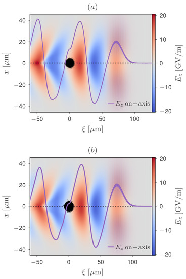
Figure 3.
Net longitudinal wakefield (color scale) at , plotted for (a) , and (b) ; the on-axis outlines (purple lines) show how the net wakefield is affected by loading the beam (black dots) at the aforementioned initial phases.
Figure 4 depicts the evolution of the normalised total beam-energy , obtained from two PIC simulations (solid lines) performed with identical parameters, except for their initial phases. In addition, analytical estimates (dashed lines) obtained by using Equation (2) are also provided. For , the minimum total beam-energy achieved in the PIC simulation (solid red line) is . In other words, the active PBD extracted approximately 94% of the total beam-energy, within a propagation distance of . Beyond this distance, decelerated electrons quickly dephase to the prior accelerating laser-wake phase, gaining energy and causing to increase. For the same initial phase, the analytical estimate (red dashed line) predicts a complete beam-energy extraction . Since the PIC simulation result for overlaps its analytical estimate for , this difference might have been caused by the excessive proximity between the beam head and the defocusing laser-wake phase, as mentioned earlier in this section. For , while the PIC simulation (solid blue line) shows a minimum of , the analytical estimate (blue dashed line) for the same initial phase predicts . From Figure 2, it can be seen that, for this initial phase, the distance between and the corresponding dephasing length is larger than that obtained for . Since for the beam head remains reasonably far from the defocusing phase, a better agreement is observed between the PIC simulation result and the analytical estimate for the total beam-energy evolution . Moreover, a slightly lower minimum value of is observed for this initial phase.
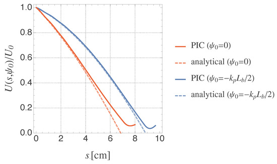
Figure 4.
Beam total energy loss, active PBD (1 GeV beam).
Besides being able to extract most of the total beam-energy, achieving this with a small, residual energy chirp is one of the reasons why this scheme has been proposed [25]. As shown in Figure 5, plotted for the simulation with at , and Figure 6, plotted for the simulation with at , such feature has been accomplished for both investigated cases. In Figure 5, panel (a) displays the beam phase space for , the propagation distance at which the minimum total beam-energy is achieved for . The arrange of particles shown in this panel, with charge density represented by a color scale, can be explained as follows. The reasonably dense cluster of particles located at , showing a positive, linearly-rising energy chirp from 0 to ∼0.2 GeV, corresponds to the beam head. Since for this initial phase the whole beam length is accommodated within the simultaneously decelerating and focusing phase, the effective dephasing region is shortened. Hence, the energy from particles at the beam head cannot be fully extracted before they reach the defocusing phase, at which they gain energy due to transverse acceleration. The second high-density cluster of particles, located at , is a re-acceleration peak formed by previously decelerated particles, which are dephased once they are no longer highly relativistic. As soon as these particles reach a prior accelerating phase of the laser wake, they start gaining energy, thus getting phase-locked and remaining at that position. The quasi-vertical, slightly tilted low-density line of particles seen within is formed by particles from the original beam tail. Since for the tail is placed at the beginning of a laser-wake decelerating phase, particles closer to the tail experience a lower-amplitude decelerating field than those located at the beam body and head. Since the particle density gets lower towards a Gaussian tail, a small, decreasing fraction of particles from the beam tail retain up to ∼40% of their initial energies, forming a fainting line in the beam phase space. In Figure 5b, the energy spectrum and its cumulative distribution function (cdf) show that, at this propagation distance, most of the beam particles have less than 10% of their initial energy (). However, the residual energy chirp observed in panel (a) causes an appreciable energy dispersion in the energy spectrum plotted in panel (b).
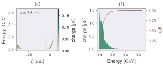
Figure 5.
(a) Beam phase space, and (b) energy spectrum with its cumulative distribution function (cdf), both plotted for at . At this propagation distance, .
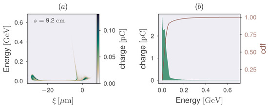
Figure 6.
(a) Beam phase space, and (b) energy spectrum with its cumulative distribution function (cdf), both plotted for at . At this propagation distance, .
Following a previously adopted optimization technique [25], the initial phase in the second simulation is changed from to , aiming to increase the effective dephasing region in order to enhance the energy extraction at the beam head. Indeed, this was achieved, as it can be seen by inspecting the lower-right corner of Figure 6a. In this plot, the cluster of particles located at has a higher density and a much lower energy chirp, if compared to the previous phase space shown in Figure 5a. In addition, a higher density of particles located at the re-acceleration peak (lower-left corner) is also observed for , with a residual energy chirp similar to that observed for the previous case (). However, since for this initial phase the beam tail is initially placed at an accelerating phase of the laser wakefield, a longer “line” of partially decelerated particles from the beam tail is observed in Figure 6a. The beam energy spectrum and its cumulative density function depicted in Figure 6b confirm that, for this initial phase, there is a higher charge concentration towards lower energies. However, a thin tail extending towards higher energies is observed. Regarding the total beam-energy extraction, the minimum value observed for this case, , is lower than that obtained from the previous simulation (.
A detailed analysis on how the final beam-energy distribution is affected by the initial phase is shown in Figure 7. In this figure, the cumulative distribution function (cdf), plotted for both cases, confirm that there is a higher amount of lower-energy particles for (solid brown line) than that observed for (dashed brown line). The energy values for both cumulative distribution functions at 0.90, 0.95 and 0.99 are displayed in Table 2. Such values indicate the spectra energies at which the cumulative charge reaches 90%, 95%, and 99% of the total beam charge, respectively. This table shows that, while 90% of the beam particles have energies under 0.06 GeV for , for this value is doubled, i.e., 90% of beam particles have energies under 0.12 GeV for this initial phase. Moreover, due to the logarithmic scale adopted for the energy spectra in Figure 7, their low-charge, high-energy tails can be properly evaluated. From this figure, one can see that, despite having a higher concentration of low-energy particles and, consequently, the minimum total beam-energy observed (, the energy spectrum plotted for (green region) has a longer and heavier tail, that extends up to approximately 0.65 GeV. In contrast, while for lower energies the spectrum for (beige region) displays a higher energy spread, it has a thinner and shorter high-energy tail, extending up to approximately 0.53 GeV. Despite the extremely low charges, this information might be relevant for designing the conventional beam dump required after the active PBD.
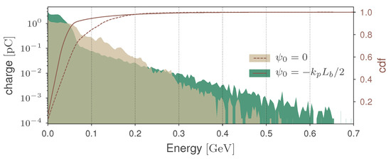
Figure 7.
Energy spectra and charge cdf for at , and at . At these propagation distances, both simulations attained their minimum total beam-energies, for and for .
Table 2.
Comparison between the energies at distinct values of the cumulative distribution functions, for both investigated phases.
4. Discussion and Conclusions
In this work, an active PBD was proposed to decelerate 1 GeV EuPRAXIA electron beams. PIC simulations were performed for two distinct initial phases, and . The total beam-energy loss obtained from such simulations showed good agreement with analytical estimates. While for the minimum total beam-energy of was observed at , for the minimum energy attained was at . Indeed, while 90% of the beam particles have energies lower than 0.06 GeV for , this value is two times higher (0.12 GeV) for . However, the more effective total beam-energy extraction observed for comes at the expense of having a longer tail of high-energy particles. Despite the very low charge, this tail extends up to ∼0.65 GeV. This can be explained as follows. By choosing a negative initial phase, the distance from the beam head to the end of the simultaneously decelerating and focusing laser-wake phase, , is increased. This allows for a more effective energy extraction from the beam head, at the expense of leaving a higher residual energy at the beam tail, which is initially placed at an accelerating phase of the laser wakefield for this choice of initial phase. However, it might be possible to optimise the initial phase (for example, by choosing , where ), in order to achieve a total beam-energy within the range of , with a tail of high-energy particles shorter than that observed in Figure 7 for .
Similarly to the passive PBD [23], a 5 GeV EuPRAXIA beam can also be dumped via the active scheme. However, if compared to the 1 GeV active PBD, both the higher beam energy, and the lower plasma density—which is required for preventing the premature dephasing of the 5 GeV beam—will affect the plasma length required for fully decelerating the beam. Simulations are currently underway, and they require large computing resources as the laser will propagate for a longer distance, and the laser wavelength needs to be resolved in the simulation. On the other hand, we are also exploring the SMILEI PIC code [31], aiming to take advantage of the laser envelope model implemented in this code. These results will be reported in a future work.
The laser and plasma parameters adopted in this work were chosen to ensure a homogeneous beam-energy extraction, along a propagation distance for which the beam dephasing is shorter than a quarter of the plasma wavelength (i.e., the length of the simultaneously decelerating and focusing phase of the laser wakefield). As it is mentioned later in this section, the active PBD laser energy is just a fraction of the laser energy adopted in the 1 GeV EuPRAXIA LWFA acceleration module. However, there might be room for further reduction, by adopting slightly lower values of plasma density and normalised laser strength parameter. However, such an optimization comes at the expense of increasing the plasma length and beam propagation distance. This may increase the complexity of a practical implementation of the active PBD scheme.
Engineering aspects for implementing an active PBD are similar to those required for implementing an LWFA. Regarding the plasma heating, in addition to the laser energy depletion [2], approximately ∼30 mJ will be deposited into the plasma for decelerating a 1 GeV, 30 pC beam in the active PBD. Therefore, the cooling requirements (if any) should be similar to those used in an LWFA with equivalent laser and plasma parameters. Regarding radiation hazards, previous works [16,17] have shown that they are greatly reduced if a PBD, rather than a conventional beam dump, is adopted. However, in order to ensure radiation safety, failure-proof mechanisms must be developed and implemented for the active PBD, before reducing the conventional beam dump size. Failures in the laser system, plasma cell, and/or beam phase injection may lead to problems ranging from no deceleration to acceleration, including radial ejection of beam particles. Therefore, implementing failure-proof systems to ensure a safe operation is a major challenge for enabling this technology. Among the possible solutions, interlocking both the accelerator and the active PBD might be one approach to be developed. A secondary, passive PBD, which is less prone to failures than the active case, could be added as well, in order to ensure at least some level of beam-energy extraction. Of course, such a system would also require failure-proof mechanisms to ensure a safe operation.
Achieving the benefit of compactness by adopting an active PBD strongly relies on the properties of the available laser systems. Although such benefit might not be readily available, advances in laser technology keep pushing forward the laser power, while maintaining—or reducing—the laser-system size. On the other hand, the same cannot be said about conventional beam dumps. Since they rely on the stopping power of their materials, conventional beam dumps will keep scaling with the ever-increasing beam energies aimed by new accelerator designs. Therefore, depending on the available laser technology, and the energy of the beam to be decelerated, an active PBD could potentially be much more compact than a conventional beam dump. When mentioning the possibility of future compact, transportable LWFA-based applications, it is assumed that a compact laser setup will be available for such finality. Within this context, adding a laser pulse for active PBD should not be a problem. On the other hand, large-scale facilities such as the EuPRAXIA project, and the existing designs for future LWFA-based linear colliders, aim to achieve high-energy beams by serially coupling multiple LWFA stages. In this scenario, in which each stage will require a laser driver, adding one more laser pulse for the active PBD should not be an issue. For implementing an active PBD in a current LWFA facility, a laser (coming from a single system) could be splitted into two pulses, one for driving the accelerator section, the other for driving the deceleration section.
Regarding the laser requirements for the active PBD, they are quite mild if compared with the parameters used for the EuPRAXIA 1 GeV accelerator. Depending on the final beam energy, the EuPRAXIA will utilise three laser facilities [14], so-called LASER1 (Injector 150 MeV), LASER2 (Injector 1 GeV) and LASER3 (Accelerator 5 GeV). The LASER2, to be used for producing a 1 GeV, 30 pC beam, has parameters such as laser wavelength of 800 nm, energy of 15–30 J, pulse duration of 20–30 fs, and repetition rate of 20–100 Hz. Depending on sizes of the focused laser beam waist, the normalised laser strength varies from 1 to 3. For the active PBD, a Gaussian laser pulse is used, with laser wavelength of 800 nm and normalised laser strength . Moreover, the 3–4 J laser-pulse energy required for the proposed active PBD is much lower than that specified for an EuPRAXIA 1 GeV acceleration stage. This is due to the lower normalised laser strength , and higher plasma density, since the laser dimensions scale with the plasma wavenumber (, and ) in the active PBD.
In addition, PBDs can be tuned and controlled by varying parameters such as operating density, density profile, type of gas, propagation length, among others. Due to the aforementioned advantages, and to the possibility of energy recovery from the plasma electrons, the adoption of PBDs could be an important milestone towards safer and greener facilities.
The research on plasma beam dump is still in its very early stage, if compared to the plasma wakefield acceleration research. The main focus of this study is to optimize the scheme so as to achieve a homogeneous total beam-energy extraction. Concerning the practical implementation of an active PBD, the aforementioned issues must be investigated and properly addressed, in order to take full advantage of the aforementioned active PBD benefits.
Author Contributions
Conceptualization, A.B., R.P.N. and G.X.; methodology, A.B., R.P.N. and G.X.; software (including post-processing data), A.B., R.P.N., B.S.N., S.K. and L.L.; draft preparation, A.B., R.P.N. and G.X.; writing—review and editing, all; visualization, A.B., R.P.N. and G.X. All authors have read and agreed to the current version of the manuscript.
Funding
This research was funded by the Cockcroft Institute Core Grant, the STFC, and the CNPq (Chamada Universal 427273/2016-1).
Data Availability Statement
The data presented in this study are available from the corresponding authors upon request.
Acknowledgments
The authors acknowledge the access to the Bede HPC system, provided by the N8 Centre of Excellence in Computationally Intensive Research, and to the Santos Dumont supercomputer, provided by the Laboratório Nacional de Computação Científica (LNCC). In addition, the authors acknowledge the developers of FBPIC and OpenPMD for their contributions to the scientific community, as well as the support they provide to the users.
Conflicts of Interest
The authors declare no conflict of interest.
Abbreviations
The following abbreviations are used in this manuscript:
| cdf | cumulative distribution function |
| LWFA | laser wakefield acceleration (or accelerator) |
| PBD | plasma beam dump |
| PIC | particle-in-cell |
References
- Tajima, T.; Dawson, J.M. Laser electron accelerator. Phys. Rev. Lett. 1979, 43, 267–270. [Google Scholar] [CrossRef]
- Esarey, E.; Schroeder, C.B.; Leemans, W.P. Physics of laser-driven plasma-based electron accelerators. Rev. Mod. Phys. 2009, 81, 1229–1285. [Google Scholar] [CrossRef]
- Strickland, D.; Mourou, G. Compression of amplified chirped optical pulses. Opt. Commun. 1985, 56, 219–221. [Google Scholar] [CrossRef]
- Agrawal, G.; Olsson, N. Self-phase modulation and spectral broadening of optical pulses in semiconductor laser amplifiers. IEEE J. Quantum Electron. 1989, 25, 2297–2306. [Google Scholar] [CrossRef]
- Nisoli, M.; Silvestri, S.D.; Svelto, O.; Szipöcs, R.; Ferencz, K.; Spielmann, C.; Sartania, S.; Krausz, F. Compression of high-energy laser pulses below 5 fs. Opt. Lett. 1997, 22, 522–524. [Google Scholar] [CrossRef]
- Leemans, W.P.; Nagler, B.; Gonsalves, A.J.; Toth, C.; Nakamura, K.; Geddes, C.G.R.; Esarey, E.; Schroeder, C.B.; Hooker, S.M. GeV electron beams from a centimetre-scale accelerator. Nat. Phys. 2006, 2, 696–699. [Google Scholar] [CrossRef]
- Leemans, W.P.; Gonsalves, A.J.; Mao, H.S.; Nakamura, K.; Benedetti, C.; Schroeder, C.B.; Tóth, C.; Daniels, J.; Mittelberger, D.E.; Bulanov, S.S.; et al. Multi-GeV Electron Beams from Capillary-Discharge-Guided Subpetawatt Laser Pulses in the Self-Trapping Regime. Phys. Rev. Lett. 2014, 113, 245002. [Google Scholar] [CrossRef]
- Gonsalves, A.J.; Nakamura, K.; Daniels, J.; Benedetti, C.; Pieronek, C.; de Raadt, T.C.H.; Steinke, S.; Bin, J.H.; Bulanov, S.S.; van Tilborg, J.; et al. Petawatt Laser Guiding and Electron Beam Acceleration to 8 GeV in a Laser-Heated Capillary Discharge Waveguide. Phys. Rev. Lett. 2019, 122, 084801. [Google Scholar] [CrossRef]
- Rykovanov, S.G.; Geddes, C.G.R.; Vay, J.L.; Schroeder, C.B.; Esarey, E.; Leemans, W.P. Quasi-monoenergetic femtosecond photon sources from Thomson Scattering using laser plasma accelerators and plasma channels. J. Phys. B At. Mol. Opt. Phys. 2014, 47, 1–22. [Google Scholar] [CrossRef][Green Version]
- Geddes, C.G.; Rykovanov, S.; Matlis, N.H.; Steinke, S.; Vay, J.L.; Esarey, E.H.; Ludewigt, B.; Nakamura, K.; Quiter, B.J.; Schroeder, C.B.; et al. Compact quasi-monoenergetic photon sources from laser-plasma accelerators for nuclear detection and characterization. Nucl. Instrum. Methods Phys. Res. Sect. Beam Interact. Mater. Atoms 2015, 350, 116–121. [Google Scholar] [CrossRef]
- Steinke, S.; van Tilborg, J.; Benedetti, C.; Geddes, C.G.R.; Schroeder, C.B.; Daniels, J.; Swanson, K.K.; Gonsalves, A.J.; Nakamura, K.; Matlis, N.H.; et al. Multistage coupling of independent laser-plasma accelerators. Nature 2016, 530, 190–193. [Google Scholar] [CrossRef] [PubMed]
- Leemans, W.; Esarey, E. Laser-driven plasma-wave electron accelerators. Phys. Today 2009, 62, 44–49. [Google Scholar] [CrossRef]
- Schroeder, C.B.; Esarey, E.; Geddes, C.G.R.; Benedetti, C.; Leemans, W.P. Physics considerations for laser-plasma linear colliders. PRST Accel. Beams 2010, 13, 101301. [Google Scholar] [CrossRef]
- Assmann, R.W.; Weikum, M.K.; Akhter, T.; Alesini, D.; Alexandrova, A.S.; Anania, M.P.; Andreev, N.E.; Andriyash, I.; Artioli, M.; Aschikhin, A.; et al. EuPRAXIA Conceptual Design Report. Eur. Phys. J. Spec. Top. 2020, 229, 3675–4284. [Google Scholar] [CrossRef]
- Takei, H.; Takeda, Y. Conceptual design of beam dump for high power electron beam. In Proceedings of the XVIII International Linear Accelerator Conference, Geneva, Switzerland, 26–30 August 1996; pp. 387–389. [Google Scholar]
- Wu, H.C.; Tajima, T.; Habs, D.; Chao, A.W.; Meyer-ter Vehn, J. Collective deceleration: Toward a compact beam dump. PRST Accel. Beams 2010, 13, 101303. [Google Scholar] [CrossRef]
- Bonatto, A.; Schroeder, C.B.; Vay, J.L.; Geddes, C.G.R.; Benedetti, C.; Esarey, E.; Leemans, W.P. Passive and active plasma deceleration for the compact disposal of electron beams. Phys. Plasmas 2015, 22, 083106. [Google Scholar] [CrossRef]
- Tajima, T.; Chao, A. Beam Stopping and its Energy Recovery Using Plasma. Japan Patent 2007-314155, 5 December 2007. [Google Scholar]
- Cowley, J.; Thornton, C.; Arran, C.; Shalloo, R.J.; Corner, L.; Cheung, G.; Gregory, C.D.; Mangles, S.P.D.; Matlis, N.H.; Symes, D.R.; et al. Excitation and Control of Plasma Wakefields by Multiple Laser Pulses. Phys. Rev. Lett. 2017, 119, 044802. [Google Scholar] [CrossRef]
- Chou, S.; Xu, J.; Khrennikov, K.; Cardenas, D.E.; Wenz, J.; Heigoldt, M.; Hofmann, L.; Veisz, L.; Karsch, S. Collective Deceleration of Laser-Driven Electron Bunches. Phys. Rev. Lett. 2016, 117, 290–295. [Google Scholar] [CrossRef]
- Hanahoe, K.; Xia, G.; Islam, M.; Li, Y.; Mete-Apsimon, Ö.; Hidding, B.; Smith, J. Simulation study of a passive plasma beam dump using varying plasma density. Phys. Plasmas (1994-Present) 2017, 24, 023120. [Google Scholar] [CrossRef]
- Jakobsson, O.; Bonatto, A.; Li, Y.; Zhao, Y.; Nunes, R.P.; Williamson, B.; Xia, G.; Tajima, T. Tailored plasma-density profiles for enhanced energy extraction in passive plasma beam dumps. Plasma Phys. Control. Fusion 2019, 61, 124002. [Google Scholar] [CrossRef]
- Xia, G.; Bonatto, A.; Nunes, R.P.; Liang, L.; Jakobsson, O.; Zhao, Y.; Williamson, B.; Davut, C.; Wang, X. Plasma Beam Dumps for the EuPRAXIA Facility. Instruments 2020, 4, 10. [Google Scholar] [CrossRef]
- Benedetti, C.; Rossi, F.; Schroeder, C.B.; Esarey, E.; Leemans, W.P. Pulse evolution and plasma-wave phase velocity in channel-guided laser-plasma accelerators. PRE 2015, 92, 023109. [Google Scholar] [CrossRef] [PubMed]
- Bonatto, A.; Schroeder, C.B.; Vay, J.L.; Geddes, C.G.R.; Benedetti, C.; Esarey, E.; Leemans, W.P. Compact disposal of high-energy electron beams using passive or laser-driven plasma decelerating stage. In Proceedings of the 16th Advanced Accelerator Concepts Workshop, San Jose, CA, Canada, 13–18 July 2014. [Google Scholar]
- Bonatto, A.; Nunes, R.; Xia, G. Energy Loss of an Electron Beam with Gaussian Density Profile Propagating in a Passive Plasma Beam Dump. In Proceedings of the IPAC’19, Melbourne, Australia, 19–24 May 2019; pp. 3584–3586. [Google Scholar]
- Li, X.; Mosnier, A.; Nghiem, P.A.P. Design of a 5 GeV laser–plasma accelerating module in the quasi-linear regime. Nucl. Inst. Methods Phys. Res. A 2018, 909, 49–53. [Google Scholar] [CrossRef]
- Lehe, R.; Kirchen, M.; Andriyash, I.A.; Godfrey, B.B.; Vay, J.L. A spectral, quasi-cylindrical and dispersion-free Particle-In-Cell algorithm. Comput. Phys. Commun. 2016, 203, 66–82. [Google Scholar] [CrossRef]
- Godfrey, B.B. Numerical Cherenkov instabilities in electromagnetic particle codes. J. Comput. Phys. 1974, 15, 504–521. [Google Scholar] [CrossRef]
- Huebl, A.; Lehe, R.; Vay, J.L.; Grote, D.P.; Sbalzarini, I.F.; Kuschel, S.; Sagan, D.; Mayes, C.; Perez, F.; Koller, F.; et al. openPMD: A Meta Data Standard for Particle and Mesh Based Data. 2015, p. 591699. Available online: https://doi.org/10.5281/zenodo (accessed on 2 July 2021).
- Derouillat, J.; Beck, A.; Pérez, F.; Vinci, T.; Chiaramello, M.; Grassi, A.; Flé, M.; Bouchard, G.; Plotnikov, I.; Aunai, N.; et al. Smilei: A collaborative, open-source, multi-purpose particle-in-cell code for plasma simulation. Comput. Phys. Commun. 2018, 222, 351–373. [Google Scholar] [CrossRef]


Publisher’s Note: MDPI stays neutral with regard to jurisdictional claims in published maps and institutional affiliations. |
© 2021 by the authors. Licensee MDPI, Basel, Switzerland. This article is an open access article distributed under the terms and conditions of the Creative Commons Attribution (CC BY) license (https://creativecommons.org/licenses/by/4.0/).