1. Introduction
Contact ultrasound inspection is a common technique for industrial non-destructive evaluation (NDE). Example applications are monitoring the integrity of critical components and process parameters in electric power generation stations and petrochemical plants. It is often desirable for long-term installation of ultrasonic transducers in elevated temperature environments to allow continuous on-line monitoring. This eliminates the need for costly plant shutdowns in order to carry out NDE tests, and also enables earlier warning of serious problems.
High-temperature ultrasonic inspection has been established using noncontact methods, such as ultrasonic laser interferometry. A common restriction on this technology is that specimens being evaluated must have polished or otherwise smooth surfaces, however successful ultrasound detection of cracks at temperatures up to 1000 °C has been demonstrated with reasonable sensitivity in materials with rough surfaces [
1].
Contact inspection using a delay line buffer rod has also been established at temperatures up to 960 °C, although a delay line length of up to 1 m may be required [
2]. In installations where the transducer components are not able to withstand extreme temperatures, the buffer rod and transducer environment must be separated and otherwise cooled to prevent damage to the transducer.
Direct contact inspection techniques are typically limited to temperatures below approximately 500 °C, even with the restriction of short duty cycles; continuous direct contact inspection is restricted to even lower temperatures [
3,
4]. There are several reasons for such temperature restrictions, including structural changes in the transducer materials, the differential rates of thermal expansion of transducer components, and limitations of the joining technique used to link the transducer components together.
All piezoelectric materials experience a permanent degradation or loss of their piezoelectric properties at a critical temperature known as the Curie point. Above this temperature a phase change in the material results in the loss of piezoelectric properties, even if the temperature is later reduced [
5,
6]. Piezoelectric materials which are common in industrial ultrasound transducers, such as lead zirconate titanate (PZT), have a maximum Curie point of the order of 400 °C. (The exact value depends on the PZT formulation). The Curie point of lithium niobate (LiNbO
3), a promising alternative to PZT for high temperature applications, is approximately 1150 °C. Several studies have shown that LiNbO
3-based transducers could be both effective and stable at extreme temperatures for long-term installation [
4,
7,
8].
In this study, the objective is to evaluate the performance of several brazing techniques for linking together the components of ultrasonic transducers for long-term, direct-contact use in high-temperature environments. Brazing and metal joining techniques can provide both mechanical bonding and acoustic coupling of the transducer layers, both of which are essential for long-term transducer operation. One approach to brazing relies on pre-coating the lithium niobate surface with a preliminary metallic layer, and then brazing directly to this metallic layer [
4,
9]. The mechanical integrity of the metallized layer, however, varies depending on the material and process used. As such, this study aims to identify suitable and reliable brazing techniques for mechanically and acoustically bonding to bare, non-metallized lithium niobate piezoelectric elements.
2. Materials and Methods
The piezoelectric elements used in this study were commercially produced rhombohedral 36° Y-cut lithium niobate discs designed for quasi-longitudinal wave generation at a resonant frequency of 3 MHz. The manufacturer-provided Curie point is 1150 °C, and the melting temperature is 1253 °C [
10]. The surface of the LiNbO
3 was fine lapped and bare of any electrode material. Prior to brazing, the surfaces of all components, including the braze material, were cleaned with acetone and allowed to dry completely.
In order to assess the quality of the brazed bond to lithium niobate, both mechanical and ultrasound assessments are required. It was therefore necessary to bond the piezoelectric element to a neighboring transducer backing component. In addition, to reduce thermally induced interfacial stress on the piezoelectric crystal, it is ideal to select a backing material whose coefficient of thermal expansion (CTE) is similar to that of the crystal. Porous zirconia was selected to serve as a mechanical damper to broaden the transducer bandwidth [
7]. Zirconia is an oxide-containing ceramic material with several material characteristics in common with lithium niobate, including CTE, such that it is a suitable mate for brazing trials with LiNbO
3 [
11].
A suitable brazing material used to join lithium niobate to a ceramic backing component for use in a high temperature transducer must meet several criteria:
It is ideal for the braze material to be conductive in order to simplify the transducer assembly process and provide electrical contact points for signal transmission in the final device. Metallic brazes also offer some degree of ductility once solidified, reducing the interfacial stress between LiNbO
3 and any neighboring component [
1].
The braze material must be able to withstand high temperatures in an oxidative environment.
For the braze to flow properly, the two components being joined must be heated above the liquidus or melting point of the braze material. This brazing temperature must however be below the Curie point of LiNbO3 (~1150 °C).
Although significant when selecting a backing material, the effect of a mismatch in the brazing material CTE is not likely to be significant when using such a thin layer, provided that the braze material itself is sufficiently ductile to prevent its own destruction due to thermally induced interfacial stresses.
The acoustic properties of the braze layer may have an effect on the overall acoustic transmission of the transducer, however these effects are unlikely to be significant if the braze thickness (
t) is sufficiently less than a wavelength (
) at the designed transducer frequency (i.e.,
) [
12,
13]. The exception is the case where the coupling material is significantly attenuative, as has been previously noted with some conductive adhesives [
7]. When a compromise between the mechanical and acoustical properties of a brazing material is required, priority must be placed on the ability of the material to maintain stable adhesion, and thereby acoustic coupling, between transducer components throughout the service temperature range.
Active brazes are one of two material categories which are candidate for our application. These materials rely on a chemical reaction between the braze material and substrate, and a resultant material transfer between layers. When oxides are present, the reaction mechanism typically relies on a dopant element in the braze material that bonds directly to the oxide in the substrate [
14]. Refractory metals such as titanium and chromium are commonly included as doping elements in small percentages for active brazing [
14]. In order to prevent premature oxidation of the dopant element, active brazing must typically be carried out in an inert or oxygen-reduced atmosphere. Active braze materials comprised of silver–copper–titanium, tin–silver–titanium, and aluminum–chromium–magnesium have exhibited some success in joining ceramic components [
15].
Passive brazes are a second category of material which rely solely on the mechanical interlocking and adhesion of the braze material to the substrate surface. Silver and gold-based alloys are common passive braze materials as they most effectively wet oxide-containing ceramic components [
14]. It is typically considered “best practice” [
14] to process passive brazes in an inert environment, however recent studies have indicated that some passive materials exhibit superior performance in a so-called “reactive air” brazing (RAB) atmosphere where brazing is carried out in ordinary air [
16,
17]. This has been shown to be particularly effective when joining ceramic components. One example relies on the partial oxidation of copper in the braze material to improve wetting of the substrate component and has been applied successfully to both metallic and ceramic substrates [
17].
Based on published literature and discussion with braze manufacturers, two active and two passive braze materials were identified for evaluation and are included in
Table 1. All braze materials were acquired as foils in the commercially available 50 μm thickness (less than 1/10 of a wavelength for compression waves at 3 MHz for the two transducer components being joined together).
A disc of each braze foil was placed at the interface between a LiNbO
3 element and a porous zirconia cylinder. Dimensions of the relevant components are given in
Table 2.
The stack of components was secured during the brazing process by an Inconel fixture suitable for high temperature use, shown in
Figure 1. Alignment features on the fixture allow the layers of the transducer stack to expand and contract longitudinally during the brazing process, accommodating dimensional variations due to both thermal expansion and the flow of braze material, while maintaining a fixed interfacial pressure of 90 kPa. This pressure lies within the recommended brazing pressure of 50 to 150 kPa to achieve good wetting of ceramic components [
14].
The braze materials were evaluated based on their performance when processed both in a high vacuum and in a reactive air atmosphere. Vacuum brazing was carried out in a VAC AERO VAH1212 HV furnace at a vacuum of approximately 58 μPa. Purging and cooling processes were performed using nitrogen gas. The reactive brazing process was initiated at an approximate temperature and relative humidity of 20 °C and 40–50% respectively in a typical benchtop box furnace.
The temperature profiles adopted for all brazing trials in this study featured two dwell points at which the temperature was held constant. The generic form of the profile was developed through numerous experiments, as well as a review of relevant literature and industry best practices, and is shown in
Figure 2 [
14,
21]. The first dwell occurs between 30 and 50 °C below the solidus or melting temperature of the braze material and lasts approximately 30 min. This allows all components to reach similar temperatures before brazing takes place. Following this dwell, the temperature is increased to approximately 10 to 30 °C above the melting or liquidus point of the braze material. This dwell lasts approximately 60 min, during which the braze material flows and wets all neighboring components. Following the second dwell, the sample was allowed to cool at a controlled rate.
Slow heating and cooling rates are essential to preventing cracking of the lithium niobate element due to thermally induced stress. Preliminary evaluation of sectioned samples using a scanning electron microscope indicated that heating and cooling rates in excess of 4 °C/min rate could lead to cracks in the piezoelectric disc prior to brazing. A typical bond resulting from these reduced rates is shown in
Figure 3.
3. Results
Preliminary qualitative evaluation of the bonds was carried out mechanically on a minimum of three samples of each brazing assembly to identify braze systems which resulted in satisfactory mechanical adhesion of LiNbO3 to the porous zirconia cylinder. Mechanical evaluation included verification of adhesion through application of both shear and peeling forces, visual assessment of the integrity of the crystal, and confirmation of electrical continuity across the brazed surface. As this study was focused on evaluating the ability of the brazed transducer assembly to transmit ultrasound signal, quantitative assessment of the mechanical performance of the bond under shear or tensile loads was not investigated. It is important to note that, as the specimen will be under compression when in use, a measure of the shear or tensile load under which the brazed bond will fail is not an effective indication of poor braze performance.
For those braze systems with which mechanical bonding was achieved, the brazing process was repeated to assemble additional samples for further evaluation. These assemblies were then assessed for their acoustic performance as an indication of effective mechanical and acoustic coupling between the layers.
For room-temperature acoustic performance evaluation, each piezoelectric element was coupled to a low carbon steel block approximately 36 mm thick using conventional ultrasound gel. A coupling pressure of approximately 250 MPa was selected based on a study of coupling pressure versus SNR of a LiNbO
3 crystal brazed with AgCu to porous zirconia, and fasteners were used to apply this clamping pressure.
Figure 4 shows a transducer assembly, including both piezoelectric element and porous zirconia backing layer, coupled to the steel piece.
For all evaluations, the piezoelectric crystal was excited with a rectangular pulse of 300 V amplitude and duration of 0.14 μs. This caused the piezoelectric element to generate an ultrasonic pulse centered at 3 MHz that was directed into both the backing layer and the steel test piece. The ultrasound echo reflected by the opposing surface of the steel test piece was then received and captured using an Agilent InfiniiVision DSO-X 2022A oscilloscope, sampling at a frequency of 250 MHz with 64 averaged acquisitions per capture to reduce random noise. The quality of the signal was then assessed on the basis of bandwidth and signal-to-noise ratio of the primary echo amplitude as compared with extraneous echoes and peaks generated by spurious reflections within the transducer assembly.
Once qualified for room temperature conditions, a similar process was carried out to evaluate transducer stacks at elevated temperatures. The transducer stack was dry-coupled directly to the test fixture with a coupling pressure of approximately 250 MPa and placed in a furnace. Ultrasound performance was evaluated at elevated temperatures in increments of 100 °C. At each temperature increment, the system was allowed to equilibrate for 15 min to ensure all components had reached the target temperature. The piezoelectric element was then excited and the reflected ultrasound signal was captured and assessed as previously described.
Table 3 summarizes the preliminary mechanical and acoustical performance at room temperature of each of the seven tested brazing systems. Two of the systems, featuring TiBraze
® Al665 and 72Ag-28Cu foils, were successful in both mechanical adhesion and acoustical bonding to LiNbO
3. Full results with those two particular braze systems over a range of elevated temperatures are described in detail in the sections which follow.
3.1. Room Temperature Tests—TiBraze® Al-665
The aluminum-based Al-665 foil from TiBraze
® utilizes both chromium and magnesium as dopant elements to achieve an active braze. It was found to mechanically bond to LiNbO
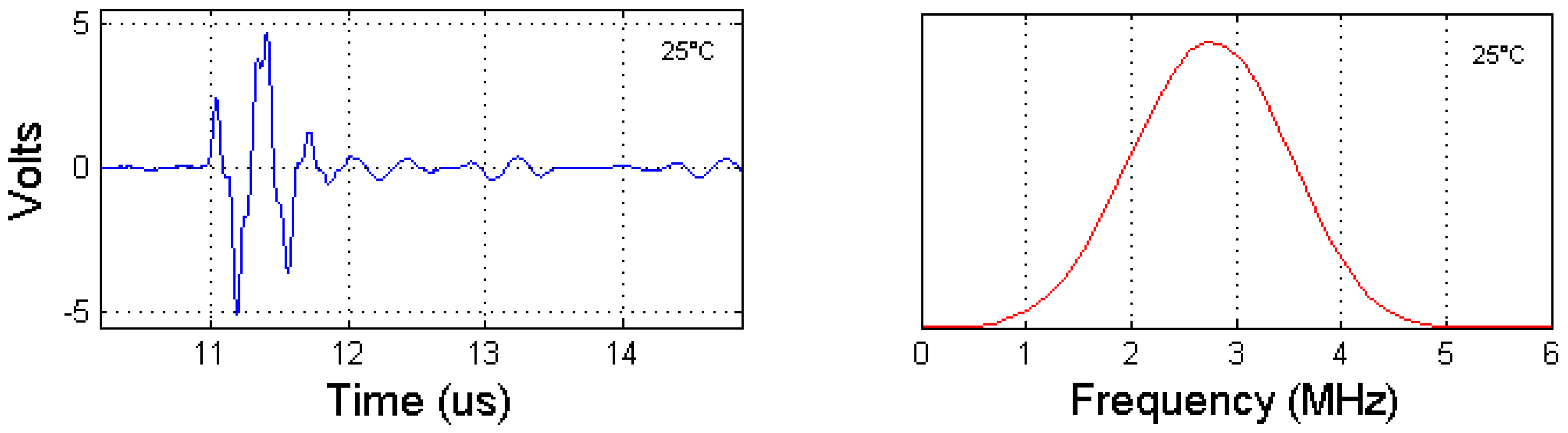
3 with highly repeatable results when processed in a high vacuum environment. Additionally, ultrasound echoes captured from the backwall of the steel test block at room temperature showed high amplitude; an example is shown in
Figure 5. The short echo pulse duration is a strong indicator that there is good acoustic coupling to the porous zirconia damping layer such that this layer can effectively perform its primary function of broadening the bandwidth of the system.
Samples were sectioned and inspected with a Hitachi TM3000 desktop scanning electron microscope in compositional backscattered detection mode with a 15-kV accelerating voltage. The SEM image of
Figure 6 shows that the braze material flowed into minor surface defects on the lithium niobate crystal, and the joint was free of gaps.
3.2. Room Temperature Tests—72Ag-28Cu Alloy
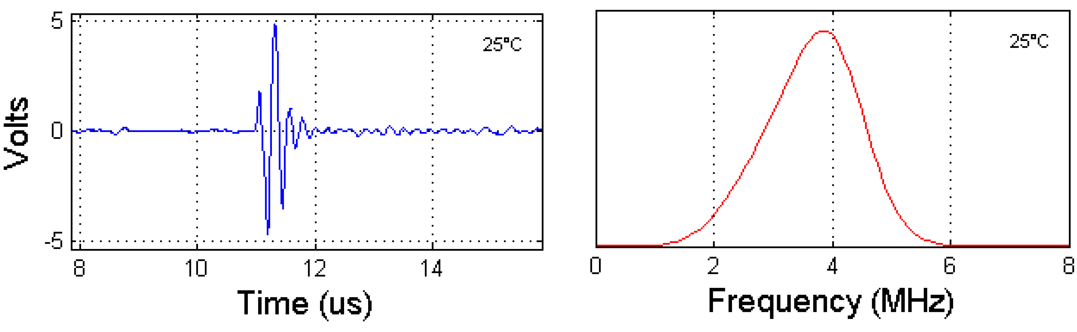
Repeatable mechanical and acoustic coupling was also achieved with the 72Ag-28Cu alloy, brazed in a reactive air environment. This braze material is comprised primarily of silver, often cited for its ability to wet oxide-containing ceramic materials, as well as copper, which tends to oxidize when heated under reactive air brazing conditions to yield good wetting. A typical ultrasound backwall echo from the steel test block at room temperature is shown in
Figure 7; it features high amplitude and a bandwidth of the order of 60%.
Significant oxidation was observed on the exposed surface areas of the brazing material not shielded by the piezoelectric crystal. This caused embrittlement of the foil, making it prone to fracture where not mechanically supported by neighboring joined components. Slight oxidation of the foil where sandwiched between transducer components was also observed through the translucent LiNbO3 crystal. Additionally, some minor crack patterns were noted visually on many LiNbO3 elements brazed using this method, however the cracks did not appear to lead to mechanical or electrical failure of the component, nor have a significant effect on the ultrasound performance of the assembled transducer stack.
3.3. Elevated Temperature Tests
As a primary motivation for identifying suitable bonding systems for lithium niobate is its high temperature performance, transducer stacks made with the two successful braze materials were also evaluated at elevated temperatures. The lithium niobate crystal in each assembly was dry coupled directly to the steel test fixture shown in
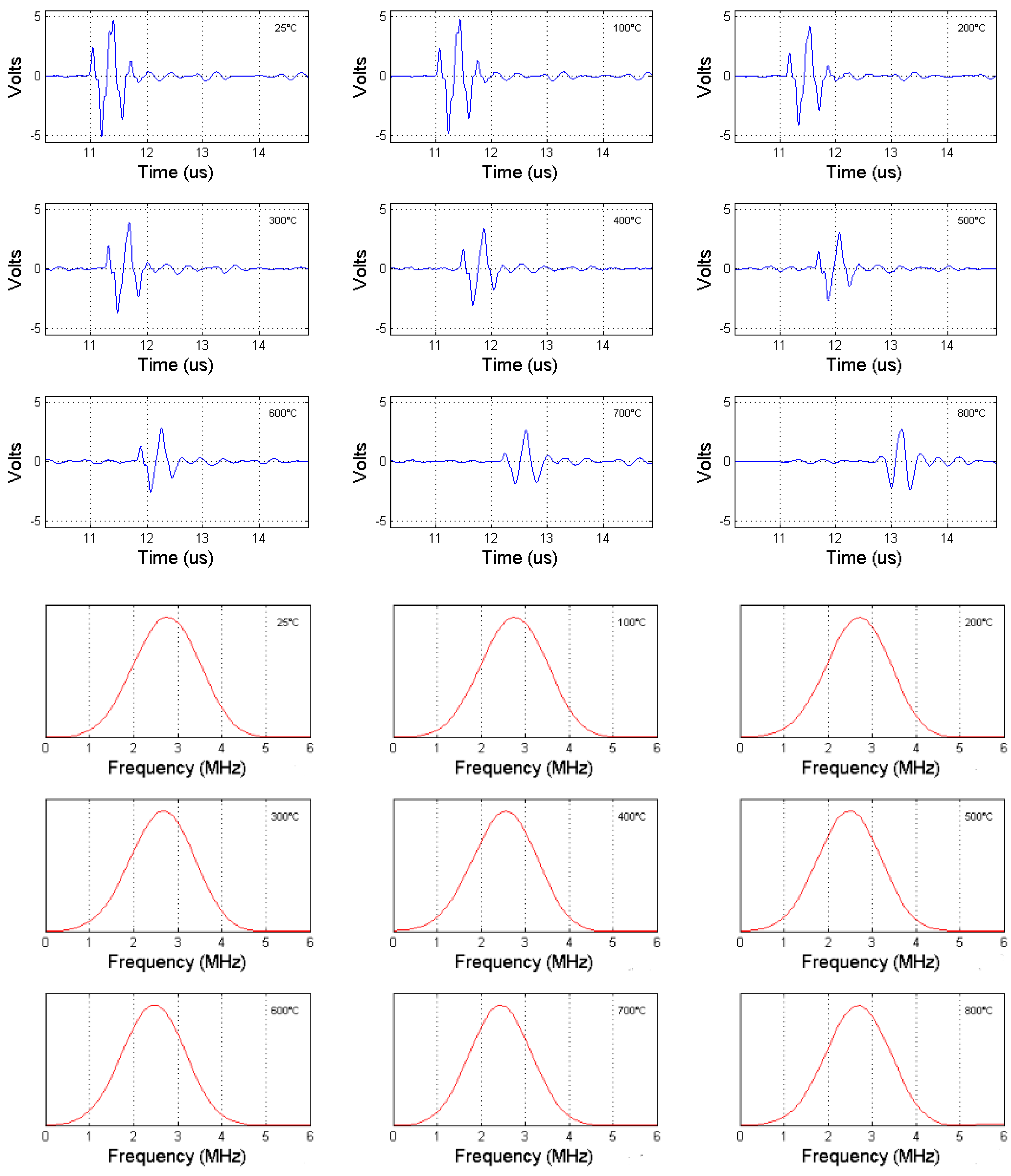
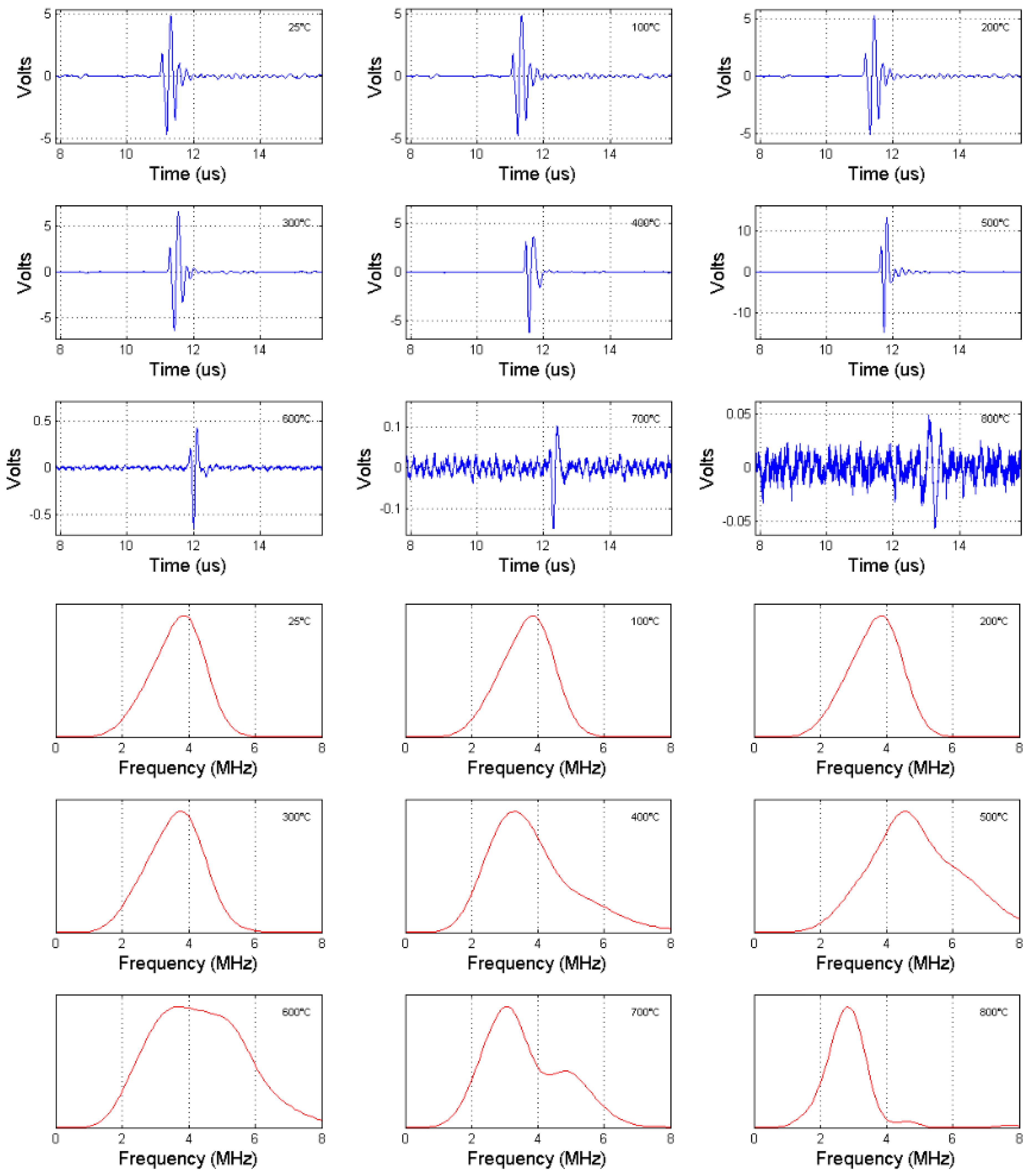
Figure 5 in a similar method to that previously described. The fixture was then heated in an oven with atmospheric air at a rate of 4 °C/min to a maximum temperature of 800 °C (approximately 400 °C below the lithium niobate Curie point) in stepped increments of 100 °C. An ultrasonic backwall echo was captured at each step in the heating program. The high-temperature performance of lithium niobate assemblies brazed with Al-665 and AgCu can be seen in the time and frequency domain backwall echo signals included in
Figure 8 and
Figure 9. It should be noted that an increase in the delay of arrival time of the backwall echoes is apparent with increasing temperature with both the Al-665 and AgCu-brazed samples. It is hypothesized that this is due both to the thermal expansion of the test-piece, as well as the decrease in ultrasound velocity in steel with increasing temperature [
22].
For the samples brazed with Al-665 foil, reception of ultrasonic backwall echoes with a signal-to-noise ratio in the range of 20–25 dB and a frequency spectrum centered near 4 MHz were realized at temperatures up to approximately 400 °C. As the system was heated further to temperatures approaching 500 °C, the amplitude of the backwall echo from the steel test block increased substantially up to a factor of three compared to its value at room temperature. Above 500 °C, rapid reduction of signal amplitude occurred, however a backwall echo could still be distinguished at temperatures up to 800 °C. At temperatures above 500 °C, typical signal-to-noise ratio of the system decreased drastically to as low as 5 dB at a test temperature of 800 °C due to a substantial decrease in echo amplitude and an increase in thermal noise in the system.
This variation with temperature in both the amplitude and resonant frequency of the Al-665-bonded transducer stack was accompanied with a wide range of bandwidth performance. At room temperature, the system bandwidth was 40–50% (~2 MHz), but varied in a range of 30% to 100% as the temperature was raised to 800 °C.
It is hypothesized that this temperature dependency is related to the mechanical properties of Al-665. Heating the transducer assembly above the annealing temperature of the aluminum-based foil (approximately 345 °C) may relax interfacial stresses between components generated during the brazing process. In addition, this softening may allow the braze material to more effectively acoustically couple the piezoelectric crystal to the backing material.
Temperatures exceeding 600 °C cause the Al-665 foil to melt. In such a state, the liquid material may be forced from the interface between the crystal and backing, resulting in a reduction of coupling pressure and an alteration in the boundary conditions at the interface. This may be accompanied by a reduction in signal amplitude as well as a change in the resonant conditions of the complete assembly, which may be manifested in a competing secondary resonance mode around 5 MHz apparent in transducer signals above 500 °C.
It is also possible that the temperature-dependency of signal attenuation is related to mechanical distortion of the transducer components, particularly the lithium niobate crystal, at elevated temperatures. The mechanical distortion may be caused by anisotropic properties of the lithium niobate crystal. A slight curvature or deviation in the flatness of the piezoelectric component may cause delamination and develop gaps in the brazed interface. This reversible distortion could account for some of the attenuation which is noted at temperatures above 600 °C. Further investigation of this behavior is warranted, possibly through finite element modeling.
These temperature-dependent effects on interfacial transmission must account for the observed variations in the ultrasound signal, as temperature-dependent changes in the piezoelectric efficiency of lithium niobate or the attenuation properties of the braze material would be unlikely to have such a significant effect.
Lithium niobate assemblies brazed with AgCu material typically exhibited less temperature-dependence of their properties than those brazed with Al-665. A consistent signal-to-noise ratio of approximately 20 dB was achieved with AgCu at temperatures up to 800 °C, despite a lower peak-to-peak signal amplitude of approximately 25% as compared with that of units brazed with Al-665. Analysis in the frequency domain indicated an expected center frequency near that of the lithium niobate element, centered between 2.5 and 3 MHz at all temperatures which were evaluated. An approximately 2 MHz, or 70%, half-power signal bandwidth remained consistent throughout the temperature range.
4. Discussion
Two brazing materials suitable for mechanical and acoustical coupling of bare lithium niobate piezoelectric elements in high temperature ultrasonic transducers were identified. These were: an aluminum-based foil, TiBraze® Al-665, for brazing in a high vacuum environment, and a silver–copper 72-28 alloy, suitable for brazing in reactive air. Several alternative joining systems were evaluated and eliminated on the basis of poor mechanical bonding or an inability to transmit ultrasound signals across interfaces inside the transducer.
Acoustic coupling was assessed through analysis of ultrasound backwall echoes generated by the piezoelectric element in a pulse-echo configuration while mounted to a steel test block. Two brazed transducer systems assembled with Al-665 and AgCu brazing foils transmitted and received ultrasound signals at temperatures up to 800 °C.
Transducers assembled using and a silver–copper 72-28 foil typically generated lower amplitude responses than those assembled with the Al-665 alloy; however, the echoes generated with the 72-28 alloy were easily distinguishable with a 20–25 dB signal-to-noise ratio at temperatures up to 800 °C. In addition, the variations in ultrasonic transmission efficiency exhibited at elevated temperatures by transducers brazed with Al-665 were not apparent with those brazed with AgCu. Instead, a consistent signal-to-noise ratio of approximately 20 dB was achieved with AgCu braze, and no appreciable reduction in signal amplitude or quality occurred over the 20 °C to 800 °C temperature range of interest.
The performance of transducers brazed with TiBraze® Al-665 foil was highly temperature dependent; signal-to-noise ratio fell substantially as the maximum temperature (800 °C) was approached. Both echo amplitude and resonant frequency were extremely variable at elevated temperatures. The use of the Al-665 to achieve repeatable and reliable mechanical and acoustical bonds to lithium niobate requires the use of a high vacuum brazing environment which could preclude the use of some materials as transducer components.
Given the potential for good signal-to-noise ratio and signal amplitude exhibited by the Al-665 foil at more moderate temperatures, future study surrounding the causes of its unexpected frequency and amplitude fluctuation at elevated temperatures is warranted. This may encompass an investigation into the melting characteristics of the chemically bonded brazing material, as well as the microscopic structure of the bonds linking it to LiNbO3 at various temperatures. The use of finite element modeling is recommended to identify whether anisotropic material properties, such as thermal expansion, may lead to mechanical distortion and corresponding attenuation of specimen.
In addition, further testing is required with both types of brazing foils to quantify the consistency of ultrasound transmission and mechanical adhesion achievable. A quantitative approach to characterization of the mechanical performance and failure limits for each material is advised.


