Article

High Efficiency Cyclotron Trap Assisted Positron Moderator

1
Institute for Particle Physics, ETH Zurich, Otto-Stern Weg 5, CH-8093 Zurich, Switzerland
2
Albert Einstein Center for Fundamental Physics (AEC), Laboratory for High Energy Physics (LHEP), University of Bern, Sidlerstrasse 5, CH-3012 Bern, Switzerland
3
Paul Scherrer Institute, CH-5232 Villigen, Switzerland
4
Institut Laue Langevin, 6 rue Jules Horowitz, F-38042 Grenoble CEDEX 9, France
5
Los Alamos National Laboratory, Los Alamos, NM 87545, USA
*
Author to whom correspondence should be addressed.
Instruments 2018, 2(3), 10; https://doi.org/10.3390/instruments2030010
Submission received: 16 May 2018 / Revised: 31 May 2018 / Accepted: 25 June 2018 / Published: 28 June 2018

Abstract

:
We report on the realisation of a cyclotron trap assisted positron tungsten moderator for the conversion of positrons with a broad keV–few MeV energy spectrum to a mono-energetic eV beam with an efficiency of 1.8(2)% defined as the ratio of the slow positrons divided by the β + activity of the radioactive source. This is an improvement of almost two orders of magnitude compared to the state of the art of tungsten moderators. The simulation validated with this measurement suggests that, using an optimised setup, even higher efficiencies are achievable. A novel method for the production of 48 V high-activity thin foil positron sources based on a solid target station at a medical cyclotron was developed. This is an improvement of more than one order of magnitude with respect to standard methods.

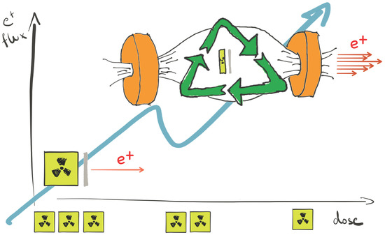
Graphical Abstract

1. Introduction

The positron and its bound state with an electron, positronium, have found many applications in physics and chemistry [1,2]. In medicine, they are used for what is probably the best known application of anti-matter in “everyday" life, the method of positron emission tomography (PET) [3]. Relying on their unique sensitivity to the electronic environment, positrons serve in applied science for the characterisation of materials. For example they provide one of the most sensitive techniques to detect defect concentrations [4]; they can be used to perform measurements of Fermi surfaces [5,6]; and they can bused to determine pore sizes in polymers [7] and nanoporous films [8]. The number of applications is continuously increasing, e.g., prompted by the growing complexity of advanced functional materials with multi-level porosity such as hierarchical zeolites and metal–organic frameworks [9,10]. Studies of positron and positronium interactions with matter are also a vibrant field of research [11,12].
As systems made of two elementary particles with no sub-structure, positronium (Ps), including Ps-ions and Ps 2 molecules, are ideal for testing bound state QED [13,14,15,16,17,18], fundamental symmetries [19,20] and to search for new physics [21]. Work is in progress to improve on the current results, to measure the effect of gravity on antimatter using Rydberg Ps [22] and to form a Ps Bose–Einstein condensate [23]. Positrons and positronium are also essential ingredients for the production of anti-hydrogen currently being studied at CERN [24,25,26,27,28].
The development of slow positron beams in the 1970s greatly expanded the possibilities of this field [29]. More recently, an additional boost was given by the advent of buffer gas traps allowing for manipulation and storage of large positron plasmas [30].
There are different ways to produce positrons which include the use of accelerators [31,32,33], nuclear reactors [34,35,36] or ultra-intense short pulsed lasers [37]. The most common and compact solution is to use radioactive isotopes that are β + emitters such as 22 Na [30]. To form a slow positron beam, the positrons from the broad keV to few MeV energy spectrum of the source have to be converted to a mono-energetic eV beam using moderators. Those can be divided into two classes: metals with a negative work function [38] and materials with very long diffusion lengths for positrons [39]. The best work function based moderators are thin single crystalline tungsten foils or tungsten meshes with efficiencies of the order of 10 4 [40]. The most efficient moderators rely on the long diffusion length of positrons in frozen rare gases, e.g., neon has a typical efficiency of ϵ = 7 × 10 3 [30].
In this paper, we present a scheme based on cyclotron trap assisted moderation that improves the amount of positrons available for the moderation process resulting in a higher efficiency.

2. Principle of the Cyclotron Trap Assisted Moderation

A cyclotron trap (CT) is a magnetic bottle consisting of two coaxially identical coils separated by a given distance (see Figure 1). By running a current in the same direction through the coils, the created magnetic field along their central axis has a maximum value B max at the center of each coil and a local minimum B min between them. This leads to the confinement of charged particles if their momenta perpendicular p and parallel p to the coil axis satisfy the relation (assuming adiabatic invariance):
p 0 p 0 B max B min 1 .
These particles then travel back and forth between the two coils on spiral trajectories along the trap axis.
In 1960, Gibson et al. [41] reported the confinement of positrons in a “mirror machine”. In the 1980s [42,43], Simons proposed a CT with a thin foil placed in its middle to be used as an energy degrader for slowing down anti-protons and negative muons [44] to keV energies. This scheme has been used in the recent measurement of the proton charge radius with muonic-hydrogen [45]. Waeber et al. [46] tried to implement the same approach for degrading positrons to energies of a few keV before their extraction and subsequent moderation outside the CT to form a mono-energetic beam. However, due to their very challenging extraction scheme, they could not reach the very promising theoretical predictions and this project was discontinued [47,48,49].
In the setup presented here, all the involved steps, i.e., the positron emission, the energy degradation, the moderation and the extraction are performed inside the cyclotron trap. The source, an activated 1 μ m thick titanium foil, and the moderator, a 1 μ m thick single crystal tungsten (110) foil, are matched and placed in the center of the cyclotron trap. This allows greatly increasing the amount of positrons available for moderation. The trapped positrons lose energy each time they pass through the foils. Once they have been degraded to energies of a few keV, they thermalise in the foils and can be re-emitted as slow positrons. The very narrow energy spread, due to the negative work function of tungsten, guarantees that slow positrons can be extracted with an efficiency close to 100% from the trap (see Equation (1)) when applying a small electric field.

3. Thin Foil Positon Source

The positron sources used in this experiment consisted of 1 μ m thick titanium foils containing the positron emitter 48 V produced via the reaction 48 Ti(p,n) 48 V. The activity and the thickness of the source are key parameters to obtain a positron beam with high intensity and an efficient extraction from the foil. The sources were produced by bombarding the titanium foils with 8 MeV protons at the ETHZ TANDEM accelerator and with 12 MeV protons using the external Beam Transfer Line (BTL) of the IBA 18 MeV medical cyclotron located at the Bern University Hospital (Inselspital) [50]. The source produced with the tandem had an activity of 20 kBq at EoB and was used for the first tests. Higher activities were produced with the cyclotron, where protons were moderated down to 12 MeV using carbon degraders before hitting the foils located along the BTL. Due to the very limited heat dissipation in vacuum, the beam current was set to a maximum of ~1 μ A . With this method, sources of 400 kBq in a surface of about 0.5 cm 2 were obtained with focused beams and irradiation times of about 16 h.
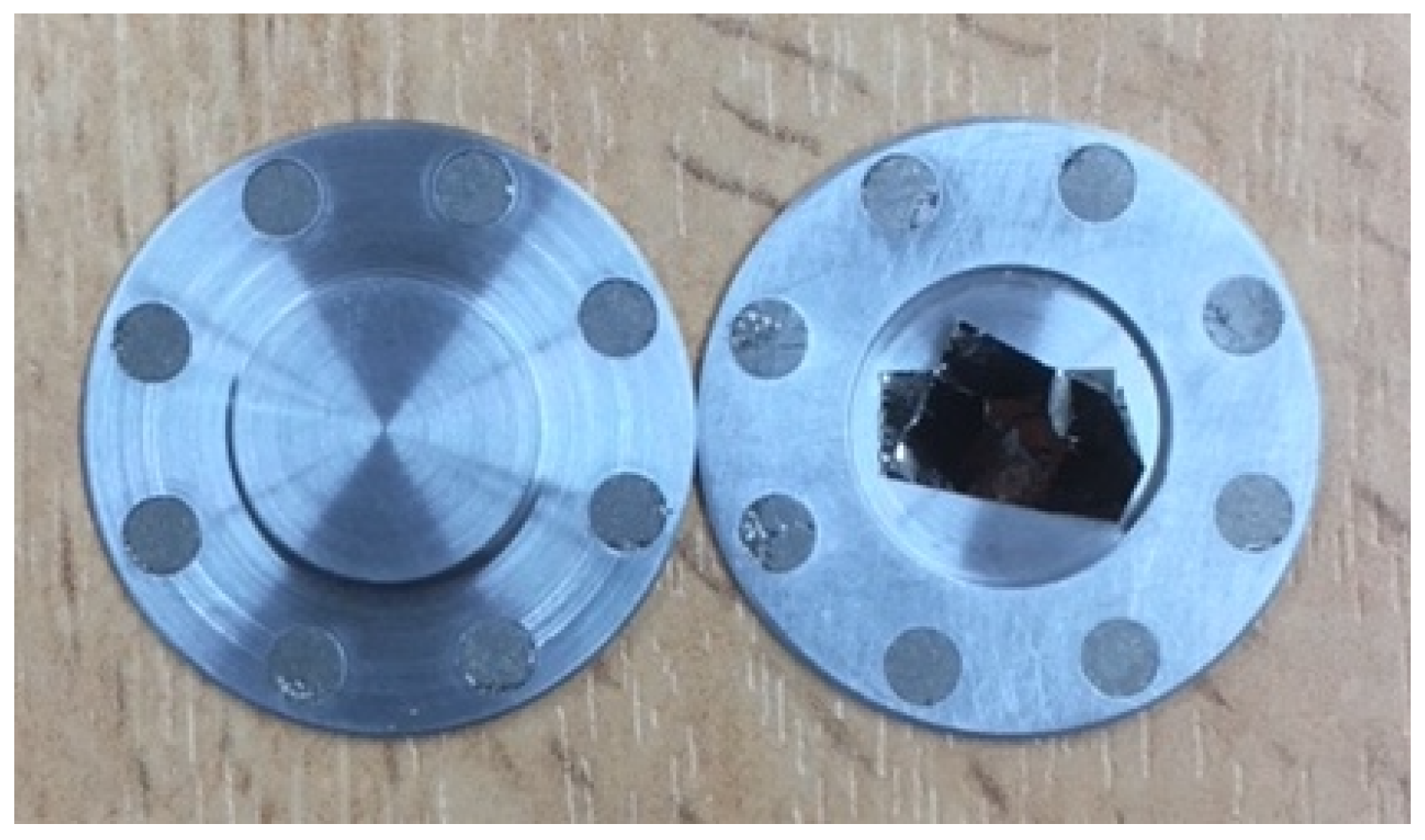
As shown in Table 1, 48 V offers some advantages with respect to the more usual 22 Na since it can be produced with low energy accelerators and its half-life of about 16 days eliminates radiation protection waste issues and allows the foil to be irradiated again and reused. The main problem is the modest activities that can be obtained with the standard methods described above. To obtain much high activities, cooling of the thin foil during bombardment is mandatory. For this reason, we conceived a specific technique based on the ongoing developments on the production of radioisotopes with the solid target station in operation at the Bern medical cyclotron. As shown in Figure 2, a specific coin target to host the titanium foil was developed. It consists of two aluminum halves kept together by eight couples of permanent magnets. The titanium foil is closed inside the two parts of the coin assuring an optimal thermal contact. When bombarded with the solid target station, the rear and the front halves are cooled by water and helium, respectively. The front part is traversed by the proton beam that is moderated down to 12 MeV, where the cross-section has a maximum value. With this method, currents of 20 μ A or more are easily achievable on a surface of ~1 cm 2 . A feasibility test with a 1 μ m 600 μ g foil irradiated for half an hour with a surface density current of 17 μ A/cm 2 was performed. An activity of 400 kBq at EoB was measured by gamma spectroscopy. These results are in good agreement with the calculations based on the cross sections. This represents an improvement of a factor 32 with respect to the standard method with the BTL and opens the way to the production of 10 MBq sources with irradiation of the order of 10 h using the nowadays wide-spread medical cyclotrons. Further developments are on-going aimed at focusing the beam down to ~2 mm FWHM on the solid target to obtain quasi point-like sources of higher activity [51]. Materials other than aluminum are also investigated to allow for higher currents and lower residual activation of the coin.
Alternative choices for the β + emitter are 58 Co and 22 Na with half-lives of 70 days and 2.6 years, respectively. Preliminary attempts to produce 58 Co via irradiation of 58 Ni foils were performed at the SINQ spallation source of the Paul Scherrer Institute (PSI) but only a very limited activity of few kBq was achieved. This reaction is suppressed for thermal neutrons and, ideally, one should use a fast reactor since the cross section for 58 Ni(n,p) becomes appreciable only for neutrons above 0.5 MeV. Moreover, 58 Co has a high capture cross-section for thermal neutrons, thus in this case the produced positron emitting isotope is depleted. The production of a 22 Na source has a higher threshold (see Table 1) and, to achieve comparable activities, it requires about 1000 times more protons on target than the 48 V production. The production of up to 20 MBq 22 Na sources by irradiation of 125 μ m aluminum foils with 72 MeV protons has been demonstrated in the past at PSI [52,53]. With commercial 70 MeV cyclotrons for isotope production [54], 1 MBq sources on 1 μ m foils could be produced in 10 days of irradiation with 80 μ A currents.
Remarkable features common to all thin metallic foil sources are their vacuum compatibility and the fact that the radioactive isotopes are well bound in the structure of the metal, an important issue for radiation safety.

4. Experimental Setup

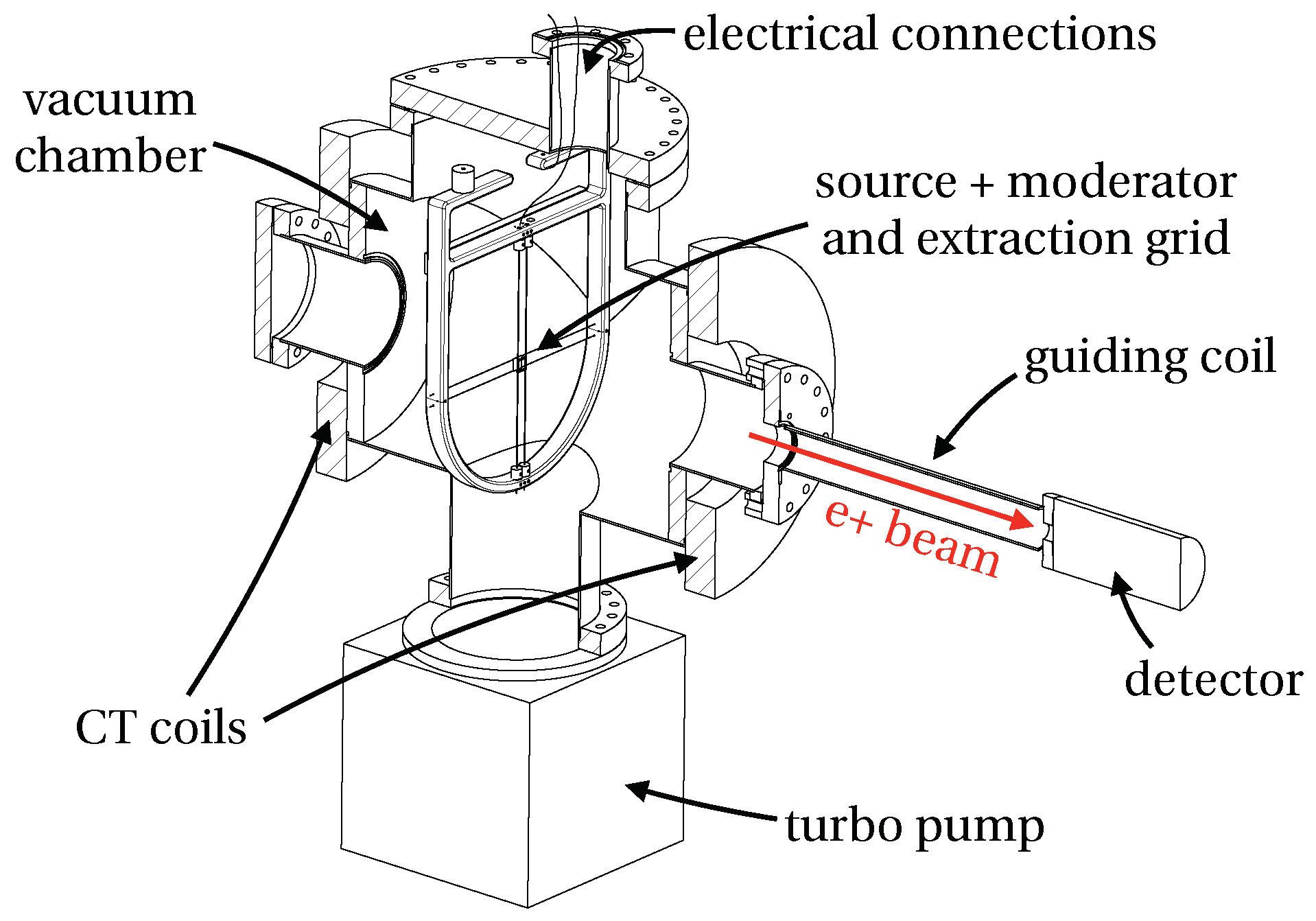
The experimental setup is schematically illustrated in Figure 3. The 1 μ m tungsten moderator was purchased from the Dept. of Physics and Astronomy of the University of Aarhus, Denmark and annealed 2 × 15 min through electron bombardment shortly before mounting it in the setup. For the slow positron extraction, a 96% transmission tungsten mesh was used. The cyclotron trap is formed by two identical water cooled coils that were re-used from an experiment at PSI [56] after removal of the iron yoke and refurbishing. The maximal characteristic values of the CT running with a current of 650 A are B max = 2.559 ( 2 ) kG and B min = 0.544 ( 2 ) kG corresponding to a magnetic field ratio of 4.704(17). The typical energy distribution of the moderator used in this experiment is Δ E , mod 1 eV [57,58,59]. Due to this energy spread, not all slow positrons can escape from the trap. To maximize the extraction efficiency, a grid has been added to produce a 200 V/cm electric field between moderator and grid.
To reduce the background from the annihilation in the source and from unmoderated positrons that could reach the detector, a 1 m long 100 G solenoid guides the positrons away from the CT (see Figure 3).
Due to the limited activity of the source available for this experiment, we selected an electron multiplier (EM) to detect the slow positrons since it has smaller dark counts (<1 count/s) compared to micro-channel plate detectors (MCPs). The drawback is that EMs are very sensitive to magnetic fields and therefore the positrons have to be extracted from the guiding field used for their transport. This was realized by terminating the magnetic field with Mu-metal shielding. Simulations with SIMION and COMSOL were used to optimise the extraction efficiency to values close to 100%. This was confirmed experimentally by using the ETHZ slow positron beam [52].

5. Simulation

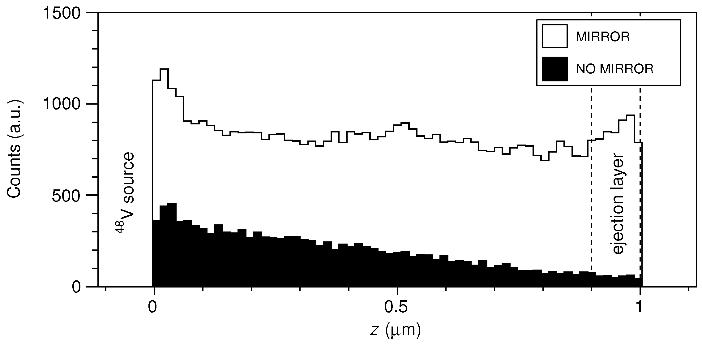
To design the cyclotron trap assisted positron moderator, we performed a detailed simulation with Geant 4 [60]. The CT magnetic field maps were created with COMSOL and Matlab. Geant 4 was validated to reproduce the correct positron stopping profiles [61] but does not include positron diffusion and the physics of the moderation process. Therefore, the simulation does not predict the moderation efficiency. To estimate it, we count the fraction of positrons stopping near the surface, in the so-called ejection layer (≈100 nm). In fact, those are the ones that have a probability to diffuse to the surface and be emitted as moderated positrons due to their negative work function in tungsten [62].
The simulation suggests that the extraction efficiency by applying +100 V on the source/moderator, with the grid at ground potential, is close to the 94% transmission of the grid. The number of fast positrons contributing to the background is expected to be below 10 4 . The simulation of our proof of principle setup for which 2 Ti foils of 1 μ m thickness where used in order to increase the available positron activity, predicts moderation efficiency of the order of 1%.
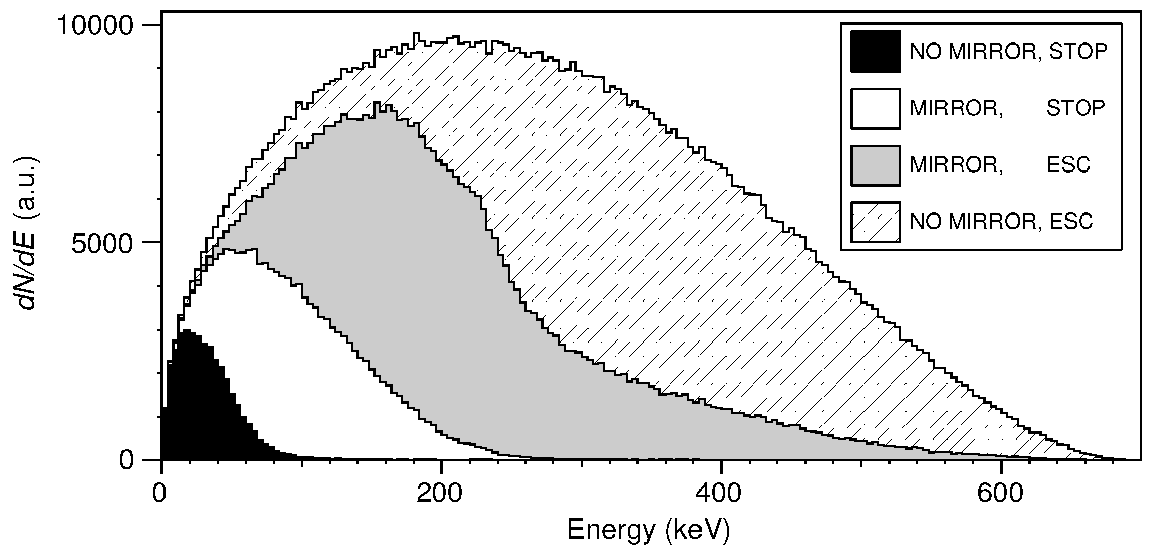
Figure 4 and Figure 5 illustrate the basic principle of assisted positron moderation with a CT. The overall advantage of the trap can be seen in Figure 4. Without a CT just the positrons in the low energy tail of the beta spectrum will stop inside the foil (black area in Figure 4). Of those, only the small fraction stopping in the ejection layer will actually get moderated. With the CT, trapped higher energetic positrons that did not stop in the first pass through the foil will have a chance to stop in one of the subsequent passages thus a part of the beta spectrum that is normally lost can be recycled (white area in Figure 4). The overall enhancement for stopping positrons is a factor of 5. The fact that the moderation efficiency actually improves by a much larger factor is illustrated in Figure 5. The contribution of mirrored positrons (white area), in the ejection layer on the moderator surface opposite to the source, is enhanced compared to the case where no CT is used (black area). This mimics the so-called reflection “geometry” which is known to have a higher slow positron yield [63].
The magnetic field of the CT used in this experiment is not strong enough to radially confine all the high energy positrons. The total amount of mirrored positrons are around 66% for a magnetic field ratio of about 5. As can be seen in Figure 4, only 30% of the them finally stop (white area) in the foils and the others escape (grey area). This is due to forward scattering at the foils. Simulations suggest that with a higher magnetic field ratio and a single source foil, even higher efficiencies are achievable with cyclotron trap assisted positron moderation.

6. Results

To measure the background due to the unmoderated positrons and photons reaching the detector, the source and the moderator are kept at ground potential while the extraction grid is biased to +100 V i to block the moderated positrons. In this configuration, 1 count/s was detected in the electron multiplier. In the extraction mode, +100 V are applied on the moderator while the grid is at ground, the number of counts in this case was 40 s 1 . The difference of counts between these two configurations, after correcting for the 70(3)% detection efficiency of the electron multiplier, is the number of moderated positrons. At the time of the experiment the positron activity was 3.2 ( 1 ) kBq, measured with a germanium detector and a calibration source. The division of the counts in the extraction mode by the total positron activity gives a moderation efficiency of of ϵ = 1.8 ( 2 ) % in fair agreement with what has been estimated from the simulation results.

7. Conclusions

The scheme presented here improves the positron moderation of state of the art tungsten moderators by almost two orders of magnitude. It can therefore produce the same output intensity from a much weaker radioactive source. It also yields a factor of two improvement compared to rare gas moderators but is operationally considerably simpler. The simulation validated with the measurement predicts that with this technique, using an optimised setup, higher efficiencies can be achieved. Therefore, this technique combined with a few MBq β + source on a 1 μ m foil would result in a positron flux of 10 4 positrons/s which is the typical value achieved with standard tungsten moderator based beams.
As a positron source, 48 V represents a valuable option if high activities can be provided. A novel method for the production of 48 V thin foil positron sources based on a solid target station at a medical cyclotron was developed and activities of the order of tens of MBq can be achieved. This is an improvement of more than one order of magnitude with respect to standard methods. Since the half-life of 48 V is about 16 days, the titanium foils can be stored until their radioactivity drops down to a negligible level and sent back to a cyclotron laboratory to be irradiated and reused.
This opens the possibility to envisage a widespread use of positron beams which are currently available only in few specialized laboratories around the world. Furthermore, this scheme could be used to increase the moderation efficiency and the yield at high intensity positron facilities, thus allowing for further advances in the positron and positronium field.

Acknowledgments

This work was supported by the Swiss National Science Foundation under Grant Numbers 200020_156756 and 200021_175749. We would like to thank the PSI, ETH Zurich IPP and AEC-LHEP workshops for their support.

Conflicts of Interest

The authors declare no conflict of interest.

References

  1. Charlton, M.; Humberston, J.W. Positron Physics; Cambridge University Press: Cambridge, UK, 2001; Volume 11. [Google Scholar]
  2. Jean, Y.C.; Mallon, P.E.; Schrader, D.M. Principles and Applications of Positron & Positronium Chemistry; World Scientific Publishing: Singapore, 2003. [Google Scholar] [CrossRef]
  3. Townsend, D.W. Physical principles and technology of clinical PET imaging. Ann. Acad. Med. Singap. 2004, 33, 133–145. [Google Scholar] [PubMed]
  4. Tuomisto, F.; Makkonen, I. Defect identification in semiconductors with positron annihilation: Experiment and theory. Rev. Mod. Phys. 2013, 85, 1583–1631. [Google Scholar] [CrossRef] [Green Version]
  5. Eijt, S.W.H.; van Veen, A.T.; Schut, H.; Mijnarends, P.E.; Denison, A.B.; Barbiellini, B.; Bansil, A. Study of colloidal quantum-dot surfaces using an innovative thin-film positron 2D-ACAR method. Nat. Mater. 2006, 5, 23–26. [Google Scholar] [CrossRef] [PubMed]
  6. Weber, J.A.; Bauer, A.; Böni, P.; Ceeh, H.; Dugdale, S.B.; Ernsting, D.; Kreuzpaintner, W.; Leitner, M.; Pfleiderer, C.; Hugenschmidt, C. Spin-Resolved Fermi Surface of the Localized Ferromagnetic Heusler Compound Cu2MnAl Measured with Spin-Polarized Positron Annihilation. Phys. Rev. Lett. 2015, 115, 206404. [Google Scholar] [CrossRef] [PubMed]
  7. Jean, Y.C.; Horn, J.D.V.; Hung, W.S.; Lee, K.R. Perspective of Positron Annihilation Spectroscopy in Polymers. Macromolecules 2013, 46, 7133–7145. [Google Scholar] [CrossRef]
  8. Gidley, D.W.; Peng, H.G.; Vallery, R.S. Positron annihilation as a method to characterize porous materials. Annu. Rev. Mater. Res. 2006, 36, 49–79. [Google Scholar] [CrossRef]
  9. Milina, M.; Mitchell, S.; Crivelli, P.; Cooke, D.; Pérez-Ramírez, J. Mesopore quality determines the lifetime of hierarchically structured zeolite catalysts. Nat. Commun. 2014, 5, 3922. [Google Scholar] [CrossRef] [Green Version]
  10. Crivelli, P.; Cooke, D.; Barbiellini, B.; Brown, B.L.; Feldblyum, J.I.; Guo, P.; Gidley, D.W.; Gerchow, L.; Matzger, A.J. Positronium emission spectra from self-assembled metal-organic frameworks. Phys. Rev. B 2014, 89, 241103. [Google Scholar] [CrossRef]
  11. Surko, C.M.; Gribakin, G.F.; Buckman, S.J. Low-energy positron interactions with atoms and molecules. J. Phys. B 2005, 38, R57. [Google Scholar] [CrossRef]
  12. Brawley, S.J.; Fayer, S.E.; Shipman, M.; Laricchia, G. Positronium Production and Scattering below Its Breakup Threshold. Phys. Rev. Lett. 2015, 115, 223201. [Google Scholar] [CrossRef] [PubMed]
  13. Karshenboim, S.G. Precision physics of simple atoms: QED tests, nuclear structure and fundamental constants. Phys. Rep. 2005, 422, 1–63. [Google Scholar] [CrossRef] [Green Version]
  14. Fee, M.S.; Mills, A.P.; Chu, S.; Shaw, E.D.; Danzmann, K.; Chichester, R.J.; Zuckerman, D.M. Measurement of the positronium 1(3)S(1)-2(3)S(1) interval by continuous-wave 2-photon excitation. Phys. Rev. Lett. 1993, 70, 1397–1400. [Google Scholar] [CrossRef] [PubMed]
  15. Ishida, A.; Namba, T.; Asai, S.; Kobayashi, T.; Saito, H.; Yoshida, M.; Tanaka, K.; Yamamoto, A. New Precision Measurement of Hyperfine Splitting of Positronium. Phys. Lett. 2014, B734, 338–344. [Google Scholar] [CrossRef] [Green Version]
  16. Fleischer, F.; Degreif, K.; Gwinner, G.; Lestinsky, M.; Liechtenstein, V.; Plenge, F.; Schwalm, D. Measurement of the decay rate of the negative ion of positronium (Ps(-)). Phys. Rev. Lett. 2006, 96. [Google Scholar] [CrossRef] [PubMed]
  17. Michishio, K.; Kanai, T.; Kuma, S.; Azuma, T.; Wada, K.; Mochizuki, I.; Hyodo, T.; Yagishita, A.; Nagashima, Y. Observation of a shape resonance of the positronium negative ion. Nat. Commun. 2016, 7. [Google Scholar] [CrossRef] [PubMed]
  18. Cassidy, D.B.; Hisakado, T.H.; Tom, H.W.K.; Mills, A.P., Jr. Optical Spectroscopy of Molecular Positronium. Phys. Rev. Lett. 2012, 108. [Google Scholar] [CrossRef] [PubMed] [Green Version]
  19. Vetter, P.A.; Freedman, S.J. Branching ratio measurements of multiphoton decays of positronium. Phys. Rev. A 2002, 66, 052505. [Google Scholar] [CrossRef]
  20. Yamazaki, T.; Namba, T.; Asai, S.; Kobayashi, T. Search for CP-violation in Positronium Decay. Phys. Rev. Lett. 2010, 104, 083401. [Google Scholar] [CrossRef] [PubMed]
  21. Badertscher, A.; Crivelli, P.; Fetscher, W.; Gendotti, U.; Gninenko, S.N.; Postoev, V.; Rubbia, A.; Samoylenko, V.; Sillou, D. An Improved Limit on Invisible Decays of Positronium. Phys. Rev. D 2007, 75, 032004. [Google Scholar] [CrossRef]
  22. Deller, A.; Alonso, A.M.; Cooper, B.S.; Hogan, S.D.; Cassidy, D.B. Electrostatically Guided Rydberg Positronium. Phys. Rev. Lett. 2016, 117. [Google Scholar] [CrossRef] [PubMed] [Green Version]
  23. Avetissian, H.K.; Avetissian, A.K.; Mkrtchian, G.F. Self-Amplified Gamma-Ray Laser on Positronium Atoms from a Bose-Einstein Condensate. Phys. Rev. Lett. 2014, 113. [Google Scholar] [CrossRef] [PubMed]
  24. Andresen, G.B.; Ashkezari, M.D.; Baquero-Ruiz, M.; Bertsche, W.; Bowe, P.D.; Butler, E.; Cesar, C.L.; Chapman, S.; Charlton, M.; Deller, A.; et al. Trapped antihydrogen. Nature 2010, 468, 673–676. [Google Scholar] [CrossRef] [PubMed]
  25. Gabrielse, G.; Kalra, R.; Kolthammer, W.S.; McConnell, R.; Richerme, P.; Grzonka, D.; Oelert, W.; Sefzick, T.; Zielinski, M.; Fitzakerley, D.W.; et al. Trapped Antihydrogen in Its Ground State. Phys. Rev. Lett. 2012, 108, 113002. [Google Scholar] [CrossRef] [PubMed]
  26. Kuroda, N.; Ulmer, S.; Murtagh, D.J.; Van Gorp, S.; Nagata, Y.; Diermaier, M.; Federmann, S.; Leali, M.; Malbrunot, C.; Mascagna, V.; et al. A source of antihydrogen for in-flight hyperfine spectroscopy. Nat. Commun. 2014, 5, 3089. [Google Scholar] [CrossRef] [PubMed] [Green Version]
  27. Testera, G.; Aghion, S.; Amsler, C.; Ariga, A.; Ariga, T.; Belov, A.; Bonomi, G.; Braunig, P.; Bremer, J.; Brusa, R.; et al. The AEgIS experiment. Hyperfine Interact. 2015, 233, 13–20. [Google Scholar] [CrossRef]
  28. Perez, P.; Banerjee, D.; Biraben, F.; Brook-Roberge, D.; Charlton, M.; Clade, P.; Comini, P.; Crivelli, P.; Dalkarov, O.; Debu, P.; et al. The GBAR antimatter gravity experiment. Hyperfine Interact. 2015, 233, 21–27. [Google Scholar] [CrossRef]
  29. Coleman, P.G. (Ed.) Positron Beams and Their Applications; World Scientific Publishing: Singapore, 2000. [Google Scholar] [CrossRef]
  30. Danielson, J.R.; Dubin, D.H.E.; Greaves, R.G.; Surko, C.M. Plasma and trap-based techniques for science with positrons. Rev. Mod. Phys. 2015, 87, 247–306. [Google Scholar] [CrossRef] [Green Version]
  31. Krause-Rehberg, R.; Brauer, G.; Jungmann, M.; Krille, A.; Rogov, A.; Noack, K. Progress of the intense positron beam project EPOS. Appl. Surf. Sci. 2008, 255, 22–24. [Google Scholar] [CrossRef] [Green Version]
  32. Oshima, N.; Suzuki, R.; Ohdaira, T.; Kinomura, A.; Narumi, T.; Uedono, A.; Fujinami, M. Development of Positron Microbeam in AIST. In Positron and Positronium Chemistry; Trans Tech Publications: Stafa-Zurich, Switzerland, 2009; Volume 607, pp. 238–242. [Google Scholar] [CrossRef]
  33. Patrice, P.; Laszlo, L.; Jean-Michel, R.; Valentin, B.; Mickael, C.; Aline, C.; Olivier, D.; Pierre, D.; Tomoko, M.; Nicolas, R.; et al. A mini linac based positron source. Phys. Status Solidi C 2009, 6, 2462–2464. [Google Scholar] [CrossRef]
  34. Schut, H.; van Veen, A.; Falub, C.; de Roode, J.; Labohm, F. Performance of an Intense Nuclear-Reactor Based Positron Beam. In Positron Annihilation—ICPA-12, Proceedings of the 12th International Conference on Positron Annihilation, Munchen, Germany, 6–12 August 2000; Trans Tech Publications: Stafa-Zurich, Switzerland, 2001; Volume 363, pp. 430–432. [Google Scholar] [CrossRef]
  35. Hawari, A.I.; Gidley, D.W.; Moxom, J.; Hathaway, A.G.; Mukherjee, S. Operation and testing of the PULSTAR reactor intense slow positron beam and PALS spectrometers. In Proceedings of the 12th International Workshop on Slow Positron Beam Techniques, (SLOPOS12), North Queensland, Australia, 1–6 August 2010; Buckman, S.J., Sullivan, J.P., Makochekanwa, C., White, R., Eds.; Institute of Physics Publishing: Bristol, UK, 2011; Volume 262. [Google Scholar] [CrossRef]
  36. Hugenschmidt, C.; Ceeh, H.; Gigl, T.; Lippert, F.; Piochacz, C.; Reiner, M.; Schreckenbach, K.; Vohburger, S.; Weber, J.; Zimnik, S. Positron Beam Characteristics at NEPOMUC Upgrade. In Proceedings of the 13th International Workshop on Slow Positron Beam Techniques and Applications (SLOPOS13), Munich, Germany, 15–20 September 2013; Hugenschmidt, C., Piochacz, C., Eds.; Institute of Physics Publishing: Bristol, UK, 2014; Volume 505. [Google Scholar] [CrossRef]
  37. Chen, H.; Wilks, S.C.; Bonlie, J.D.; Liang, E.P.; Myatt, J.; Price, D.F.; Meyerhofer, D.D.; Beiersdorfer, P. Relativistic Positron Creation Using Ultraintense Short Pulse Lasers. Phys. Rev. Lett. 2009, 102, 105001. [Google Scholar] [CrossRef] [PubMed]
  38. Lynn, K.G.; Nielsen, B.; Quateman, J.H. Development and use of a thin film transmission positron moderator. Appl. Phys. Lett. 1985, 47, 239–240. [Google Scholar] [CrossRef]
  39. Mills, A.P.; Gullikson, E.M. Solid neon moderator for producing slow positrons. Appl. Phys. Lett. 1986, 49, 1121–1123. [Google Scholar] [CrossRef]
  40. Saito, F.; Nagashima, Y.; Wei, L.; Itoh, Y.; Goto, A.; Hyodo, T. A high-efficiency positron moderator using electro-polished tungsten meshes. Appl. Surf. Sci. 2002, 194, 13–15. [Google Scholar] [CrossRef]
  41. Gibson, G.; Jordan, W.; Lauer, E. Containment of positrons in a mirror machine. Phys. Rev. Lett. 1960, 5, 141–144. [Google Scholar] [CrossRef]
  42. Simons, L.M. Recent results on anti-protonic atoms using a cyclotron trap at lear. Phys. Scr. 1988, T22, 90–95. [Google Scholar] [CrossRef]
  43. Eades, J.; Simons, L.M. Deceleration in an Anticyclotron as a Means of Producing very Low-energy Anti-protons. Nucl. Instrum. Meth. 1989, A278, 368–374. [Google Scholar] [CrossRef]
  44. Simons, L. The cyclotron trap for antiprotons. Hyperfine Interact. 1993, 81, 253–262. [Google Scholar] [CrossRef]
  45. Pohl, R.; Antognini, A.; Nez, F.; Amaro, F.D.; Biraben, F.; Cardoso, J.M.R.; Covita, D.S.; Dax, A.; Dhawan, S.; Fernandes, L.M.P.; et al. The size of the proton. Nature 2010, 466, 213–216. [Google Scholar] [CrossRef] [PubMed]
  46. Shi, M.; Waeber, W.; Gerola, D.; Zimmermann, U.; Taqqu, D. Premoderation of positrons—Experiments on positron trapping and slowing-down. Nucl. Inst. Methods Phys. Res. A 1994, 349, 8–14. [Google Scholar] [CrossRef]
  47. Gerola, D.; Waeber, W.; Shi, M.; Wang, S. Quasidivergency-free extraction of a slow positron beam from high magnetic fields. Rev. Sci. Instrum. 1995, 66, 3819–3825. [Google Scholar] [CrossRef]
  48. Gerola, D.; Waeber, W.; Shi, M. High efficiency positron moderation a feasibility study of the slow beam confinement extraction. Nucl. Inst. Methods Phys. Res. A 1995, 364, 33–43. [Google Scholar] [CrossRef]
  49. Waeber, W.B.; Shi, M. High performance hybrid slow positron beam and its user application spectrum. Appl. Surf. Sci. 1997, 116, 91–97. [Google Scholar] [CrossRef]
  50. Braccini, S. The New Bern PET Cyclotron, Its Research Beam Line, and the Development of an Innovative Beam Monitor Detector. In Application of Accelerators in Research and Industry, Proceedings of the 22nd International Conference on the Application of Accelerators in Research and Industry (CAARI), Fort Worth, TX, USA, 5–10 August 2012; McDaniel, F.D., Doyle, B.L., Glass, G.A., Wang, Y., Eds.; Sandia National Laboratories: Livermore, CA, USA, 2013; Volume 1525, pp. 144–150. [Google Scholar] [CrossRef]
  51. Braccini, S. Compact Medical Cyclotrons and their use for Radioisotope Production and Multi-disciplinary Research. In Proceedings of the International Conference on Cyclotrons and Their Applications, Cape Town, South Africa, 8–13 October 2016; JACoW: Geneva, Switzerland, 2017; pp. 229–234. [Google Scholar] [CrossRef]
  52. Alberola, N.; Anthonioz, T.; Badertscher, A.; Bas, C.; Belov, A.; Crivelli, P.; Gninenko, S.; Golubev, N.; Kirsanov, M.; Rubbia, A.; et al. Development of a high-efficiency pulsed slow positron beam for measurements with orthopositronium in vacuum. Nucl. Instr. Meth. Phys. Res. A 2006, 560, 224–232. [Google Scholar] [CrossRef] [Green Version]
  53. Gendotti, U. Design of an Experiment to Search for Invisible Decays of Ortho-Positronium in Vacuum and Ortho-Positronium Formation Studies in Mesostructured Silica Films. Ph.D. Thesis, ETH Zurich, Zürich, Switzerland, 2010. [Google Scholar] [CrossRef]
  54. Schmor, P.W. Review of cyclotrons used in the production of radioisotopes for biomedical applications. In Proceedings of the International Conference on Cyclotrons and Their Applications (Cyclotrons ’10), Lanzhou, China, 6–10 September 2010; pp. 419–424. [Google Scholar]
  55. International Atomic Energy Agency—Nuclear Data Section. Available online: https://www-nds.iaea.org (accessed on 4 February 2016).
  56. Danneberg, N.; Fetscher, W.; Kohler, K.; Lang, J.; Schweizer, T.; von Allmen, A.; Bodek, K.; Jarczyk, L.; Kistryn, S.; Smyrski, J.; et al. Muon decay: Measurement of the transverse polarization of the decay positrons and its implications for the Fermi coupling constant and time reversal invariance. Phys. Rev. Lett. 2005, 94, 021802. [Google Scholar] [CrossRef] [PubMed]
  57. Vehanen, A.; Lynn, K.; Schultz, P.; Eldrup, M. Improved slow-positron yield using a single crystal tungsten moderator. Appl. Phys. A 1983, 32, 163–167. [Google Scholar] [CrossRef]
  58. Pendyala, S.; Bartell, D.; Girouard, F.; Mcgowan, J. Energy-distribution of slow positrons diffusing from incomplete d-shell transition-metals. Phys. Rev. Lett. 1974, 33, 1031–1034. [Google Scholar] [CrossRef]
  59. Gramsch, E.; Throwe, J.; Lynn, K.G. Development of transmission positron moderators. Appl. Phys. Lett. 1987, 51, 1862–1864. [Google Scholar] [CrossRef]
  60. Agostinelli, S.; Allison, J.; Amako, K.; Apostolakis, J.; Araujo, H.; Arce, P.; Asai, M.; Axen, D.; Banerjee, S.; Barrand, G.; et al. GEANT4: A Simulation toolkit. Nucl. Instrum. Meth. 2003, A506, 250–303. [Google Scholar] [CrossRef]
  61. Dryzek, J.; Horodek, P. GEANT4 simulation of slow positron beam implantation profiles. Nucl. Instrum. Methods Phys. Res. B 2008, 266, 4000–4009. [Google Scholar] [CrossRef]
  62. Mills, A.P. Positron moderation and remoderation techniques for producing cold positron and positronium sources. Hyperfine Interact. 1989, 44, 105–123. [Google Scholar] [CrossRef]
  63. Williams, A.I.; Murtagh, D.J.; Fayer, S.E.; Andersen, S.L.; Chevallier, J.; Kövér, A.; Reeth, P.V.; Humberston, J.W.; Laricchia, G. Moderation and diffusion of positrons in tungsten meshes and foils. J. Appl. Phys. 2015, 118, 105302. [Google Scholar] [CrossRef] [Green Version]
Figure 1. Scheme of the cyclotron assisted moderator principle. Two thin Ti activated foils ( 48 V), indicated as “source”, and the W(110) foil, indicated as “moderator”, placed inside a cyclotron trap act as a positron emitter, energy degrader and moderator. The confined positrons emitted from the source (kept at +100 V) lose energy passing through the foils until they are moderated. The use of a grid at ground potential maximizes the efficiency of the extraction of the moderated positrons.
Instruments 02 00010 g001
Figure 2. The two halves of the “coin” target held together by eight couples of permanent magnets. The rear half (on the left) is water cooled and matches the front half (on the right) that is used to degrade the beam to the desired energy.
Instruments 02 00010 g002
Figure 3. Schematic of the setup consisting of the vacuum chamber, the two coils forming the magnetic bottle, the guiding coil, the source, the moderator, the extraction grid mount, and the detector.
Instruments 02 00010 g003
Figure 4. Simulated positron energy spectrum of 48 V separated into fraction of positrons which were not mirrored and stopped inside the moderator or source foil (black area), mirrored at least once and stopped (white area), mirrored at least once and escaped the trap (grey area) and not mirrored and escaped (hatched area).
Instruments 02 00010 g004
Figure 5. Simulated axial stopping position z split into mirrored (white area) and not mirrored (black area) events. The W moderator foil range from 0 to 1 μ m. The 48 V source sits on the z side of the moderator. The ejection layer ranging from 0.9 to 1 μ m is marked by the dashed lines.
Instruments 02 00010 g005
Table 1. Endpoint energy T max of the β + , half-life t 1 / 2 , β + branching Γ ( β + ) , production target and reaction, maximum cross-section σ max ( E σ ) [55], corresponding projectile energy E σ , EOB activity A EOB for 1 μ m foil sources of 58 Co, 22 Na and 48 V.
Isotope 58 Co 22 Na 48 V
T max [keV]475545695
t 1 / 2 [d]70.8595015.97
Γ ( β + ) [%]14.990.650
Reaction 58 Ni(n fast ,p) 27 Al(p,X) 48 Ti(p,n)
σ max ( E σ ) [mb]60044382
E σ [MeV]104412
ρ target [ g / cm 3 ]8.92.74.5
A EOB [kBq/10 16 neutrons]47.5--
A EOB [kBq/ μ Ah]-0.0524