Article

Experimental and Numerical Investigations on the Parameters of a Synchronous Machine Prototype with High-Temperature Superconductor Armature Windings

1
Research Group in Electric Energy of Nancy (GREEN), Université de Lorraine, GREEN, Campus des Aiguillettes, F-54000 Nancy, France
2
Ecole Militaire Polytechnique, UER ELT, Algiers 16111, Algeria
*
Author to whom correspondence should be addressed.
Condens. Matter 2023, 8(4), 94; https://doi.org/10.3390/condmat8040094
Submission received: 30 September 2023 / Revised: 31 October 2023 / Accepted: 7 November 2023 / Published: 9 November 2023

Abstract

:
In their applications in electrical machines, high-temperature superconductors (HTSs) are mainly used as inductors in synchronous machines due to the AC losses which can lead to high cryogenic costs. In this work, we show the possibility of their use as armature windings, handling some precautions. The approach is based on the combined use of modeling and measurements. The construction and the preliminary tests of a handmade prototype of an axial field HTS synchronous machine are presented. Several tests have been conducted at liquid nitrogen temperature. The measurements have been confirmed by modeling results. The preliminary tests on the prototype, in both modeling and measurements, are very promising.

1. Introduction

Superconducting machines are an important area of research related to applied superconductivity, in particular with the development of high-temperature superconductors (HTSs), presenting low cryogenic costs. For large power applications, the use of superconducting materials can provide high performances in terms of efficiency and power density. Indeed, such materials can withstand high current densities with very low losses.
The commonly encountered structures of HTS machines are similar to those of conventional ones. The majority of HTS AC machines produced are synchronous, in which the superconducting part is limited to the field coil [1,2,3]. A reduction in mass of up to 40% can be achieved for large power machines [4,5,6].
Original machine structures have been developed using HTSs in a massive form (bulk), as superconducting magnets replacing permanent magnets [7,8], or as superconducting screens to obtain a certain spatial modulation of the magnetic field [9,10].
Fully superconducting machines use superconducting materials in both the armature and the inductor windings. This type of machine has more advantages, such as increasing the current density of the armature, reducing the Joule losses and decreasing the thickness of the air gap (the cryostat enclosing the whole machine), which makes it possible to achieve higher power densities and efficiencies. However, AC losses are still a significant brake on their development, even though the feasibility and efficiency have been proven through various prototypes: totally superconducting [11,12], or hybrid including permanent magnets-type inductors and superconducting armatures [13,14,15,16]. Twisted filament high-temperature superconducting tapes and MgB2 wires seem to be potential candidates for such structures [17].
In this work, we present the implementation and the tests of a prototype of an axial flux synchronous machine with a superconducting armature. An integral modeling approach has been developed to determine the critical current of the coils and the global quantities characterizing the machine. We describe the different measurements carried on the prototype and provide some results, obtained through both modeling and measurements, that are complementary to those presented in a previous work [18].

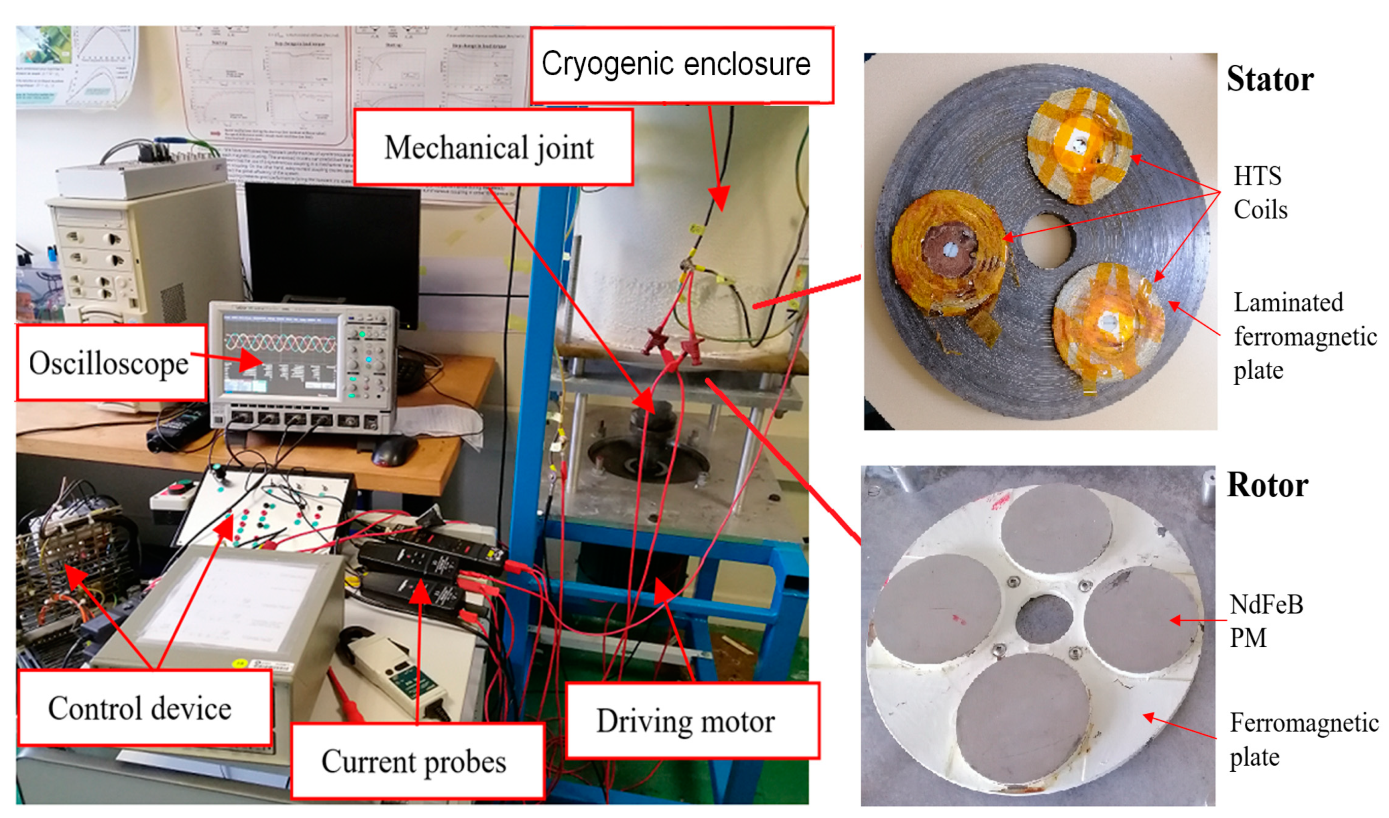
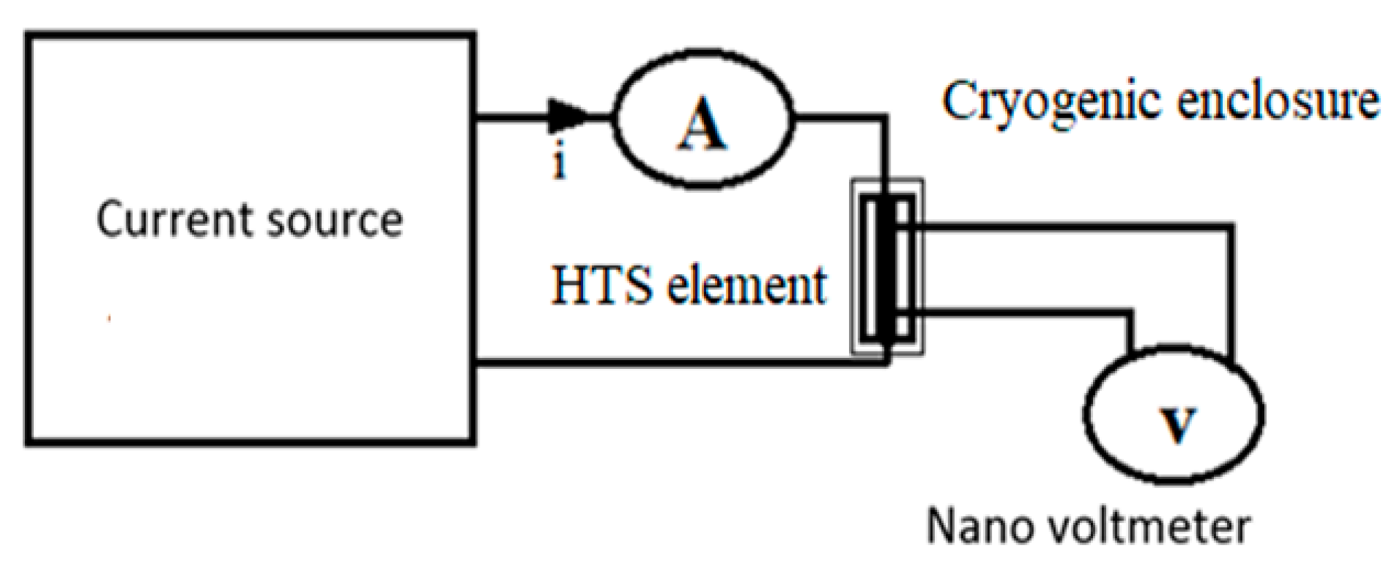
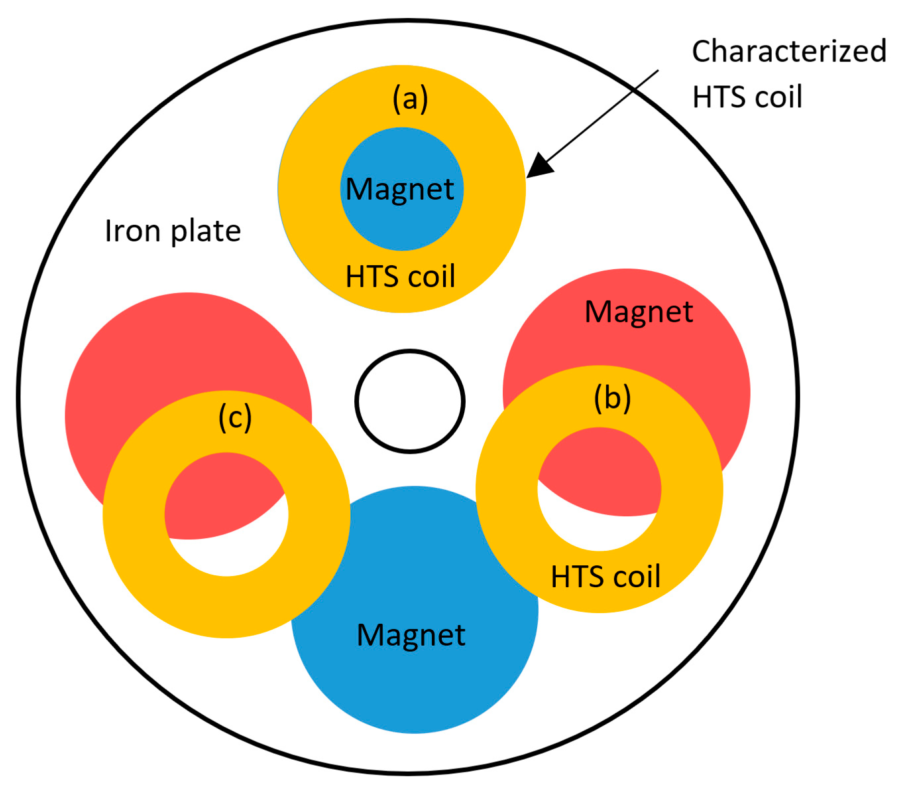
2. The HTS Synchronous Machine Prototype and Its Test Bench

With an external diameter of approximately 30 cm, the prototype is composed of a permanent magnet rotor and a stator carrying three-phase superconducting windings cooled with liquid nitrogen (Figure 1). The rotor consists of four permanent Nd-Fe-B ( Nd 2 Fe 14 B ) -type cylindrical magnets mounted on a ferromagnetic yoke at the middle radius, forming four magnetic poles (p = 2). The cylindrical yoke, made of E24 mild steel, is sized to avoid magnetic saturation. The superconducting armature constitutes three superconducting coils mounted on a Fe-Si ferromagnetic yoke, at the middle radius, in the air gap (absence of notches). The superconducting coils are made of an AC type DI-BSCCO (dramatically innovative BSCCO) tape manufactured by Sumitomo Electric. In such tape, the BSCCO filaments are twisted inside a silver matrix, presenting low AC losses [19]. The coils are of a pancake form, where the turns are insulated using Kapton film. The ferromagnetic yoke is laminated in the radial direction to limit eddy current losses. The machine is installed vertically and the superconducting armature is immersed in a cryostat filled with liquid nitrogen (77 K). The permanent magnet rotor is at room temperature, driven by an asynchronous motor powered by a variable frequency-controlled inverter.
The electric method is used to characterize the HTS coils, separately, inside the machine. The electric model, E(J), and the critical current (Jc) of the superconductor are characterized in DC using a direct current source and a nanovoltmeter, as presented in Figure 2. The characterized sample is supplied by a direct current, I, and the potential difference (U) across its terminals is measured. The critical electric field (Ec) is set to 1 μV/cm. The critical voltage (Uc) of the sample is the product of the critical electric field with the length between the voltage taps (L) and the critical current ( I c = J c × S ), where S is the tested sample section and Jc is the current giving the critical voltage [20]. The E(J) dependency is generally expressed using the power law given in Equation (1), where n is the creep exponent.
U = U c I I c ( B ) n E = E c J J c ( B ) n U = E × L ; I = J × S

3. Numerical Modeling

Experimental characterization using electrical methods, as described above, only allows us to measure global quantities (U, I) which are further used to determine local quantities (E, J) with the assumption of the uniformity of the distribution of both E and J. However, the local quantities can vary significantly due to the strong dependency of the critical current density (Jc) to the magnetic field (B). Modeling is thus necessary, and numerical methods are unavoidable in most cases, due to the complexity of the geometries and the nonlinear behavior of superconductors. In our works, volume integral methods have proved their efficiency to model such systems which are in multi-conductor configurations characterized by multiscale dimensions, where the air regions are consequent. Indeed, the volume integral methods allow us to discretize only the active parts of the modelled systems.
The magnetic vector potential (A) and the magnetic field (B) are evaluated using integral equations involving the volume and surface current densities ( J ,   k ) [21,22]:
A ( r ) = μ 0 Ω J ( r ) . G ( r , r ) d Ω + Γ k ( r ) . G ( r , r ) d Γ B ( r ) = μ 0 Ω J ( r ) G ( r , r ) d Ω + Γ k ( r ) G ( r , r ) d Γ
The surface current densities ( k ) are used to model permanent magnets and ferromagnetic materials, with finite linear and nonlinear permeabilities [22]. The method of images is used when the permeability is considered infinite, which is the case in this work.
The E(J) relation of the superconductor is modelled using power law (1), and the anisotropic dependency of the critical current density to the magnetic field is modeled using relation (3), where J c 0 is the zero field critical current density, and k , β and B 0 are parameters depending on the considered HTS.
J c ( B , B ) = J c 0 1 + k 2 B 2 + B 2 B 0 β
The ferromagnetic yokes are sized to avoid magnetic saturation; the superposition principle is then used for the magnetic field calculation. The PM rotor motion is modeled using a multi-static approach to evaluate the global quantities at different rotor positions.

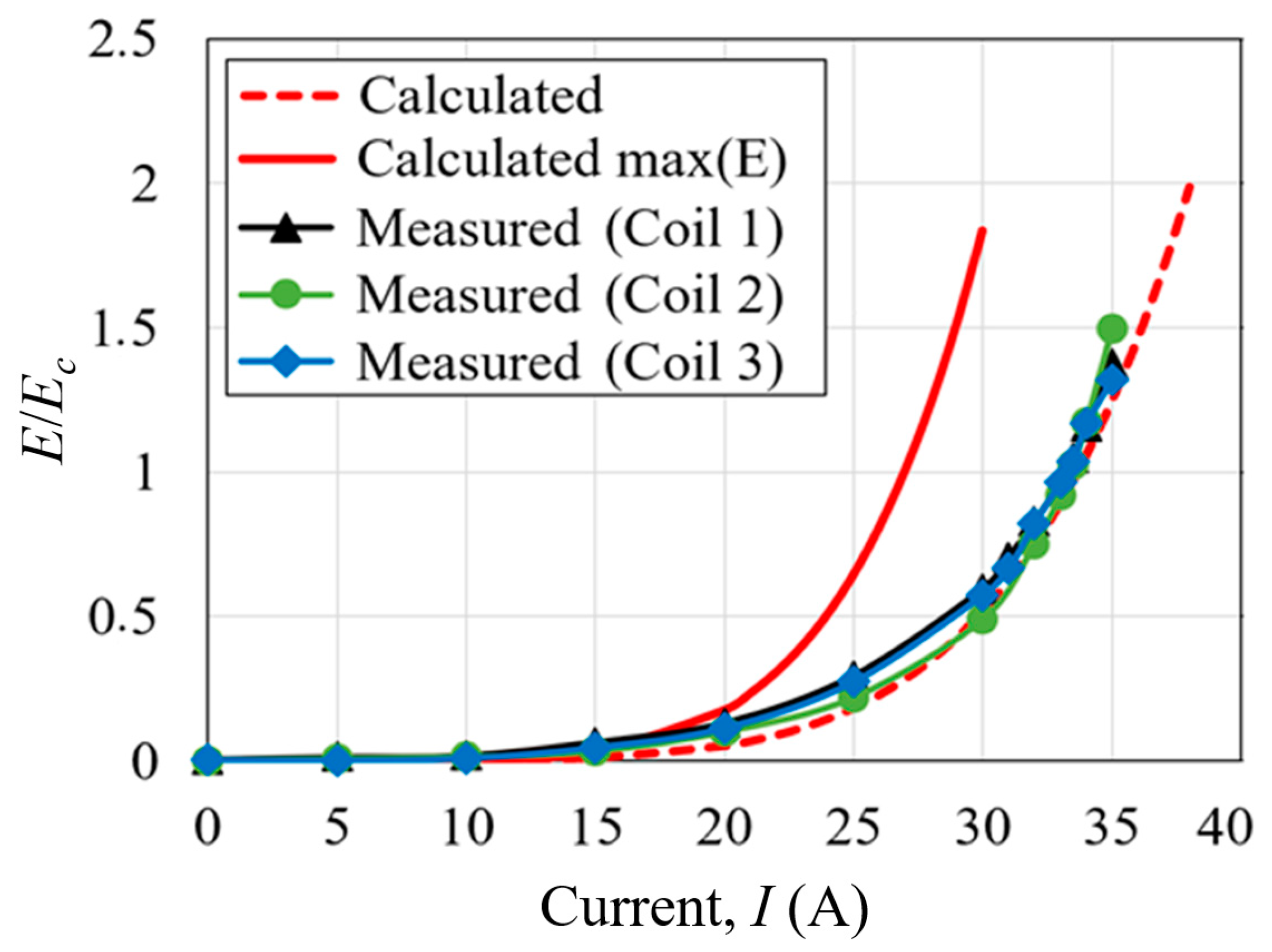
4. Results and Discussions

The specifications of the different parameters of the machine are given in Table 1. The U(I) curves are measured in the HTS coils inside the machine, in the configuration presented in Figure 3, corresponding to the worst case where the characterized coil is facing a permanent magnet. The coils (a, b, c) are fed with the currents Ia = I and Ib = Ic = −I/2, corresponding to a functioning point in a three-phase system. The coil (a), fed by the current I, is the one characterized. The results are presented in Figure 4. With a global criterion, the critical current is reduced to 33.7 A, while it is about 70 A for the tape constituting the coils. Using a local criterion (max E), the critical current density drops to about 27 A (obtained through simulations). Figure 5 shows the repartition and the magnitude of the electric field in the coil. As can be noticed, locally, the maximal value of the electric field in the coil corresponding to a current supply of 33.7 A is 3.5 times its critical value. A relatively large difference is obtained between the values of the critical current obtained using the local and global criteria, highlighting the importance of the modeling.
The no-load voltage obtained in a coil (phase) is shown in Figure 6. The large airgap filters space harmonics, providing a quasi-sinusoidal voltage, despite the structure of the machine. The magnitude of the no-load voltage is proportional to the frequency (the rotor speed). The Behn-Eschenburg model, based on the assumption of the first space harmonic, described in Figure 7, can thus be used to study the behavior of the synchronous generator, where Rs and Xs are the resistance and reactance of a stator phase (one coil in this case). Both are nonlinear, depending on the current. The resistance Rs accounts for all the losses that occur in the superconducting coils [24]. The dependence of Xs on the current is related to the nonlinear behavior of both the superconductor forming the coil, and that of the ferromagnetic parts. Due to the large distance between the HTS coils, they are magnetically decoupled. For low current values, the self-inductance of a coil is of about 3.7 mH. Considering a resistive load, the load voltage variation with the load current is given in Figure 8, for a rotating speed of 750 rpm, corresponding to a frequency of 25 Hz. The measurements fit well with the Behn-Eschenburg model results, where the resistance Rs is neglected.
The resistance Rs is thus much lower than the reactance, and for low values of the current, it can be neglected. This is also highlighted in Figure 9, representing the time evolution of the short-circuit current in the machine in response to a variation in the frequency (rotation speed of the rotor). As we can see, a time constant of several seconds is observed. A short-circuit fault could therefore be very dangerous for such a machine. The association of the machine, in motor mode, with a power converter for its control can also be problematic.
The evaluation of AC losses is of major interest for this type of application. Unfortunately, the measurement of AC losses in the rotating machine environment is challenging and remains a technical issue to overcome.
With the HTS coils being decoupled, we measured the AC losses in a coil above a ferromagnetic plate, as shown in Figure 10a. The coil is fed with a sinusoidal current and the voltage in its terminal is measured with voltage taps located as far as possible from the current leads. Figure 10b show the evolution of the total AC losses with the current, including the losses in the iron plate, at a frequency of 10 Hz. The separation between the iron losses and the AC losses in the HTS coil is made by using a copper coil of the same structure [23,24,25].
As expected, the iron losses are much greater than the AC losses in the HTS coils. The measurements are made at a frequency of 10 Hz, and one can reasonably extrapolate these results to higher frequencies for which the hysteresis losses remain predominant (hysteresis losses are proportional to the frequency).
The presence of the permanent magnets will obviously affect the AC losses in the HTS coils by decreasing the critical current. However, this effect is moderated by the structure of the machine, where the magnetic field is mainly parallel to the tape surfaces (superconducting plane) due to its canalization by the iron plates of the stator and the rotor.
For an estimation of the efficiency, one has to also consider the eddy current losses in the permanent magnets caused by the magnetic reaction of the HTS coils. However, they are expected to be lower than the iron losses. Given this, for a current of 20 A and a frequency of 20 Hz, one can expect a rated power of about 600 W, with total electrical losses below 5 W. To evaluate the overall efficiency, the mechanical losses on the machine bearings also have to be considered.
Another way to estimate the electrical losses in the superconducting part is to evaluate the elements of the electric model given in Figure 7. The results of the short-circuit test provide a time constant of the current evolution in a coil, which is the ratio between the inductance and the resistance Rs. The resistance, and thus the losses, can be deduced from the time constant if the inductance is correctly evaluated. This also needs a correct determination of the starting current. The results of the short-circuit test provide a time constant of about 15 s. With the inductance of a coil being about 3.7 mH, the resistance Rs is then about 0.25 mΩ, giving a power loss of 0.1 W in the coil for a current of I = 20 A, which is coherent with the measurement presented in Figure 10b.
Notice that Rs accounts only for the losses in the superconductor. To consider the hysteresis losses in the iron parts, one may complete the Behn-Eschenburg model by adding an equivalent resistance (Rf) parallel to the voltage source, as presented in Figure 11.

5. Conclusions

In this work, we presented the experimental tests carried out on a laboratory-scale prototype of an axial flux synchronous machine with a superconducting armature. Numerical and experimental approaches are combined to characterize the machine. The obtained results are promising, highlighting the possibility of the use of high-temperature superconductors as armatures in electrical machines. The important electrical time constant of the machine makes short-circuit faults very dangerous in this type of machine, and can limit the possibilities of association with a frequency converter for a control in motor mode. The measurement of AC losses in the rotating machine environment remains a technical issue to overcome. An original approach is proposed for their estimations.

Author Contributions

Conceptualization, Y.S. and H.M.; methodology, Y.S. and H.M.; software, Y.S. and H.M.; validation, Y.S.; formal analysis, Y.S. and H.M.; investigation, Y.S. and H.M.; writing—original draft preparation, H.M.; writing—review and editing, H.M.; visualization, H.M.; supervision, H.M. All authors have read and agreed to the published version of the manuscript.

Funding

This research received no external funding.

Data Availability Statement

No new data were created.

Conflicts of Interest

The authors declare no conflict of interest.

References

  1. Haran, K.S.; Kalsi, S.; Arndt, T.; Karmaker, H.; Badcock, R.; Buckley, B.; Haugan, T.; Izumi, M.; Loder, D.; Bray, J.W.; et al. High power density superconducting machines—Development status and technology roadmap. Supercond. Sci. Technol. 2017, 30, 123002. [Google Scholar] [CrossRef]
  2. Nick, W.; Frank, M.; Klaus, G.; Frauenhofer, J.; Neumuller, H.-W. Operational experience with the world’s first 3600 rpm 4 MVA generator at Siemens. IEEE Trans. Appl. Supercond. 2007, 17, 2030–2033. [Google Scholar] [CrossRef]
  3. Gamble, B.; Snitchler, G.; MacDonald, T. Full Power Test of a 36.5 MW HTS Propulsion Motor. IEEE Trans. Appl. Supercond. 2011, 21, 1083–1088. [Google Scholar] [CrossRef]
  4. Song, X.; Mijatovic, N.; Bührer, C.; Kellers, J.; Wiezoreck, J.; Krause, J.; Pütz, H.; Hansen, J.; Rebsdorf, A.V. Experimental Validation of a Full-Size Pole Pair Set-Up of an MW-Class Direct Drive Superconducting Wind Turbine Generator. IEEE Trans. Energy Convers. 2020, 35, 1120–1128. [Google Scholar] [CrossRef]
  5. Song, X.; Bührer, C.; Brutsaert, P.; Ammar, A.; Krause, J.; Bergen, A.; Winkler, T.; Dhalle, M.; Hansen, J.; Rebsdorf, A.V.; et al. Ground Testing of the World’s First MW-Class Direct-Drive Superconducting Wind Turbine Generator. IEEE Trans. Energy Convers. 2020, 35, 757–764. [Google Scholar] [CrossRef]
  6. Song, X.; Bührer, C.; Mølgaard, A.; Andersen, R.S.; Brutsaert, P.; Bauer, M.; Hansen, J.; Rebsdorf, A.V.; Kellers, J.; Winkler, T.; et al. Commissioning of the World’s First Full-Scale MW-Class Superconducting Generator on a Direct Drive Wind Turbine. IEEE Trans. Energy Convers. 2020, 35, 1697–1704. [Google Scholar] [CrossRef]
  7. Xian, W.; Yan, Y.; Yuan, W.; Pei, R.; et Coombs, T.A. Pulsed field magnetization of a high temperature superconducting motor. IEEE Trans. Appl. Supercond. 2011, 21, 1171–1174. [Google Scholar] [CrossRef]
  8. Berger, K.; Kapek, J.; Colle, A.; Grzesik, M.S.B.; Lubin, T.; Lévêque, J. 3-D Modeling of Coils for Pulsed Field Magnetization of HTS Bulk Pellets in an Electrical Machine. IEEE Trans. Appl. Supercond. 2018, 28, 6801205. [Google Scholar] [CrossRef]
  9. Alhasan, R.; Lubin, L.; Adilov, Z.M.; Lévêque, J. A New Kind of Superconducting Machine. IEEE Trans. Appl. Supercond. 2016, 26, 5203604. [Google Scholar] [CrossRef]
  10. Colle, A.; Lubin, L.; Ayat, S.; Gosselin, O.; Lévêque, J. Analytical Model for the Magnetic Field Distribution in a Flux Modulation Superconducting Machine. IEEE Trans. Magn. 2019, 55, 9000415. [Google Scholar] [CrossRef]
  11. Sekiguchi, D.; Nakamura, T.; Misawa, S.; Kitano, H.; Matsuo, T.; Amemiya, N.; Ito, Y.; Yoshikawa, M.; Terazawa, T.; Osamura, K.; et al. Trial Test of Fully HTS Induction/Synchronous Machine for Next Generation Electric Vehicle. IEEE Trans. Appl. Supercond. 2012, 22, 5200904. [Google Scholar] [CrossRef]
  12. Kovalev, K.; Ivanov, N.; Zhuravlev, S.; Nekrasova, J.; Rusanov, D.; Kuznetsov, G. Development and testing of 10 kW fully HTS generator. J. Phys. Conf. Ser. 2020, 1559, 012137. [Google Scholar] [CrossRef]
  13. Sugimoto, H.; Tsuda, T.; Morishita, T.; Hondou, Y.; Takeda, T.; Togawa, H.; Oota, T.; Ohmatsu, K.; Yoshida, S. Development of an Axial Flux Type PM Synchronous Motor With the Liquid Nitrogen Cooled HTS Armature Windings. IEEE Trans. Appl. Supercond. 2007, 17, 1637–1640. [Google Scholar] [CrossRef]
  14. Song, P.; Qu, T.; Yu, X.; Li, L.; Gu, C.; Li, X.; Wang, D.; Hu, B.; Chen, D.; Han, Z. Loss measurement and analysis for the prototype generator with HTS stator and permanent magnet rotor. Phys. C Supercond. 2013, 494, 225–229. [Google Scholar] [CrossRef]
  15. Qu, T.; Song, P.; Yu, X.; Gu, C.; Li, L.; Li, X.; Wang, D.; Hu, B.; Chen, D.; Zeng, P.; et al. Development and testing of a 2.5 kW synchronous generator with a high temperature superconducting stator and permanent magnet rotor. Supercond. Sci. Technol. 2014, 27, 044026. [Google Scholar] [CrossRef]
  16. Messina, G.; Tamburo De Bella, E.; Morici, L. HTS Axial Flux Permanent Magnets Electrical Machine Prototype: Design and Test Results. IEEE Trans. Appl. Supercond. 2019, 29, 5200605. [Google Scholar] [CrossRef]
  17. Grilli, F.; Kario, A. How filaments can reduce AC losses in HTS coated conductors: A review. Supercond. Sci. Technol. 2016, 29, 083002. [Google Scholar] [CrossRef]
  18. Statra, Y.; Menana, H.; Douine, B.; Lubin, T. Axial-Field Synchronous Machine With HTS Armature Windings: Realization and Preliminary Tests. IEEE Trans. Appl. Supercond. 2022, 32, 5200405. [Google Scholar] [CrossRef]
  19. Kikuchi, M.; Ayai, N.; Ishida, T.; Tatamidani, K.; Hayashi, K.; Kobayashi, S.; Ueno, E.; Yamazaki, K.; Yamade, S.; Takaaze, H.; et al. Development of New Types of DI-BSCCO Wire. SEI Tech. Rev. 2008, 66, 73–79. [Google Scholar]
  20. Statra, Y.; Fawaz, S.; Menana, H.; Douine, B. Experimental Electromagnetic Characterization of High Temperature Superconductors Coils Located in Proximity to Electromagnetically Active Materials. Fluid Dyn. Mater. Process 2022, 18, 1529–1537. [Google Scholar] [CrossRef]
  21. Statra, Y.; Menana, H.; Belguerras, L.; Douine, B. A volume integral approach for the modelling and design of HTS coils. Compel 2019, 38, 1133–1140. [Google Scholar] [CrossRef]
  22. Statra, Y.; Menana, H.; Douine, B. Integral Modeling of AC Losses in HTS Tapes with Magnetic Substrates. IEEE Trans. Appl. Supercond. 2022, 32, 5900407. [Google Scholar]
  23. Li, Y.; Jiang, Z.; Sidorov, G.; Koraua, R.; Sogabe, Y.; Amemiya, N. AC Loss Measurement in HTS Coil Windings Coupled with Iron Core. IEEE Trans. Appl. Supercond. 2019, 29, 4701805. [Google Scholar]
  24. Fukui, S.; Tsukamoto, S.; Nohara, K.; Ogawa, J.; Sato, T.; Nakamura, T. Study on AC Loss Reduction in HTS Coil for Armature Winding of AC Rotating Machines. IEEE Trans. Appl. Supercond. 2016, 26, 5203705. [Google Scholar] [CrossRef]
  25. Fukui, S.; Ogawa, J.; Takahashi, J.; Kobu, Y.; Sato, T.; Nakamura, T. Study on AC Loss Characteristics of 3-Phase HTS Coils with Iron Core and Its Reduction. IEEE Trans. Appl. Supercond. 2019, 29, 8201305. [Google Scholar] [CrossRef]
Figure 1. The HTS synchronous machine prototype and its test bench.
Condensedmatter 08 00094 g001
Figure 2. DC characterization of the HTS coils.
Condensedmatter 08 00094 g002
Figure 3. Position of the characterized coil in the machine, in the DC characterization.
Condensedmatter 08 00094 g003
Figure 4. Measured and calculated E(I) curves of the HTS coils.
Condensedmatter 08 00094 g004
Figure 5. Repartition and magnitude of the electric field in the characterized coil, corresponding to the computed and measured critical currents.
Condensedmatter 08 00094 g005
Figure 6. Voltage waveform and its harmonics for a rotational speed of 600 rpm.
Condensedmatter 08 00094 g006
Figure 7. The Behn-Eschenburg model of the machine based on the assumption of the first space harmonic.
Condensedmatter 08 00094 g007
Figure 8. Load voltage variation with the load current for a resistive load, at a rotating speed of 750 rpm, corresponding to a frequency of 25 Hz.
Condensedmatter 08 00094 g008
Figure 9. Evolution of the short-circuit current measured in response to a variation in the rotor speed.
Condensedmatter 08 00094 g009
Figure 10. Evaluation of the AC losses in an HTS coil above an iron plate. (a) The HTS coil structure. (b) Evolution of the measured AC losses with the applied current for a frequency of f = 10 Hz.
Condensedmatter 08 00094 g010
Figure 11. The Behn-Eschenburg model of the machine based on the assumption of the first space harmonic, considering the iron losses.
Condensedmatter 08 00094 g011
Table 1. Parameters specifications [23].
ParameterValue
BSCCO tapeIc @ 77 K (self-field)70 A
Width/Thickness2.8/0.33 mm
HTS coilsIc @ 77 K (self-field)43.3 A
Number of turns63
Inner/outer radii25/50 mm
Thickness3.1 mm
Nd-Fe-B magnetsRemanence1.25 T
Radius/Thickness50/10 mm
Armature iron yokeThickness20 mm
Inner/outer radii25/152 mm
Rotor iron yokeThickness10 mm
Inner/outer radii25/140 mm
Disclaimer/Publisher’s Note: The statements, opinions and data contained in all publications are solely those of the individual author(s) and contributor(s) and not of MDPI and/or the editor(s). MDPI and/or the editor(s) disclaim responsibility for any injury to people or property resulting from any ideas, methods, instructions or products referred to in the content.

