1. Introduction
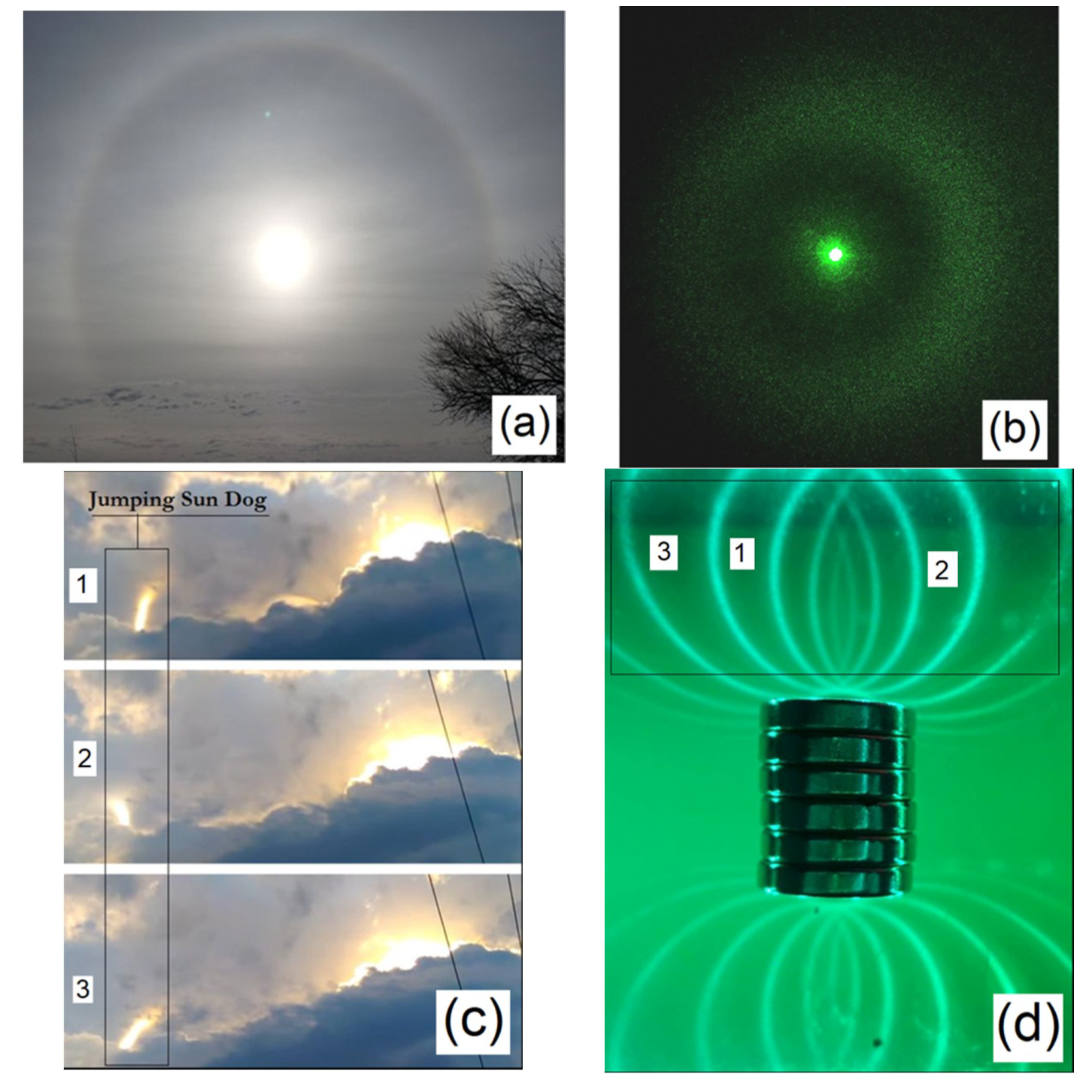
The observation of atmospheric optical phenomena has caused a sense of wonder in many people throughout history, such as the sundogs, crown flashes, parhelic circles, light pillars, or the miracle of the sun. All of these phenomena are rare, and we can hardly predict their occurrence. However, the technological development that allows for the availability of cameras and camcorders, associated with the dissemination of the recordings of these phenomena on social networks, allows us to try to give a plausible explanation for these rare events. For example, the crown flash in
Figure 1 in meteorology is an atmospheric optical phenomenon that consists of a luminous column that moves near dense clouds during the day [
1,
2]. These images of this atypical event were obtained from a YouTube user’s video (QuadM13) observed at Greenwood, Indiana, USA [
3], on the same day that another YouTube user’s video from Shelbyville, Indiana, USA (Chris Mercer) captured another video of this jumping sundog on June 12, 2015 at 6:39 pm CDT [
4], with a distance of almost 30 km between the two.
Clouds can be an example of a complex fluid [
5] that changes constantly due to atmospheric conditions, in which a gas phase contains structures such as tiny ice crystals in motion. The existence of such structure for this kind of system distinguishes a cloud from a simple fluid, with properties which allow self-organization in the presence of an electric field or air flow. In the case of a crown flash or jumping sundogs, one possible explanation for this phenomenon to occur is that sun light is interacting through ice crystals above the clouds in the presence of an oscillating electrical field, while in the case of light pillars, the spatial distribution of particles inside this complex fluid creates the observable light pattern.
Thus, these properties in such a natural environment, which cause so much astonishment in people, are the result of the emergence of light patterns in a complex system on a scale of huge proportions. This feeling of wonder can lead to a sense of transcendence, inducing in many people a deep feeling of connection with nature, but sometimes leads to classification of these phenomena as miracles, omens, conspiracy theories or even an extraterrestrial manifestation, as we can see in the comments made by several users on the videos mentioned above. In this way, it is interesting to carry out relatively simple and accessible experiments to demonstrate some of the main concepts present in these phenomena.
The use of analogous systems can facilitate the presentation and interpretation of these phenomena. See, for example, the formation of the solar halo in
Figure 1a and the formation of the laser halo using ferrofluids in
Figure 1b. Even considering that the first case is mainly related to geometric optics, while the second case is associated with light diffraction, both systems show how light can be projected around the light source due to its interaction with particles suspended in a fluid. Another case is the oscillating light flash in
Figure 1c, which can be associated with different states of the static light patterns in
Figure 1d, if we consider that a characteristic light pattern can respond to changes in the state of some type of field that controls the movement of particles that are interacting with light, as in the case of
Figure 1d, showing some of these possible field states for the same light source placed in different positions, simultaneously. An important result that can be obtained with all of this is the existence of conditions that allow the emergence of a self-organization that manifests itself through the observation of an optical phenomenon on an atmospheric scale.
In this way, this work presents some plausible explanations for some of these events and connects them to other interesting systems that are based in the same concepts but in different scales, using some principles of physics and material science. In the next section, we present our method; after that, we explore the phenomenon of light pillars and compared them with the light patterns in gems. In
Section 4, we investigate the polarization patterns of ferrofluid and related patterns in crystals. Finally, we present our conclusions in
Section 5.
2. Materials and Methods
In order to simulate some optical phenomena, we have used materials with magneto-optical properties. We have used a thin film of ferrofluid subjected to an external magnetic field (Ferrolens). When light interacts with this thin film of ferrofluid, it undergoes different effects, and we can observe some analogies between the atmospheric phenomena and the magneto-optical light patterns, which intend to show some principles involved, giving a sense of how well the idealizations treated apply to the atmospheric systems [
1,
6,
7].
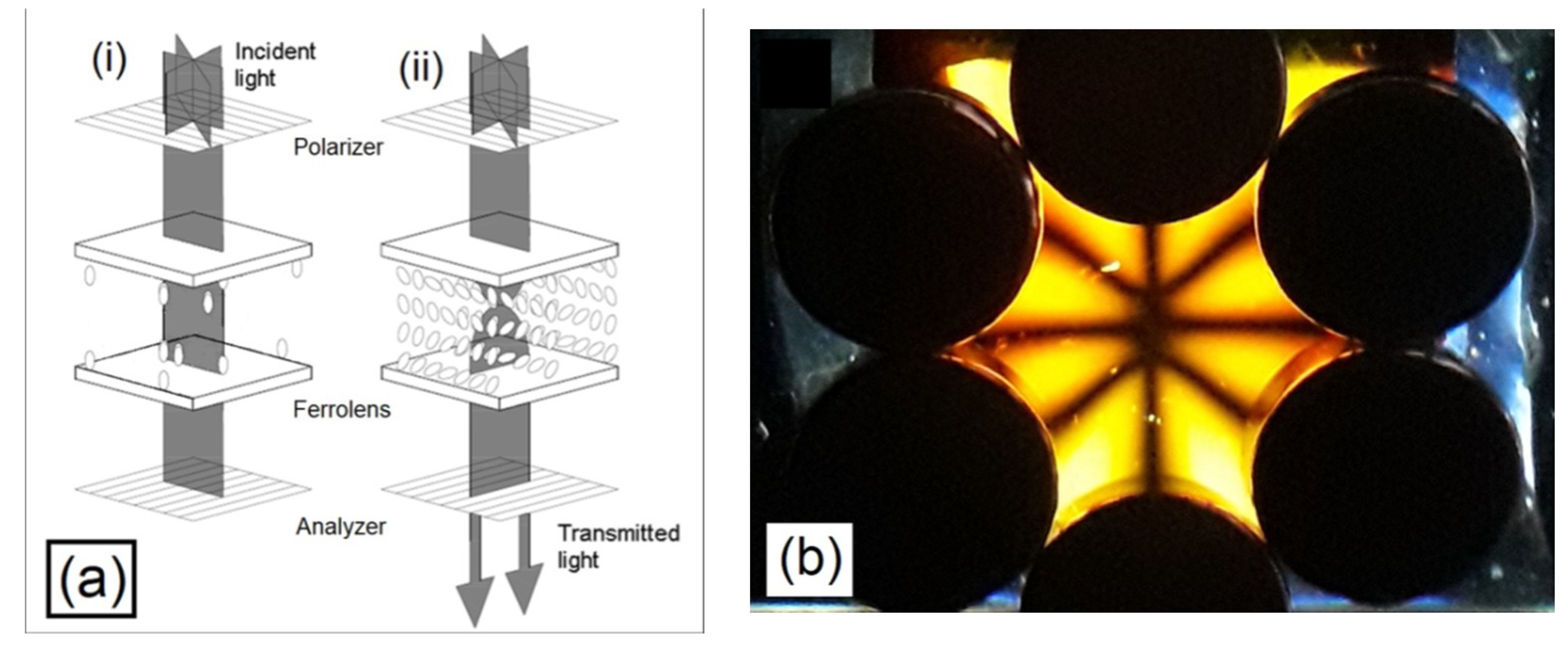
In addition to this, we also have explored the optical properties of gems, such as the light patterns present in the cat’s eye effect and light polarization patterns obtained from gemology, comparing the formation of patterns in crystals with the light polarization patterns in ferrofluids in
Figure 2.
We also have used magnetostatic equations to find the solutions related to the light patterns obtained from the thin films of ferrofluid, using treatments based on the idea of magnetic charges, enabling us to use the representation of magnetic scalar potentials, because when an external magnetic field is applied to the ferrofluid, the magnetic moments of the nanoparticles in the ferrofluid are oriented along the external magnetic field. Although the magnetic charges are a useful abstraction, with no physical existence, they are analogous to the case of electric charges in electrostatic, making the analysis of the physical system simpler; to deal with scalar potentials is much more intuitive than the magnetostatic case of Amperian currents, which leads to the vector potential. In this way, considering the magnetic field
BM produced by a magnetic field
ρM:
where
ρM is a fictitious magnetic charge. Following this analogy, we introduce the magnetic scalar potential
ϕM, defined by the relation:
To simulate the magnetic field around the magnets, we have used the computer code Pic2mag [
8].
Due to the interaction between the magnetic field and the ferrofluid, some ordered structures are formed, and consequently, there is a chain formation of magnetic particles along the magnetic field, similar to the case where there are iron fillings in the presence of a magnetic field. When light interacts with these structures, it is scattered, forming light patterns. The same principle occurs when light interacts with the ice crystals in the atmosphere [
6,
7].
We have used different types of setups to explore the properties of the light patterns in ferrofluids and compare them with atmospheric patterns. We can observe patterns in the plane of
Figure 1d directly in the thin film of ferrofluid [
1,
9,
10,
11], in which the source of lights consists of LEDs. The second case is laser transmission through the ferrofluid [
1,
10] subjected to a magnetic field in
Figure 1b. The third case is the light polarization presented in
Figure 2b [
10,
11]. We were inspired to compare the light patterns of gems and ferrofluids by a demonstration at the Geo Gallery, Smithsonian Natural Museum of Natural History in Washington, D.C., USA [
12], which consisted of grids of lines with one white LED as the source of light.
3. Light Pillars and Chatoyancy
Initially, we will explore the interesting case of light pillars, in which columns of light emanate from a light source, because the ice crystals in the atmosphere reflect the source of light towards the viewer, as can be seen in
Figure 3a,b [
6]. The same principle of these bands of light can be found at the phenomenon known as chatoyancy, where we can see narrow bands of light within gemstones, like the one in
Figure 3c.
We can find gemstones with single bands patterns like the slits in cat’s eye, but on other gemstones, the patterns form stars with multiple rays. These beautiful optical effects are created in many cases by light reflected in beams of needle-like crystals, or light reflected in tiny hollow tubes within a crystal.
Yet, what is the physical concept which gives the connection between these two phenomena? What are the properties in the atmosphere behind these light pillars which make possible the emergence of these patterns? The answer of the first question is the law of reflection, while the answer for the second question suggests the existence of a flat hexagonal plate assembly of ice crystals filling the space between the light sources and the viewer. The existence of these floating ice plates depends on several atmospheric factors that vary during the year, such as the temperature and the humidity, but can remain present for a period of time, which allows the observation of the phenomenon. For example, the formation of ice needles occurs mainly within the temperature range from −10 °C to 5 °C, and for the water vapor density around 0.15 g/m
3, outside of the region of water saturation, according to the Nakaya diagram [
12] of the shapes of ice crystals. In the case of the formation of plates, we have found in the diagram previously cited that the temperature is around −15 °C and the water vapor density is 0.03 g/m
3, inside the region of water saturation. There is also a dynamic balance between the formation and falling of these ice plates filling the space between the light source and the observer from the ground level, and go upwards, creating a complex fluid in motion.
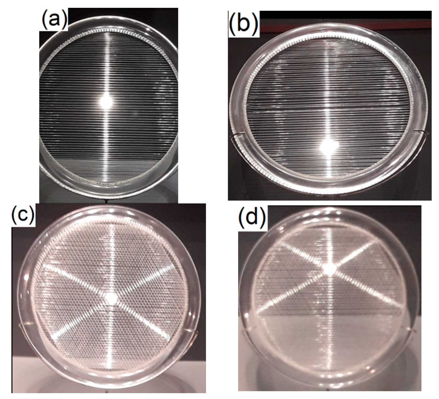
One simple experiment showing this optical effect of the light pillars and chatoyancy [
13] can be seen in
Figure 4a, when light reflects off parallel wires on the screen, creating a single band of light. In
Figure 4b, we can see a six-rayed star, since the source of light is reflecting in wires aligned in three directions. In
Figure 4c,d, we can see the two cases from a different perspective.
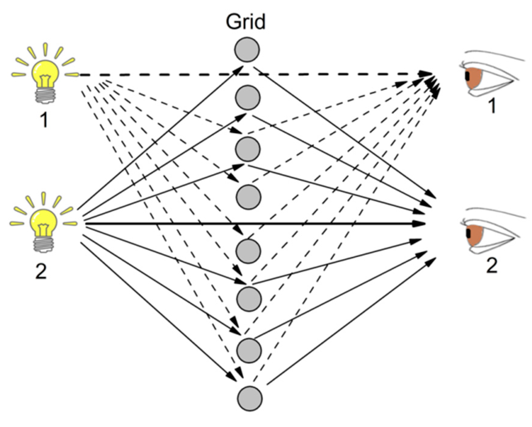
From the point of view of geometric optics, this effect is explained by the law of reflection in
Figure 5 in the case of chatoyancy, because the reflection still occurs if the light source and the viewer are at the same side of the grid. In the specific case of chatoyancy, there are microscopic acicular inclusions in some elbaite crystals forming the grid.
It is interesting to note that the effect is still present if the dimensions of the grid are changed, so that the physical properties of light have to be represented in the realm of physical optics. The light scattering will follow similar patterns. This transition is valid in the case of gems or in the case of the ice crystals. There are some important results that we can obtain from this diagram, as for example, from the point of view of the observer, the image of the source of light will be in the direction of the streak of light, no matter the position of the observer, if the grid is normal to the direction of the light propagation. In the case of oblique incidence of light on the grid elements, the source of light will still be in the light streak, but this light streak will not be necessarily be a straight line, but a curve like a parabola or a circle. For triangular or hexagonal structures, the light patterns may have the crossing of some lines as in the case of
Figure 4c,d, as discussed in some of our previous papers [
6,
7]. This effect, called asterism, can be observed in the sapphire “Star of Asia” [
14] at the Smithsonian Museum, because sapphires are a gem variety of the mineral corundum. This pattern of a six-rayed star forms because the titanium atoms are trapped within the growing corundum crystal, forming needlelike crystals of the mineral rutile, oriented in three directions.
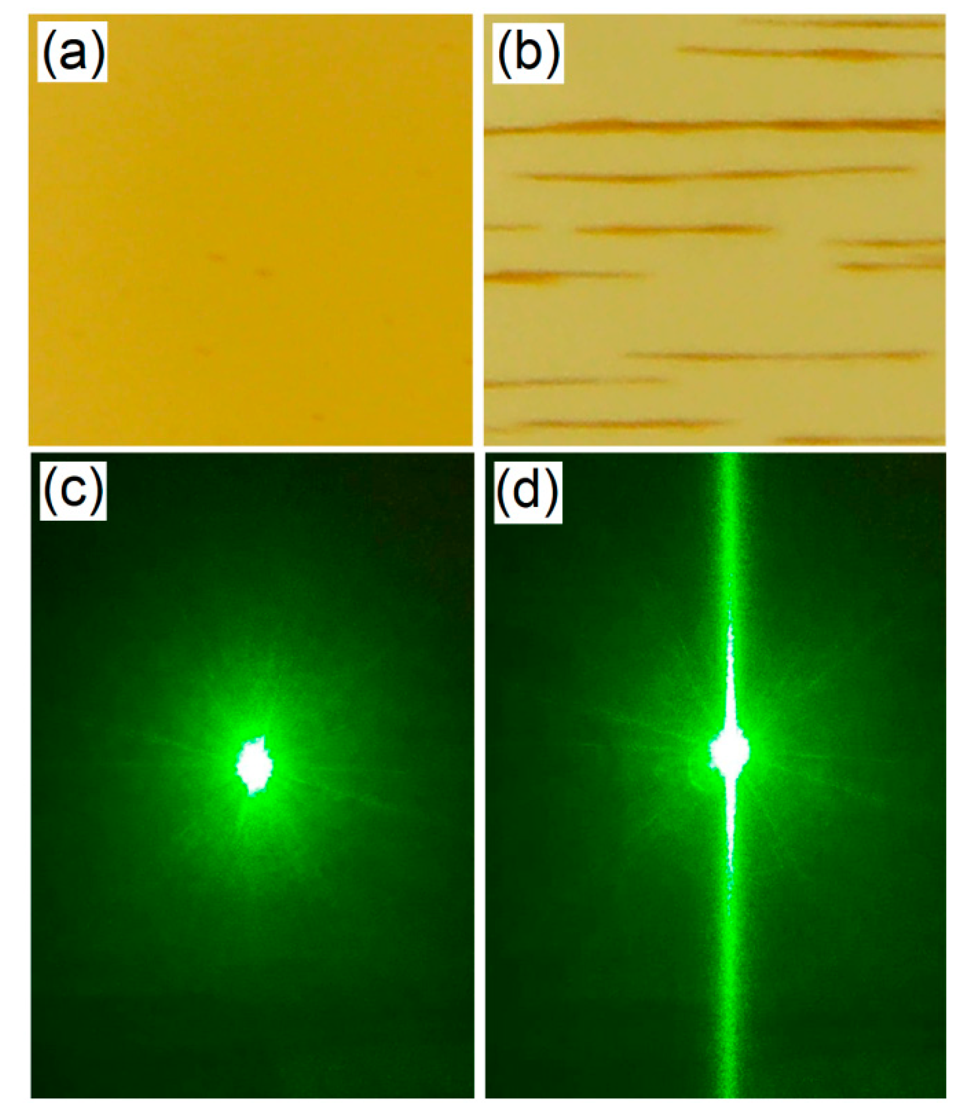
A similar effect can be observed using a thin film of ferrofluid subjected to a magnetic field and a laser beam, as is shown in
Figure 6. With no magnetic field, the ferrofluid has the brownish aspect of
Figure 6a, and in
Figure 6c, we see the laser projected on a screen after going through this thin film of ferrofluid. When a magnetic field of 300 gauss is applied, we can observe the formation of needlelike structures in
Figure 6b. The laser undergoes diffraction when it passes through the ferrofluid subjected to this magnetic field, as we can see in
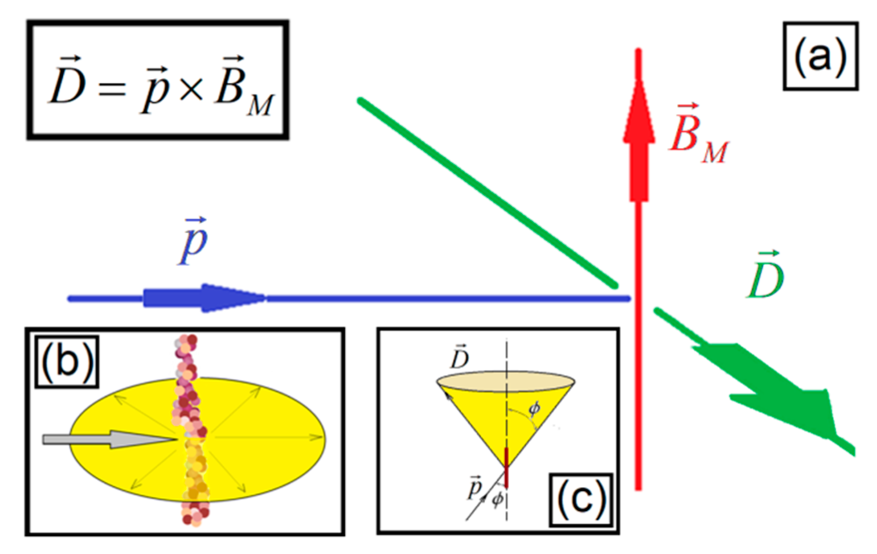
Figure 6d. The diagram of
Figure 7a represents the effect of the laser beam associated with the vector
p hitting the nanoneedle aligned with the magnetic field
BM, creating the diffraction
D:
According to the Geometrical Theory of Diffraction [
6,
7], when a light beam hits a needlelike structure, there is a cone of diffracted rays with the cross section that obeys the equation:
where
K is the diffraction coefficient,
r is the distance between the ferrofluid and the screen, and
k = 2π/
λ is the wave number of the incident field with wavelength
λ. Considering the
z coordinate of the polar system for the ferrofluid needle axis aligned with the magnetic field
BM, a conical scattering is observed instead of the circle scattering of
Figure 6b. The tilt between the incident vector
p and the axis of the nanoneedle is
ϕ, with the light being scattered along the surface of a cone with an apical angle of (180° − 2
ϕ), as is shown in
Figure 6c. We have explored these effects and compared them to the parhelic circle, a type of halo observed during the day in some weather conditions [
6].
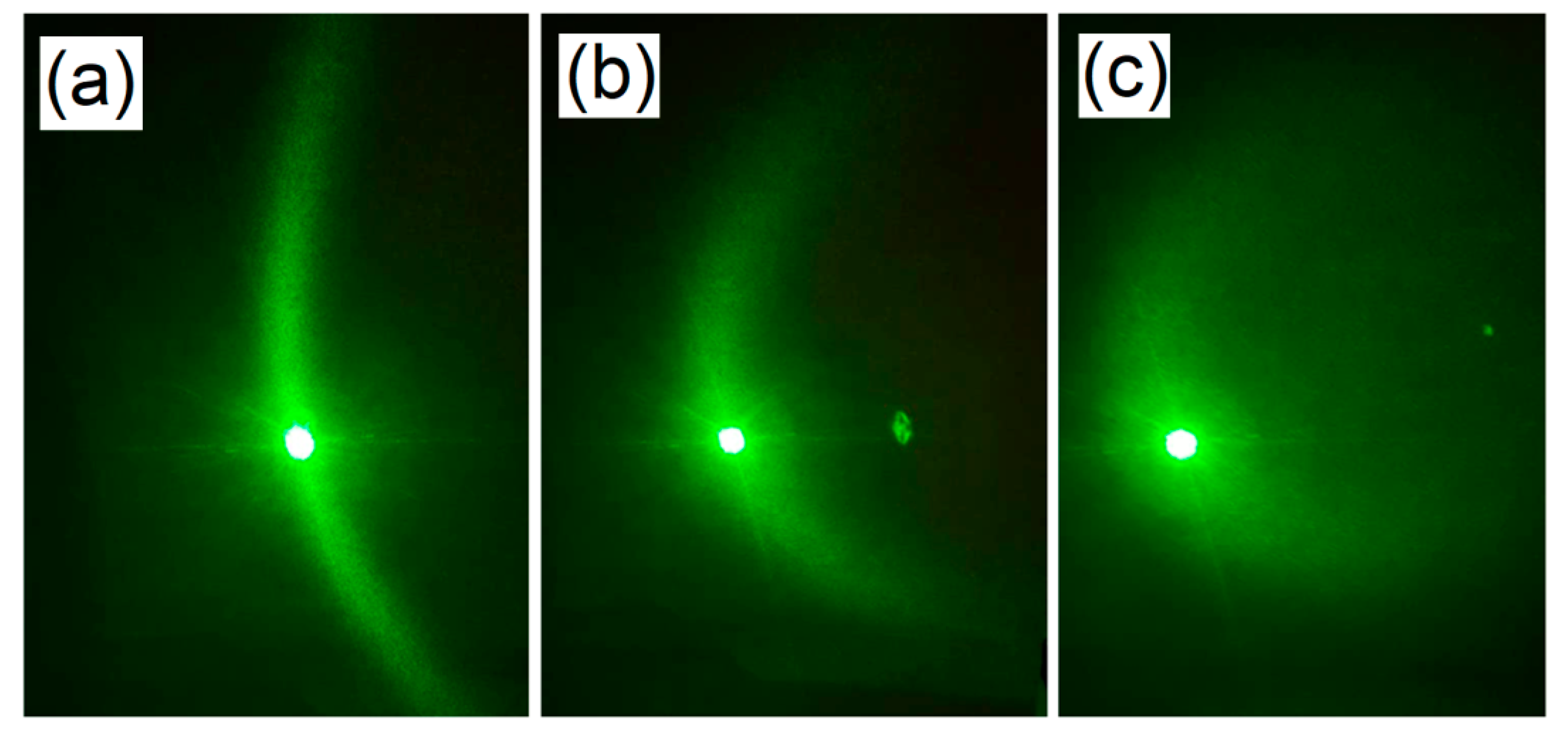
In other words, the light scattering in the ferrofluid is similar to the one observed in a cylindrical rod-like structure along the direction of the propagation, giving rise to the formation of curved light patterns [
6,
7]. We can observe this effect of light scattering hitting obliquely the needlelike structures of ferrofluids in
Figure 7. This mechanism is like the one observed in the grids of
Figure 4 related with the cat’s eye effect, and similar to same case of light scattering in ice crystals in the case of the jumping sundogs [
2]. When the magnetic field in ferrofluids or the electric field in clouds changes their orientation, we have the motion of the light pattern of the jumping sundogs, or the jumping laserdogs [
1] of
Figure 8, in the case of ferrofluid. The use of ferrofluids in this work reinforces some interesting properties present in our system. For example, the optical response of a thin film containing ferrofluid is not linear, as was already reported in our previous work [
10], such as the birefringence shown in
Figure 3 of the previous reference. Besides the birefringence or retardance, the magneto-optics of ferrofluids could involve Faraday rotation, the Kerr effect, and linear dichroism. If we compare
Figure 1d with
Figure 6d, we can see that the light source has quite different relative positions with respect to diffracted light. While in the first case, the diffracted light is around the laser, in the second case, the diffracted light emanates directly from the laser beam.
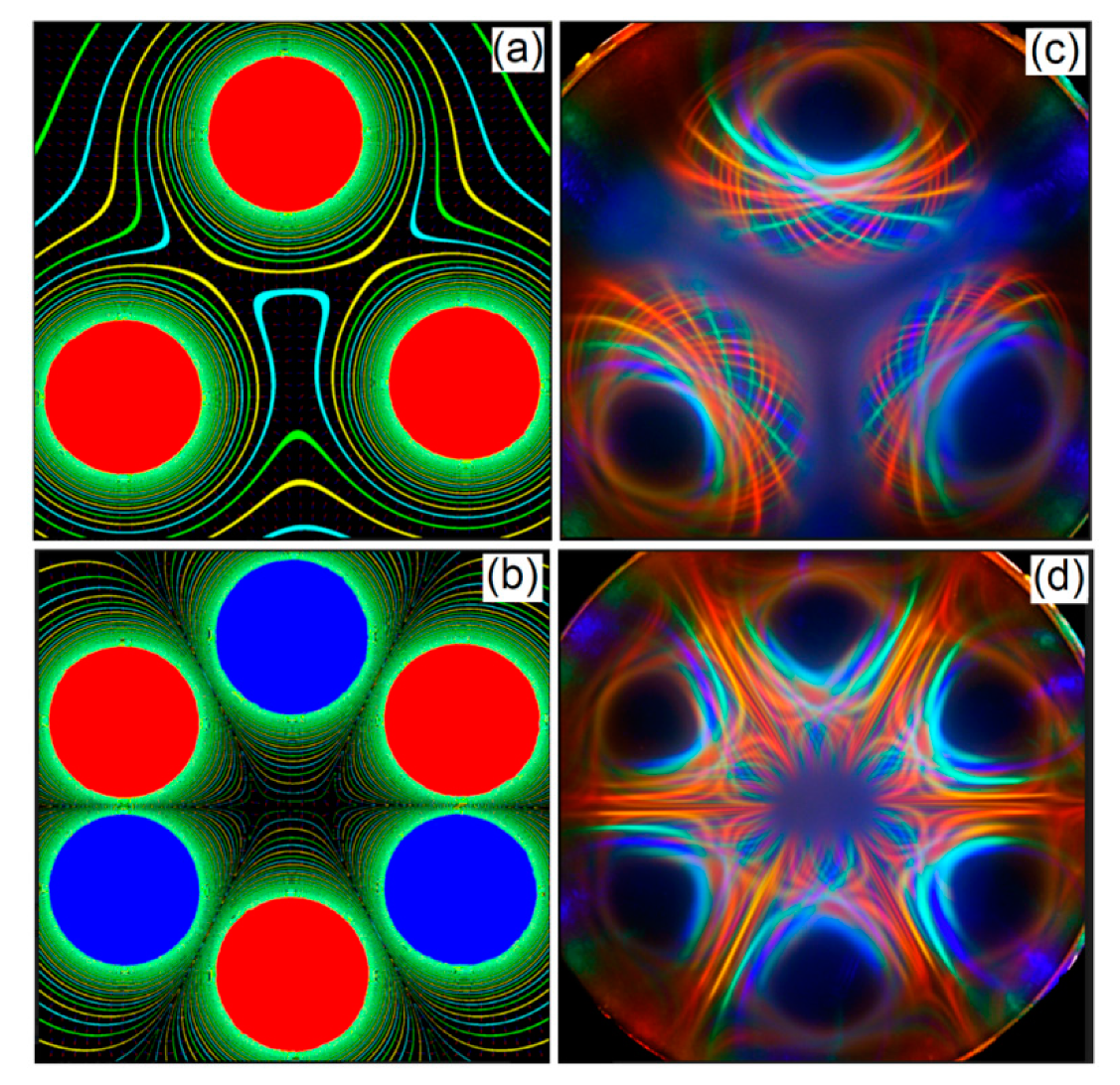
Because this magneto-optical system exhibits a variety of effects, depending on the magnitude of the magnetic field, the magnetic nanoparticles can assemble in very different ways. For example, in
Figure 9, we can see some interesting light patterns for two different magnetic field configurations, using, as the source of light, a ring of LEDs with different colors.
4. Polarization
Another interesting parallel between ferrofluids, clouds and some gems is the patterns obtained using light polarization, because the polarization effects map the orientation of the particles in both a crystal and a complex fluid [
15,
16,
17,
18,
19]. Ferrofluids are liquids where birefringence can be explored by an external magnetic field using a polariscope that examines the sample placed between a pair of polarizers. Placing the thin film of ferrofluid between two crossed polarizers, we can observe some effects of light polarization for different configurations of the magnetic field. For this case, we have used a white light source using an LED panel light (12 W), illuminating over the complete surface of a square of the thin film of ferrofluid (22 × 22 mm) homogeneously, with a methacrylate diffuser using backlighting technique. On the other hand, the conoscopy allows exploring of the light polarization in gems [
17].
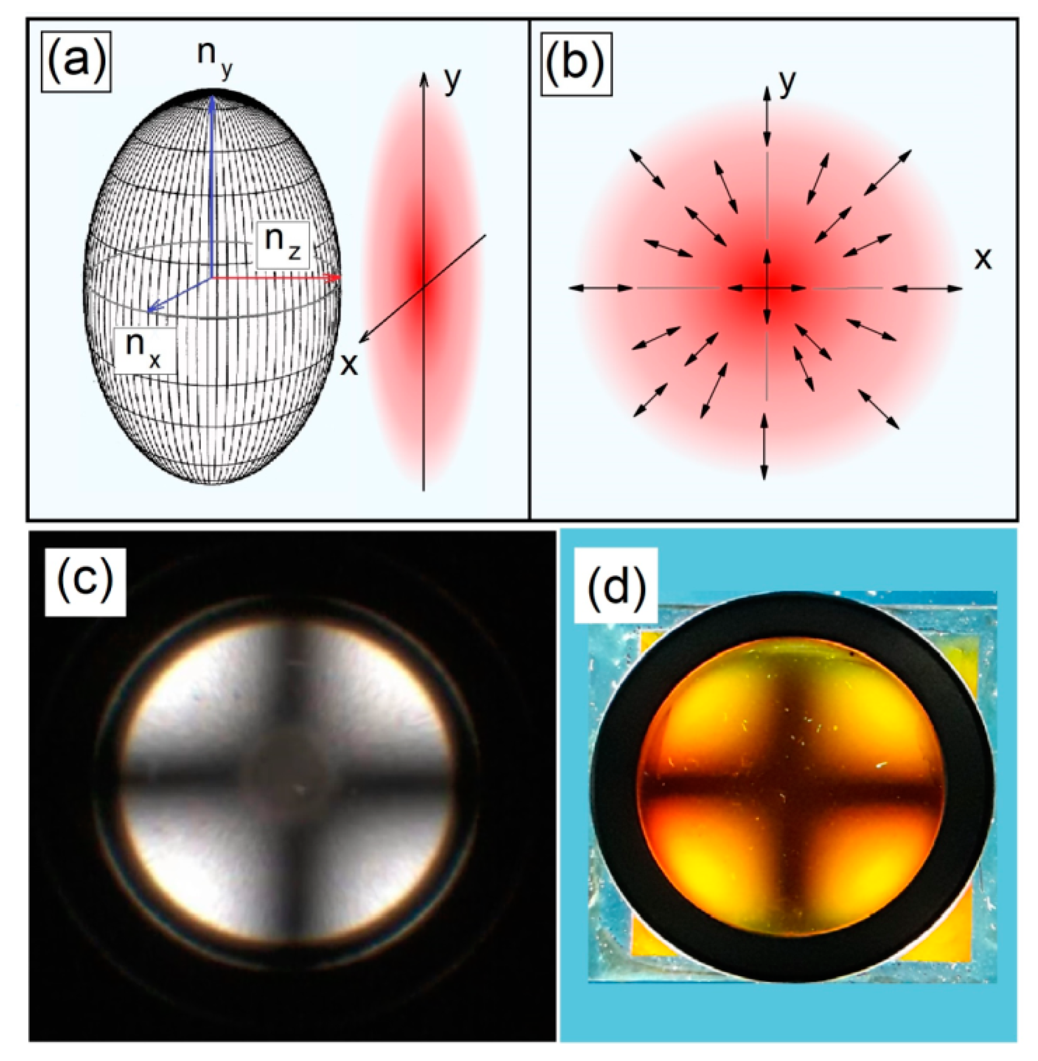
The physical concept connecting both the physical systems is the presence of the birefringence. In the case of the uniaxial crystal, the refractive indices
nx and
ny have the same value, represented in the index ellipsoidal of
Figure 10a, with the polarization modes around the optic axis illustrated in
Figure 10b, while in a biaxial crystal, the three indices are different. In
Figure 10c, we present the comparison between conoscopic pattern in a quartz crystal and the light polarization in the ferrofluid using orthoscopic illumination. The two arms of the cross form the isogyres, while melatope is the point where the isogyres cross each other in the case of gems in
Figure 10c, with a similar pattern obtained in
Figure 10d in the case of the ferrofluid subjected to an axially magnetized ring.
While the ferrofluid system used orthoscopic illumination, with a plane wave, the light pattern obtained with quartz is obtained with conoscopic illumination [
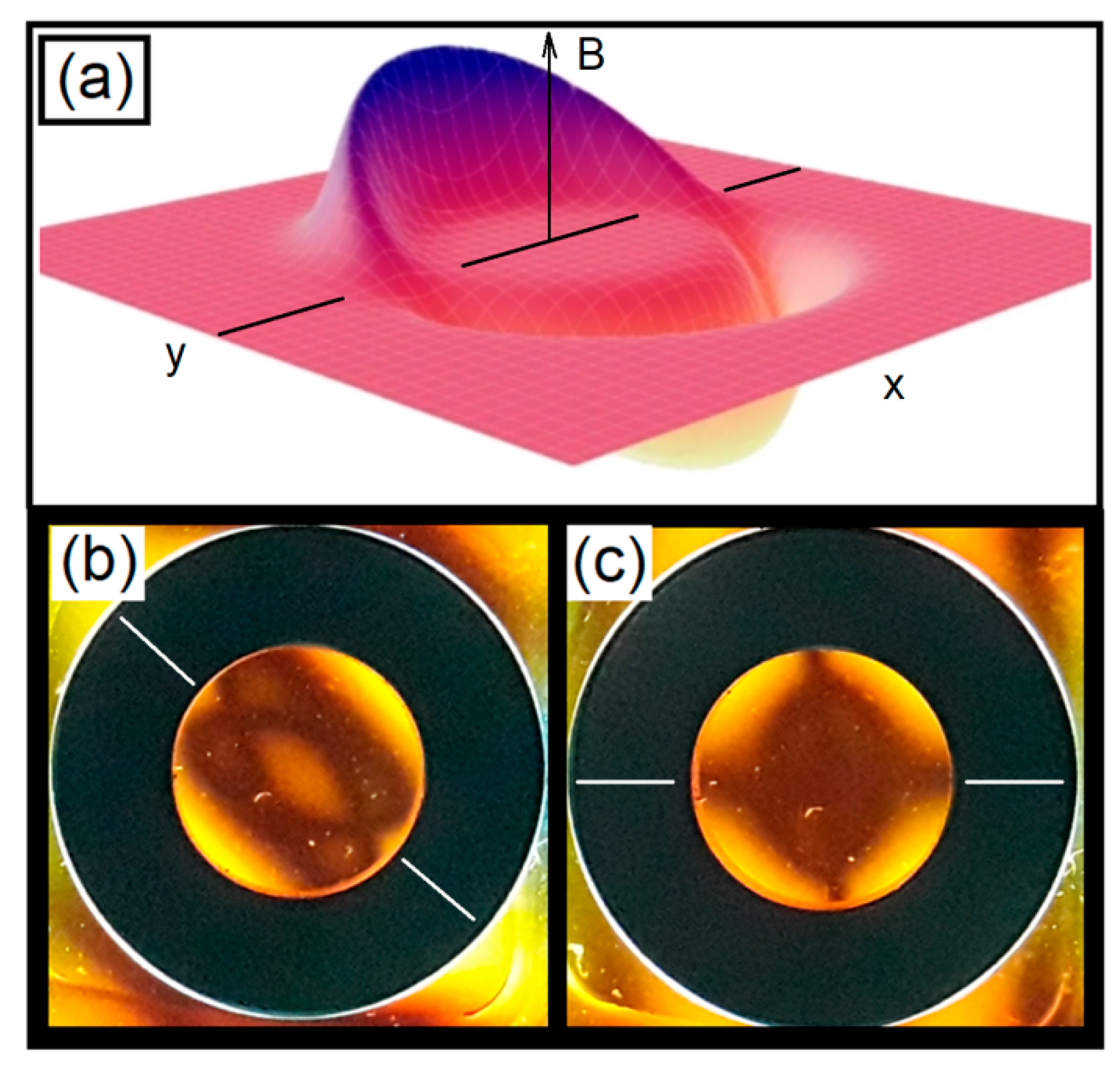
17], represented by a series of concentric light cones. To examine a different magnetic field configuration, we present in
Figure 11a the diagram of the intensity of a magnetic field of the diametrically magnetized ring, and in
Figure 11b,c, the pattern obtained with a Ferrolens.
In
Figure 11, we present the magnetic field intensity diagram of a magnet with diametric magnetization. The light polarization patterns of this magnet ring with the ferrofluid were obtained in
Figure 11b,c; they were obtained by rotating the ring around its axis by an angle of 45 degrees.
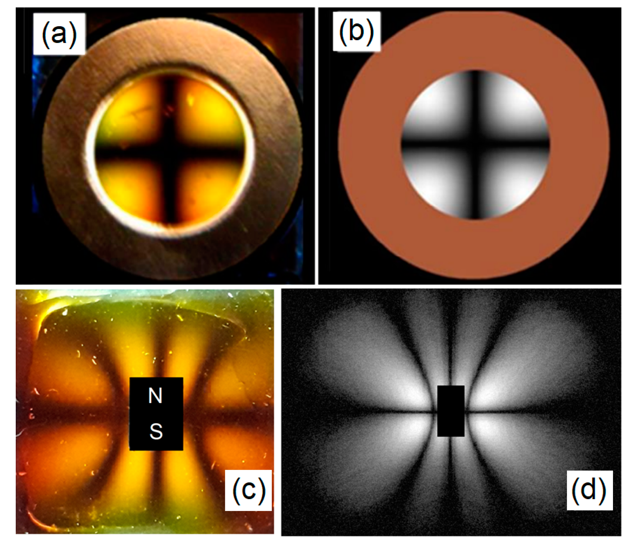
We have obtained a model of the light intensity and the components of the magnetic field in the case of light polarization [
9] given by:
in which,
I(
x,
y,
z) is the light intensity directly observed from the polariscope with the sample of ferrofluid.
B0 is the maximal intensity of the magnetic field,
Hm(
x) and
Hn(
y) are the spatial derivatives of the magnetic field functions in the
x-axis and
y-axis, respectively, in the case of the isogyres-like pattern of
Figure 12a. Using Equation (1), we can obtain the simulation of the light intensity in
Figure 12b for the case presented in
Figure 12a. In
Figure 12c we present the light pattern obtained for the dipolar configuration, with its respective simulation in
Figure 12d.
In this way, the thin film of ferrofluid possesses the ability to rotate the plane of polarization of light passing through them. For more information about optical properties of light scattering in structured fluids, ferrofluids and Ferrocell (Ferrolens), we recommend some references [
20,
21,
22].
5. Conclusions
Stimulated by the report of sundogs and light pillars, we have explored some patterns in ferrofluids and crystals. The main idea involves the existence of certain structures in the atmospheric medium, resembling the patterns observed in some types of gems and ferrofluids, along with some properties of light polarization related to birefringence in ferrofluid and crystals. The light scattering in the ferrofluid is similar to the one observed in a cylindrical rod-like structure along the direction of the propagation, giving rise to the formation of curved light patterns. In the case of jumping sundogs, one possible explanation for this phenomenon is the motion of ice crystals above the clouds controlled by an oscillating electrical field, reflecting the sun light. One important aspect of this work is the versatility of the ferrofluid system, which is used as an analog computer to explore patterns, with the change of some optical parameters of the ferrofluid such as birefringence, ferrofluid concentration, and orientation of the magnetic field.
We have explored some features of the complex fluids of ferrofluids subjected to a magnetic field and compared them to the optical phenomena present in some cases of isogyres observed using conoscopy in gems. One important feature of complex fluids is the presence of polyatomic structures such as polymer molecules or colloidal grains. In the case of the atmospheric optics, the thermodynamics related to the Nakaya diagram controls the shape of the ice crystals floating in the atmosphere, and consequently, enables the existence of light patterns, while in the case of the ferrofluid, the physical properties of the fluid along with the intensity and direction of the magnetic field define the type of light scattering. In order to illustrate what is happening in the light pillars, we have presented some tabletop experiments, which are intended to show concretely the principles discussed, giving a sense of how well the idealizations like chatoyancy can be applied to the atmospheric systems.

 ,
, 


