1. Introduction
Negative capacitance (NC) has become a central topic in modern nanoelectronics, quantum materials, and electromagnetic engineering. Since the seminal theoretical prediction that ferroelectric materials can exhibit an effective negative differential capacitance through polarization dynamics in a double-well potential [
1,
2,
3,
4,
5], NC has been explored as a route to voltage amplification, reduced power consumption in field-effect transistors (NC-FETs), and unconventional electromagnetic responses in metamaterials and plasmonic systems [
2,
3,
4,
5,
6,
7]. Beyond ferroelectrics, NC has also been observed in low-dimensional electron systems with negative compressibility [
8,
9,
10], in nonlinear transport devices [
11,
12,
13], and in resonant tunneling structures [
12,
13,
14]. Despite this diversity, the underlying physical mechanisms remain conceptually fragmented across different research communities.
Existing classifications typically group NC phenomena by material class (ferroelectrics, correlated electron systems, and topological materials [
1,
8,
15]), by device structure (diodes and resonant tunneling devices [
10,
11,
12,
13]), or by electromagnetic response (metamaterials and plasmonic systems [
6,
7,
16]). However, such taxonomies obscure the deeper physical principle that unifies these systems. Recent developments—including our work on tunnel-current-induced NC in nanoscale conductor–semiconductor junctions [
11,
12,
17]—suggest that NC is not an intrinsic property of a specific material but rather a manifestation of non-synchronized or desynchronized responses between an external excitation and the internal dynamics of charge, polarization, or electromagnetic fields [
18,
19,
20].
In this review, we introduce a unified conceptual framework in which NC arises from three fundamental types of non-synchronization:
- -
Temporal mismatch—the response lags behind the excitation, producing a negative phase component in the charge or current [
18,
19,
20].
- -
Spatial mismatch—the spatial distribution of fields or charges does not align with the applied excitation, leading to effective negative permittivity or reactance [
6,
21,
22].
- -
Quantitative mismatch—physical quantities such as permittivity, compressibility, or density of states undergo sign reversal due to resonance or correlation effects [
7,
8,
16].
Within this framework, ferroelectric NC is interpreted as a temporal mismatch in polarization switching [
1,
2,
3], while plasmonic and metamaterial NC arise from spatial or quantitative mismatches in collective electromagnetic modes [
6,
7,
16]. Negative compressibility in two-dimensional electron systems and quantum-capacitance-driven effects naturally fall into the category of quantitative mismatch [
8,
9,
10]. Importantly, our recently proposed tunnel-current-induced NC constitutes a distinct single-particle temporal mismatch mechanism, where the nonlinear and delayed response of electron transport—not polarization—generates the negative capacitive behavior. This mechanism enables the realization of two-dimensional tunable reactance elements (TDTREs), offering a new platform for ultra-compact, high-speed reactive components [
17,
23,
24].
In response to recent developments (2023–2026), we additionally note that NC-related phenomena have also been reported in two-dimensional van der Waals materials, electrochemical systems, and topological or correlated electron systems exhibiting negative quantum capacitance or negative compressibility. These systems naturally fall within the quantitative mismatch category and further broaden the relevance of the unified framework.
By reorganizing the diverse NC phenomena under the unified concepts of synchronization, delay, and mismatch, this review aims to (i) clarify the fundamental physics underlying NC, (ii) highlight the connections between seemingly unrelated systems, and (iii) position tunnel-current-induced NC as a representative mechanism within the broader landscape of NC research [
17,
20,
23,
25]. This unified perspective provides a coherent foundation for understanding NC across disciplines and for designing next-generation reactive elements and electronic devices.
2. Unified Framework for Negative Capacitance: Synchronization, Temporal Delay, and Spatial/Quantitative Mismatch
Negative capacitance (NC) manifests when the response of a physical system—charge, current, polarization, or electromagnetic field—fails to synchronize with an applied excitation. Although NC has been reported in diverse material systems and device architectures, these phenomena can be unified under a single conceptual principle: NC arises from non-synchronization (desynchronization) between excitation and response [
18,
19,
20]. This section introduces a general framework that classifies NC into three fundamental categories based on the nature of this non-synchronization: temporal mismatch, spatial mismatch, and quantitative mismatch [
1,
3,
6,
8,
18,
19,
21,
26]. Together, these categories provide a coherent foundation for interpreting both established and emerging NC mechanisms [
15,
17,
23].
2.1. Synchronization as the Reference State
In conventional capacitive systems, the displacement of charge or polarization is synchronized with the applied voltage. This synchronized state yields a positive capacitance, in which the stored energy increases monotonically with the applied field. Synchronization thus provides the reference state against which all manifestations of NC should be understood. This notion of a synchronized response is consistent with linear-response theory and Kubo’s formulation of irreversible processes [
18,
19,
20].
Mathematically, synchronization implies that the response function
satisfies
, with no phase inversion or sign reversal [
3,
20,
25]. Any deviation from this synchronized behavior—whether in time, space, or magnitude—can generate an effective negative capacitive response.
Here,
denotes a generalized internal response variable of the system, such as charge, polarization, mode amplitude, or any state variable that couples to the applied voltage.
represents the quasi-static (synchronized) response that the system would follow in the absence of delay, inertia, or spatial nonuniformity [
3,
20]. In the synchronized limit, the internal state instantaneously tracks the external excitation, yielding
.
2.2. Temporal Mismatch: Delay Between Excitation and Response
Temporal mismatch occurs when the system’s response lags behind the applied excitation. Such a delay introduces a negative phase component in the current or polarization, which can manifest as NC in small-signal or transient measurements [
18,
19,
20]. This mechanism underlies ferroelectric relaxation, interface trapping, and tunnel-current-induced negative capacitance (TCINC) [
1,
11,
17].
2.2.1. Physical Origin
Temporal mismatch arises from single-particle dynamics or collective relaxation processes, including:
- -
Polarization-switching delay in ferroelectrics, described by Landau–Khalatnikov dynamics [
1,
3].
- -
Charge trapping and detrapping at semiconductor interfaces [
11,
27].
- -
Nonlinear transport delay in diodes and tunneling structures [
11,
12,
13].
- -
Quantum-state occupation delay in resonant tunneling devices [
12,
14].
- -
Spin-relaxation delay in spintronic systems [
28].
- -
Josephson-phase dynamics in superconducting junctions [
29].
These mechanisms demonstrate that temporal mismatch can originate from a wide range of microscopic processes, each producing a delayed response of charge, polarization, or quantum occupation relative to the applied excitation. When this delay becomes sufficiently large, the resulting negative phase component in the AC current or polarization leads to an effective negative capacitance [
18,
19,
20].
2.2.2. Relevance to Tunnel-Current-Induced NC
Our recently proposed tunnel-current-induced NC belongs to this category. In nanoscale conductor–semiconductor junctions, the nonlinear and delayed response of tunneling electrons produces a negative phase component in the AC current, yielding a stable NC without the need for ferroelectric polarization or structural bistability [
11,
12,
17].
2.3. Spatial Mismatch: Nonuniform Field or Charge Distributions
Spatial mismatch refers to situations in which the spatial distribution of electric fields, charges, or polarization does not align with the applied excitation. Such mismatches can produce effective negative permittivity or reactance, particularly in engineered or nanostructured materials [
6,
21,
22].
Physical Origin
Spatial mismatch is characteristic of collective electromagnetic modes, including:
- -
Metamaterials with engineered unit-cell geometries that yield effective negative permittivity or permeability [
6,
22,
30].
- -
Localized plasmonic modes in metallic nanostructures [
7,
31,
32].
- -
Spatially modulated dielectric environments that distort field distributions [
26,
33].
These systems do not rely on temporal delay; instead, the NC-like response emerges from spatially structured collective modes governed by Maxwell’s equations and effective-medium theory [
21,
34].
2.4. Quantitative Mismatch: Sign Reversal of Physical Quantities
Quantitative mismatch occurs when a physical quantity that contributes to capacitance—such as permittivity, compressibility, or density of states—undergoes a sign reversal due to resonance, correlation, or band-structure effects [
8,
10,
35]. This category includes ferroelectric negative curvature, negative electronic compressibility, and resonant permittivity reversal [
1,
7,
16].
Physical Origin
Representative mechanisms include:
- -
Plasmonic negative permittivity, in which the Drude response yields
at frequencies below the plasma frequency [
18,
36].
- -
Negative electronic compressibility in strongly correlated two-dimensional electron systems [
8,
10].
- -
Quantum capacitance sign reversal arising from band-structure anomalies or topological surface states [
9,
37].
- -
Resonant negative permittivity in Lorentz oscillators [
19,
38].
These mechanisms do not require temporal delay; instead, the NC arises from intrinsic material parameters that become negative under specific conditions.
2.5. Summary of the Unified Framework
The three categories—temporal, spatial, and quantitative mismatch—capture the full diversity of NC phenomena reported to date. Importantly, they also clarify the relationships among mechanisms that have historically been treated as unrelated [
2,
6,
8]. This unified framework provides a foundation for interpreting NC across disciplines and for positioning tunnel-current-induced NC as a distinct and fundamental mechanism [
17].
3. Temporal Mismatch: Single-Particle Dynamics Origin
Negative capacitance (NC) arising from temporal mismatch originates from a delay between the applied excitation and the microscopic response of the system. When the response—charge, current, or polarization—fails to follow the excitation synchronously, the resulting phase inversion can produce an effective negative capacitance in the small-signal regime [
18,
19,
20]. This chapter establishes the physical basis of temporal mismatch, reviews known mechanisms, and positions tunnel-current-induced negative capacitance (TCINC) as a distinct single-particle mechanism within this category [
11,
12,
17].
3.1. Conceptual Basis of Temporal Mismatch
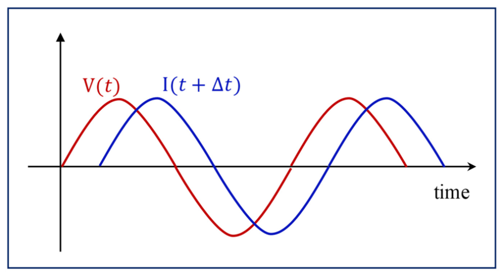
Temporal mismatch refers to a finite delay between the applied voltage and the resulting current . When the delay becomes comparable to the excitation period, the current acquires a negative phase component:
. If
, the imaginary part of the admittance becomes negative, yielding an effective negative capacitance [
18,
19,
20]. A schematic illustration of this basic concept is shown in
Figure 1.
A practical quantitative indicator of temporal mismatch is the condition , under which the phase delay becomes sufficiently large to generate a negative imaginary admittance.
3.2. Ferroelectric Polarization Dynamics (Landau–Khalatnikov Delay)
Ferroelectric negative capacitance was historically interpreted through the Landau–Khalatnikov (L–K) equation, which describes the relaxation of polarization in a double-well potential [
1,
2,
3]. When the applied voltage changes faster than the intrinsic polarization relaxation time, the polarization lags behind the excitation, producing transient negative capacitance.
This mechanism is collective in nature, arising from domain switching, and is fundamentally different from the single-particle mechanisms discussed later.
3.3. Charge Trapping and Interface-State Dynamics
Charge trapping and detrapping at semiconductor interfaces introduce characteristic time constants associated with carrier capture and emission [
9,
11,
27]. When the AC excitation frequency approaches these time constants, the trapped charge cannot follow the excitation, resulting in a delayed response and an effective negative capacitance.
This mechanism is single-particle in origin but is typically parasitic in nature.
3.4. Nonlinear Transport Delay in Diodes and Resonant Tunneling Structures
Nonlinear electronic devices such as pn diodes, Schottky junctions, and resonant tunneling diodes exhibit delayed current responses due to carrier transit times, barrier charging, and quantum-state occupation dynamics. When the excitation frequency approaches this response time, the current acquires a negative phase component, producing an effective negative capacitance [
11,
12,
13].
This mechanism is single-particle in origin and is closely related to the tunnel-current-induced NC discussed in
Section 3.7.
3.5. Tunnel-Current-Induced Negative Capacitance (TCINC): A New Single-Particle Mechanism
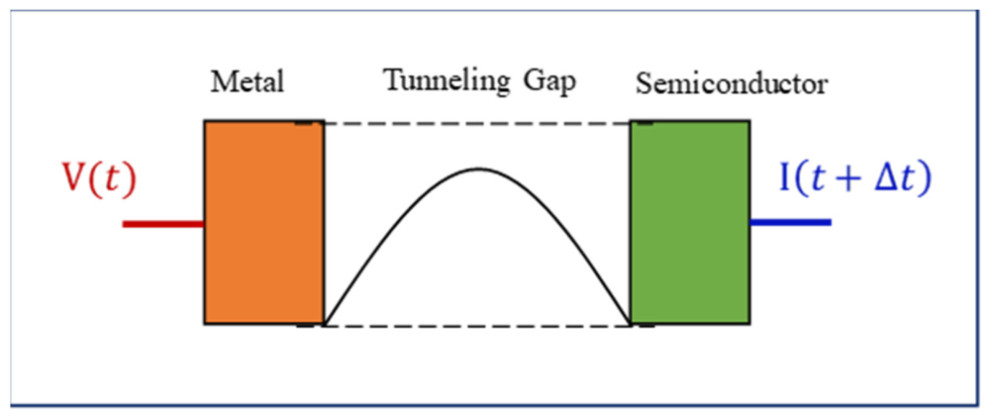
Our recently proposed tunnel-current-induced negative capacitance (TCINC) represents a distinct and previously unclassified mechanism within the temporal mismatch category [
17]. In nanoscale metal–semiconductor junctions, the tunneling current exhibits an intrinsic delay arising from:
- -
Energy-dependent tunneling probability;
- -
The finite response time of carrier injection;
- -
The nonlinear voltage dependence of the tunneling barrier;
- -
Dynamic redistribution of local charge within the nanogap.
Figure 2 provides a simplified illustration of this physical picture.
3.6. Equivalent Circuit Representation of TCINC
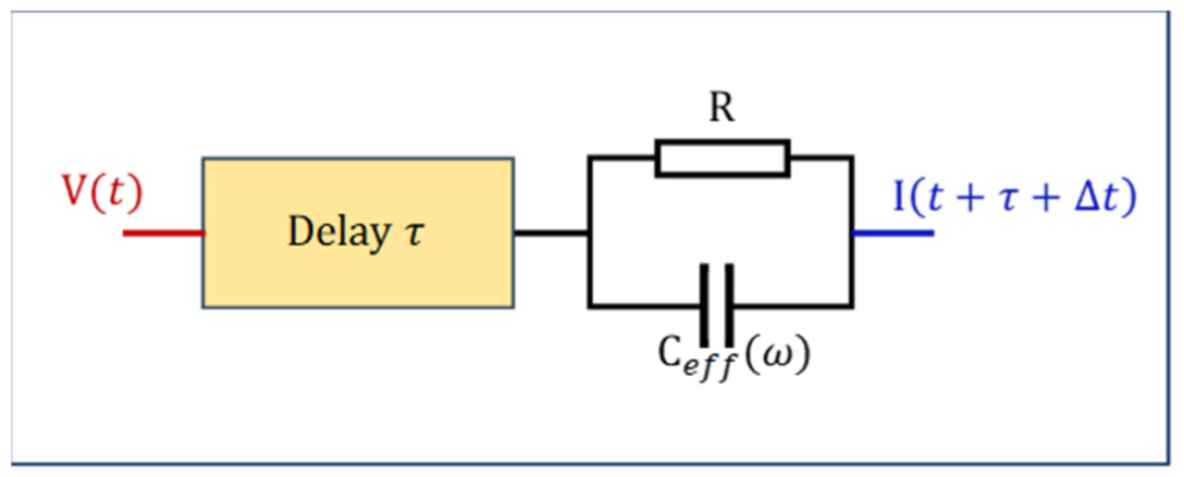
The TCINC mechanism can be captured by a frequency-dependent admittance model, as illustrated in
Figure 3. In this representation, the tunneling junction behaves as a parallel
network, where the effective capacitance is defined by the imaginary part of the admittance:
.
A transport delay element accounts for the finite response time of tunneling electrons. When the delay-induced negative phase component dominates, becomes negative.
This equivalent circuit picture provides a compact and intuitive representation of TCINC, linking the microscopic tunneling delay to a macroscopic negative capacitive response.
3.7. TCINC as a Distinct Category of Temporal Mismatch
As highlighted by the equivalent circuit representation in
Figure 3, TCINC differs fundamentally from previously known mechanisms, as summarized in
Table 1. TCINC clearly stands out as a stable and robust single-particle NC mechanism, filling a conceptual gap in the landscape of negative capacitance research [
12,
13,
17].
Unlike ferroelectric NC—which arises from collective polarization switching—or plasmonic NC—which originates from spatially structured electromagnetic modes, TCINC is rooted in single-particle quantum transport. Its negative capacitance emerges from the intrinsic delay of tunneling electrons responding to a time-varying voltage, without requiring bistability, domain dynamics, or engineered spatial modes.
TCINC is therefore positioned as a representative single-particle mechanism within the temporal mismatch category, complementing other delay-driven NC phenomena without introducing a new category.
4. Spatial Mismatch: Nonuniform Field, Charge, and Mode Distributions
Spatial mismatch refers to situations in which the spatial distribution of electric fields, charges, or polarization does not align with the externally applied excitation. Unlike temporal mismatch—where the response is delayed in time—spatial mismatch arises from geometric, electromagnetic, or modal nonuniformity within the system. Such mismatches can produce effective negative capacitance or negative permittivity even when all underlying material parameters remain positive [
6,
21,
22].
Spatial mismatch mechanisms are fundamentally collective in nature, governed by Maxwell’s equations, boundary conditions, and mode structures rather than by single-particle kinetics [
21,
34]. This chapter outlines the physical origins of spatial mismatch, reviews representative systems, and clarifies how spatially structured electromagnetic modes can generate NC-like responses.
4.1. Conceptual Basis of Spatial Mismatch
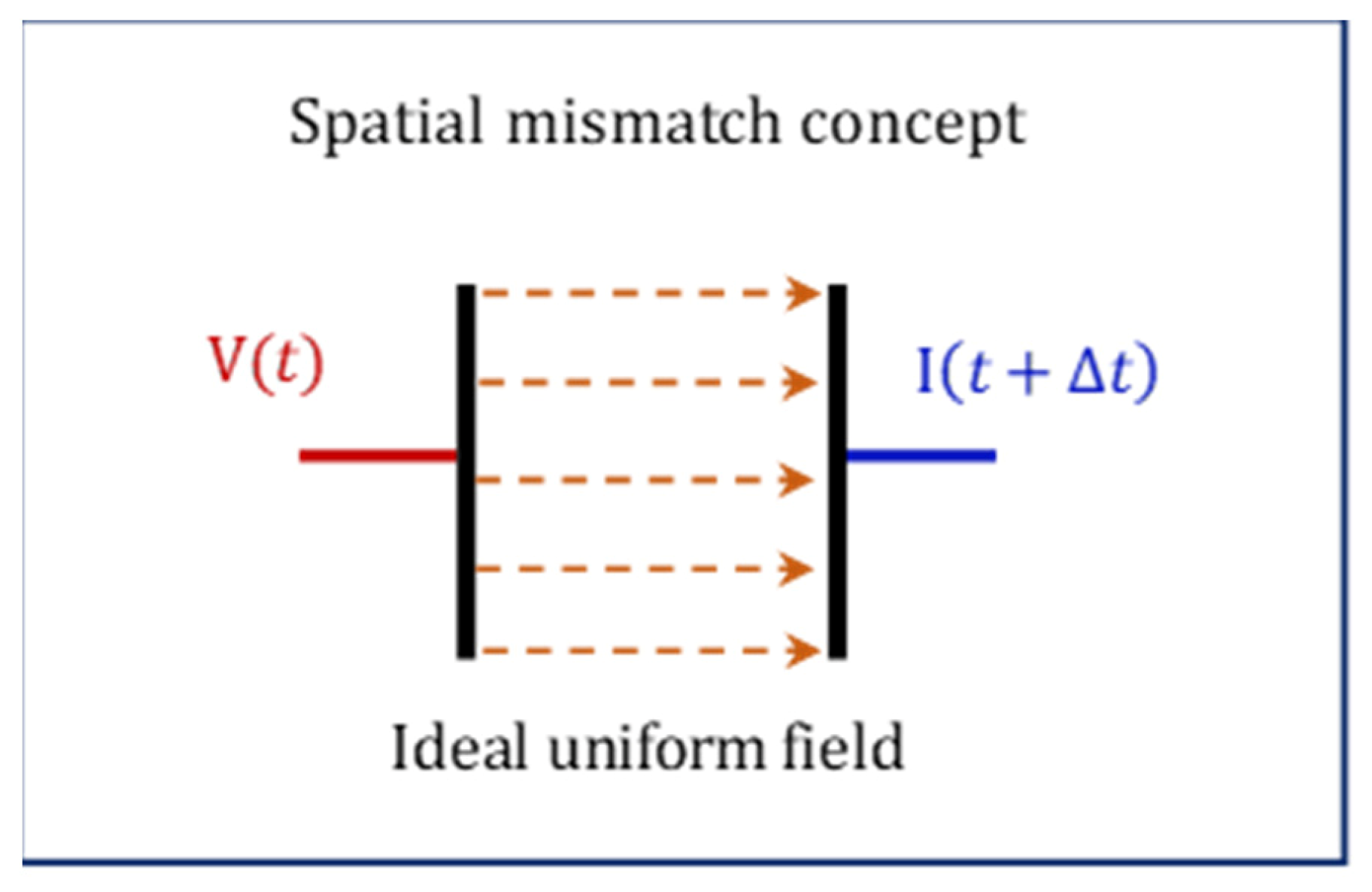
In an ideal parallel-plate capacitor, the electric field is uniform and aligned with the applied voltage. However, in many real or engineered systems, the field distribution becomes nonuniform due to:
- -
Geometric confinement;
- -
Spatially varying permittivity;
- -
Plasmonic or electromagnetic resonances;
- -
Surface or interface modes;
- -
Periodic or metamaterial structures.
When the local field
deviates significantly from the global excitation
, the system can exhibit an effective negative response, such as:
, even though all local material parameters remain positive [
6,
21,
22]. An intuitive illustration of this spatial mismatch is shown in
Figure 4.
Spatial mismatch can be quantitatively identified by nonlocal behavior in the susceptibility , where the response depends explicitly on the spatial wavevector rather than only on frequency.
4.2. Metamaterials and Negative Permittivity
Metamaterials provide the clearest example of spatial mismatch. Their unit-cell geometries—split-ring resonators, fishnet structures, or plasmonic arrays—produce collective electromagnetic modes that can yield:
- -
Negative permittivity ;
- -
Negative permeability ;
- -
Negative index.
These effective parameters do not arise from the intrinsic properties of the constituent materials, which are typically conventional metals and dielectrics. Instead, they emerge from spatially structured resonances that redistribute the electromagnetic field in a highly nonuniform manner [
6,
16,
38].
In particular, the negative permittivity of wire-based metamaterials can be understood as a collective plasma-like response, where the spatial arrangement of metallic elements produces an effective plasma frequency. Below this frequency, effective permittivity becomes negative, even though each individual component has positive permittivity.
This NC-like behavior is therefore a manifestation of mode-induced spatial mismatch, not temporal delay or intrinsic parameter reversal.
4.3. Plasmonic Nanostructures and Localized Field Enhancement
Metallic nanostructures support localized surface-plasmon resonances (LSPRs), in which conduction electrons oscillate collectively. These resonances generate highly nonuniform electromagnetic fields, with extreme localization near sharp tips, edges, or nanogaps.
This spatial concentration of fields can produce:
- -
Negative effective permittivity;
- -
Anomalous charge accumulation;
- -
NC-like impedance signatures.
Unlike TCINC or ferroelectric NC, plasmonic NC arises from collective electron oscillations and geometric confinement, not from temporal delay or intrinsic negative parameters [
7,
31,
32].
The resulting field enhancement and charge redistribution are inherently spatial in origin, making plasmonic systems prototypical examples of spatial mismatch-induced negative responses.
4.4. Spatially Modulated Dielectric Environments
Systems with spatially varying permittivity—such as multilayers, superlattices, or graded-index structures—can exhibit NC-like behavior due to:
- -
Field redistribution across layers;
- -
Interfacial polarization;
- -
Mode hybridization.
Even when each layer has positive permittivity, the effective medium can exhibit negative capacitance because of spatial mismatch between the applied field and the internal field distribution [
21,
26,
33].
These effects arise from collective electromagnetic modes shaped by the geometry and permittivity profile of the structure. The resulting nonuniform field distribution can produce an effective negative response without requiring temporal delay or intrinsic negative parameters.
4.5. Distinction from Temporal Mismatch Mechanisms
Spatial mismatches differ fundamentally from temporal mismatches, as shown in
Table 2.
Spatial mismatch mechanisms are collective and often require engineered geometries, whereas TCINC arises from single-particle quantum transport [
6,
17,
21].
4.6. Positioning Spatial Mismatch in the Unified Framework
Spatial mismatch forms the second pillar of the unified NC framework:
4.6.1. Temporal Mismatch
- -
Delay between excitation and response.
- -
Includes TCINC (single-particle) [
17,
20].
4.6.2. Spatial Mismatch
- -
Nonuniform field or charge distribution.
- -
Includes metamaterials, plasmonics, and multilayers [
6,
7,
21].
4.6.3. Quantitative Mismatch
- -
Sign reversal of intrinsic material parameters.
- -
Includes ferroelectric curvature, negative compressibility, and resonant permittivity [
1,
8,
16].
Spatial mismatch mechanisms demonstrate that NC can arise even in the absence of temporal delay or negative intrinsic parameters. This reinforces the central thesis of this review:
Negative capacitance is fundamentally a manifestation of non-synchronization between excitation and response—whether in time, space, or magnitude.
4.7. Summary of Spatial Mismatch
Spatial mismatch encompasses a broad class of mechanisms in which nonuniform field, charge, or mode distributions give rise to effective negative capacitance or negative permittivity, even when all local material parameters remain positive. Representative examples include metamaterials, plasmonic nanostructures, and spatially modulated dielectric environments, all of which rely on collective electromagnetic modes shaped by geometry and boundary conditions.
These mechanisms highlight that NC does not require temporal delay or intrinsic negative parameters. Instead, spatially structured field distributions alone can produce NC-like responses, positioning spatial mismatch as a distinct and essential pillar of the unified NC framework.
5. Quantitative Mismatch
Quantitative mismatch refers to situations in which the magnitude or sign of an intrinsic material parameter—such as permittivity, susceptibility, or compressibility—differs from the externally imposed excitation in such a way that the effective response becomes negative. Unlike temporal mismatch, which arises from delayed dynamics, and spatial mismatch, which originates from nonuniform field distributions, quantitative mismatch is rooted in the intrinsic constitutive relations of the material itself [
1,
7,
8].
This category includes systems in which effective permittivity, capacitance, or susceptibility becomes negative due to:
- -
Phase transitions;
- -
Internal free-energy curvature;
- -
Electronic or ionic instabilities;
- -
Collective oscillations;
- -
Engineered resonances.
Quantitative mismatch is therefore the most “material-centric” of the three categories.
5.1. Conceptual Basis
In a linear dielectric, the constitutive relation is , with .
However, in systems with internal instabilities or resonances, effective permittivity can become negative: .
This sign reversal implies that the induced polarization opposes the applied field more strongly than in a normal dielectric, leading to an effective negative capacitance: .
The key point is that the negative response originates from the intrinsic free-energy landscape or resonance structure, not from delays (temporal mismatch) nor from field nonuniformity (spatial mismatch) [
1,
16,
19].
5.2. Ferroelectric Curvature
The most widely discussed example of quantitative mismatch is the ferroelectric negative capacitance predicted by Landau theory [
1,
2,
3].
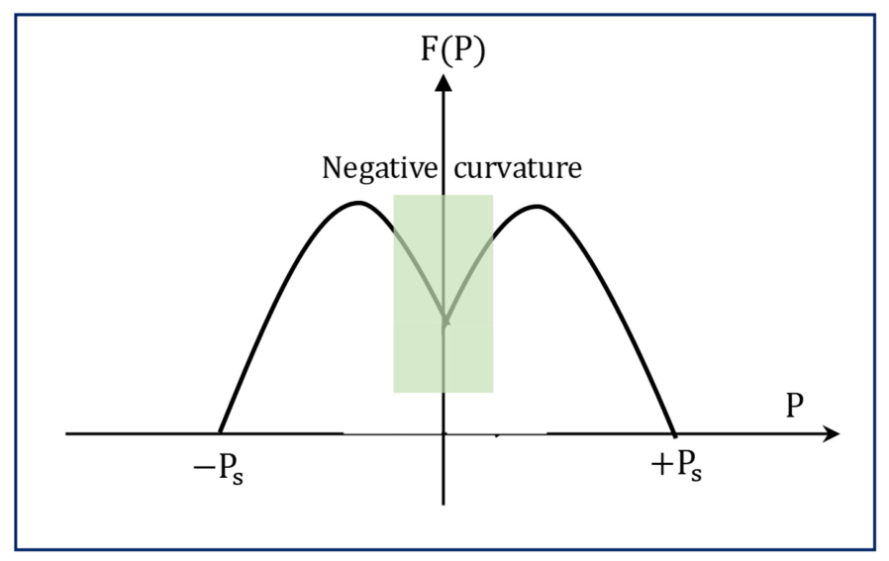
In a ferroelectric, the free energy has a double-well structure: , where the curvature can become negative in the region between the wells.
This negative curvature region is the source of the negative capacitance arising from the quantitative mismatch. A conceptual diagram is shown in
Figure 5.
5.3. Negative Compressibility
In low-dimensional electron systems (2DEGs, graphene, oxide interfaces), electron–electron interactions can produce negative electronic compressibility [
6,
7,
8]:
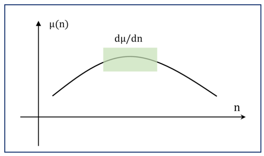
. This leads to counterintuitive behavior such as:
- -
Capacitance exceeding the geometric limit;
- -
Effective negative capacitance in quantum capacitance measurements;
- -
Enhanced charge accumulation.
Figure 6 illustrates the essential physics: the chemical potential decreases with increasing carrier density.
5.4. Ionic and Electrochemical Negative Capacitance
Electrochemical interfaces can exhibit negative differential capacitance due to:
- -
Ion crowding;
- -
Overscreening;
- -
Charge inversion;
- -
Non-monotonic chemical potential.
In these systems, the internal chemical potential gradient has the opposite sign to the external electric field, resulting in a negative capacitance arising from a quantitative mismatch [
10,
35,
37].
5.5. Resonant Systems
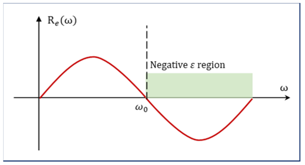
Resonant systems—such as Lorentz oscillators—can exhibit negative effective permittivity in frequency ranges above resonance [
16,
19,
38]:
, where
denotes the oscillator strength, representing the coupling strength between the external electric field and the bound charge. It determines the amplitude of the resonant contribution to the dielectric response. Also, the parameter (
) represents the damping constant, describing the energy dissipation rate of the bound oscillator. It determines the linewidth of the resonance and accounts for scattering or relaxation processes. When
, the real part of
can become negative. This sign reversal due to resonance is shown in
Figure 7.
5.6. Distinction
Quantitative mismatch differs fundamentally from the other two categories, as shown in
Table 3.
It is the only category in which the material itself possesses a negative intrinsic response.
5.7. Positioning
Quantitative mismatch forms the third pillar of the unified NC framework:
5.7.1. Spatial Mismatch
- -
Nonuniform field or charge distribution.
- -
Includes metamaterials and plasmonics [
6,
7,
21].
5.7.2. Quantitative Mismatch
- -
Intrinsic parameter reversal.
- -
Includes ferroelectric free-energy curvature, negative compressibility, and resonant negative permittivity [
1,
8,
16].
Together, these three categories demonstrate that negative capacitance is not a single phenomenon, but a broad class of behaviors unified by the principle of non-synchronization between excitation and response.
6. Unified Perspective and Design Implications
Negative capacitance (NC) has historically been discussed within disparate scientific communities—ferroelectrics, quantum transport, plasmonics, metamaterials, and electrochemistry—each using its own terminology and conceptual framework. The preceding chapters have shown that these diverse manifestations can be systematically organized into three fundamental categories:
Temporal mismatch [
17,
20].
Spatial mismatch (Chapter 4) [
6,
21].
Quantitative mismatch (Chapter 5) [
1,
8,
16].
Despite their apparent differences, these mechanisms share a common underlying principle: negative capacitance emerges whenever the internal response of a system becomes non-synchronized with the external excitation, regardless of whether the mismatch is temporal, spatial, or quantitative [
18,
19,
20].
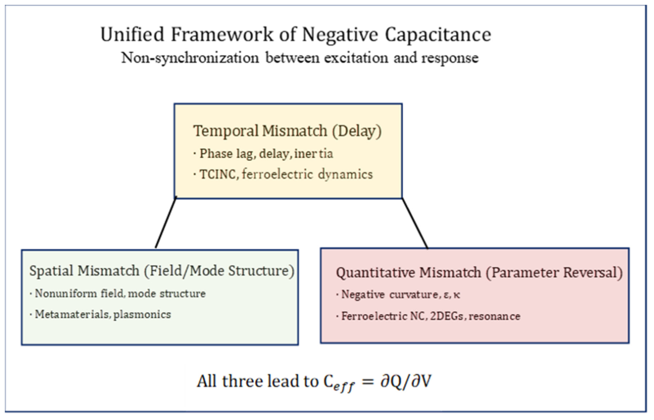
To visualize this unified perspective,
Figure 8 summarizes the three categories and their relationships.
6.1. Unified View: Negative Capacitance as Non-Synchronization
The three categories can be mapped onto a single conceptual axis: the degree and nature of non-synchronization between excitation and response, as shown in
Table 4.
This unified view clarifies that NC is not a single phenomenon, but a family of responses governed by the same mathematical structure: .
Negative capacitance arises whenever the internal variable (charge, polarization, chemical potential, or mode amplitude) responds in a manner that opposes or overshoots the external driving [
18,
19,
20].
6.2. Implications for Device Design
6.2.1. Ferroelectric NC for Steep-Slope Transistors
The unified framework highlights two distinct routes to NC in ferroelectrics:
- -
Dynamic NC (temporal mismatch) [
1,
20].
- -
Static NC (quantitative mismatch) [
1,
2,
3].
This distinction is crucial for transistor design:
- -
Dynamic NC is frequency-dependent and may vanish under DC operation.
- -
Static NC is stable but requires careful stabilization through series capacitors.
Designers must therefore identify which regime their device operates in and avoid conflating the two.
6.2.2. Tunneling-Based NC for High-Frequency Applications
TCINC (Chapter 3) is a single-particle, delay-driven NC mechanism that naturally operates at high frequencies.
The unified framework clarifies that:
- -
TCINC is fundamentally different from ferroelectric NC [
12,
17];
- -
TCINC does not require negative free-energy curvature [
11,
17];
- -
TCINC can be engineered via barrier shape, thickness, and density of states.
This opens pathways for RF/THz NC devices based on quantum transport rather than ferroelectricity.
6.2.3. Metamaterial NC for Wave Manipulation
Spatial mismatch mechanisms (Chapter 4) enable:
- -
Negative permittivity;
- -
Negative index;
- -
Sub-wavelength focusing;
- -
Field enhancement.
These effects are inherently collective and geometric, suggesting that NC can be engineered without exotic materials—solely through structural design [
6,
7,
21].
6.3. Implications for Materials Design
6.3.1. Engineering Free-Energy Landscapes
Quantitative mismatch mechanisms (Chapter 5) show that NC can be tuned through:
- -
Composition;
- -
Strain;
- -
Dimensionality;
- -
Interface engineering.
For example:
- -
Strain can deepen or flatten ferroelectric wells [
1];
- -
Two-dimensional materials can enhance electronic correlations [
8];
- -
Superlattices can tailor permittivity profiles [
21].
This suggests a materials-by-design approach to NC.
6.3.2. Controlling Spatial Mode Structure
Spatial mismatch NC depends on:
- -
Geometry;
- -
Boundary conditions;
- -
Mode hybridization.
Thus, NC can be engineered through:
- -
Nanopatterning;
- -
Plasmonic resonators;
- -
Multilayer stacks;
- -
Photonic crystals [
6,
7,
21].
This provides a route to NC without relying on intrinsic material instabilities.
6.4. Implications for Measurement and Interpretation
The unified framework helps avoid several common misinterpretations:
6.4.1. NC Does Not Imply Ferroelectricity
Temporal mismatch mechanisms (e.g., TCINC) and spatial mismatch mechanisms (e.g., plasmonics) can both produce NC without any ferroelectric behavior [
6,
7,
17]. In addition, a negative capacitance effect has been observed at the interface between Si wafers with undulating surfaces [
24].
6.4.2. NC Does Not Require Hysteresis
Only some quantitative mismatch systems exhibit hysteresis. Temporal mismatch NC can be entirely hysteresis-free [
17,
20].
6.4.3. Frequency Dependence Reveals the Mechanism
- -
Temporal mismatch → strong frequency dispersion [
18,
20];
- -
Spatial mismatch → modal resonances [
6,
21];
- -
Quantitative mismatch → intrinsic sign reversal [
1,
8,
16].
Thus, frequency-domain measurements can distinguish among the mechanisms.
6.5. Design Guidelines Derived from the Unified Framework
6.5.1. Identify the Mismatch Type
- -
Time, space, or magnitude?
- -
This determines stability and frequency response.
6.5.2. Match the NC Mechanism to the Application
- -
High-frequency → TCINC [
17];
- -
Wave manipulation → spatial mismatch [
6,
21];
- -
Steep-slope logic → quantitative mismatch [
1,
8].
6.5.3. Avoid Conflating Dynamic and Static NC
- -
Especially in ferroelectric devices.
6.5.4. Use Geometry as a Design Parameter
- -
Spatial mismatch mechanisms enable NC without exotic materials.
6.5.5. Use Free-Energy Engineering for Stable NC
- -
Interfaces, strain, and dimensionality are key.
6.6. Outlook: Toward a General Theory of Negative Response
The unified framework suggests that NC is part of a broader class of negative-response phenomena, including:
- -
Negative differential resistance;
- -
Negative compressibility;
- -
Negative permeability;
- -
Negative index.
All of these arise from non-synchronization between internal and external variables [
18,
19,
20].
A general theory of negative response would unify these phenomena under a single mathematical and physical framework, enabling systematic design of devices with tailored negative properties.
7. Conclusions
Negative capacitance (NC) has been reported across a wide range of physical systems, yet its interpretation has remained fragmented due to the absence of a unified conceptual framework. Existing explanations—spanning ferroelectric free-energy curvature, tunneling transport, plasmonic resonances, and electronic compressibility—have often been treated as unrelated or even contradictory. This review resolves these inconsistencies by showing that all manifestations of NC arise from non-synchronization between external excitation and internal responses.
We classified NC into three fundamental categories:
Temporal mismatch—arising from delays or inertia in charge, polarization, or quantum-state dynamics.
Spatial mismatch—originating from nonuniform field or mode distributions.
Quantitative mismatch—resulting from intrinsic parameter reversal, such as negative curvature, negative compressibility, or resonant permittivity.
Despite their diverse physical origins, these mechanisms share the same mathematical signature (). Organizing NC within this unified framework clarifies long-standing ambiguities, connects previously isolated research fields, and establishes a systematic foundation for engineering NC in electronic, photonic, and quantum devices.
The framework further highlights tunnel-current-induced NC as a representative single-particle mechanism, expanding the scope of NC beyond ferroelectricity and collective modes. At the same time, it situates TCINC within the broader category of temporal mismatch, maintaining conceptual consistency with other NC mechanisms.
Overall, this work positions NC not as a singular anomaly but as a universal response class emerging from the interplay between excitation and internal dynamics. By identifying the structural origins of NC in the response function, the unified framework offers a coherent and versatile perspective that can guide future research in materials science, device engineering, and electromagnetic theory. These results reinforce that all manifestations of negative capacitance can be coherently understood within the unified framework of temporal, spatial, and quantitative mismatch.
Author Contributions
Conceptualization, Y.S.; methodology, S.K.; software, Y.S. and S.K.; validation, Y.S. and S.K.; formal analysis, Y.S. and S.K.; investigation, Y.S.; resources, Y.S.; data curation, Y.S.; writing—original draft preparation, Y.S. and S.K.; writing—review and editing, Y.S. and S.K.; visualization, Y.S.; supervision, Y.S.; project administration, Y.S.; funding acquisition, Y.S. All authors have read and agreed to the published version of the manuscript.
Funding
This work was partially supported by the Takahashi Industrial and Economic Research Foundation (Grant No. 12-003-101) and by the Japan Society for the Promotion of Science (JSPS) through a Grant-in-Aid for Scientific Research (C) (Grant No. 23K03868).
Data Availability Statement
Data are contained within the article.
Conflicts of Interest
The authors declare no conflicts of interest.
References
- Landau, L.D.; Khalatnikov, I.M. On the anomalous absorption of sound near a second order phase transition point. Zh. Eksp. Teor. Fiz. 1954, 27, 431–438. [Google Scholar]
- Salahuddin, S.; Datta, S. Use of Negative Capacitance to Provide Voltage Amplification for Low Power Nanoscale Devices. Nano Lett. 2008, 8, 405–410. [Google Scholar] [CrossRef] [Scilit]
- Dawber, M.; Rabe, K.M.; Scott, J.F. Physics of Thin-Film Ferroelectric Oxides. Rev. Mod. Phys. 2005, 77, 1083–1130. [Google Scholar] [CrossRef] [Scilit]
- Cheema, S.S.; Shanker, N.; Hsu, S.-L.; Schaadt, J.; Ellis, N.M.; Cook, M.; Rastogi, R.; Pilawa-Podgurski, R.C.N.; Ciston, J.; Mohamed, M.; et al. Giant Energy Storage and Power Density Negative Capacitance Superlattices. Nature 2024, 629, 803–809. [Google Scholar] [CrossRef] [Scilit]
- Zhirnov, V.V.; Cavin, R.K. Negative Capacitance to the Rescue? Nat. Nanotechnol. 2008, 3, 77–78. [Google Scholar] [CrossRef] [Scilit]
- Smith, D.R.; Pendry, J.B.; Wiltshire, M.C.K. Metamaterials and Negative Refractive Index. Science 2004, 305, 788–792. [Google Scholar] [CrossRef] [Scilit] [PubMed]
- Maier, S.A. Plasmonics: Fundamentals and Applications; Springer: New York, NY, USA, 2007; Available online: https://link.springer.com/book/10.1007/0-387-37825-1 (accessed on 14 April 2026).
- Eisenstein, J.P.; Pfeiffer, L.N.; West, K.W. Negative compressibility of interacting two-dimensional electron and quasiparticle gases. Phys. Rev. Lett. 1992, 68, 674–677. [Google Scholar] [CrossRef] [Scilit]
- Luryi, S. Quantum Capacitance Devices. Appl. Phys. Lett. 1988, 52, 501–503. [Google Scholar] [CrossRef] [Scilit]
- Bazant, M.Z.; Storey, B.D.; Kornyshev, A.A. Double Layer in Ionic Liquids: Overscreening versus Crowding. Phys. Rev. Lett. 2011, 106, 046102. [Google Scholar] [CrossRef] [Scilit]
- Sze, S.M.; Ng, K.K. Physics of Semiconductor Devices, 3rd ed.; Wiley: Hoboken, NJ, USA, 2006; Available online: https://wiley.co.jp/books/chem_phys/physics_semiconductor_devic.html (accessed on 14 April 2026).
- Tsu, R.; Esaki, L. Tunneling in a Finite Superlattice. Appl. Phys. Lett. 1973, 22, 562–564. [Google Scholar] [CrossRef] [Scilit]
- Esaki, L. New Phenomenon in Narrow Germanium p–n Junctions. Phys. Rev. 1958, 109, 603–604. [Google Scholar] [CrossRef] [Scilit]
- Landau, L.D.; Lifshitz, E.M. Electrodynamics of Continuous Media; Pergamon Press: Oxford, UK, 1960. [Google Scholar]
- Hasan, M.Z.; Kane, C.L. Colloquium: Topological Insulators. Rev. Mod. Phys. 2010, 82, 3045–3067. [Google Scholar] [CrossRef] [Scilit]
- Pendry, J.B. Negative Refraction Makes a Perfect Lens. Phys. Rev. Lett. 2000, 85, 3966–3969. [Google Scholar] [CrossRef] [Scilit]
- Sun, Y.; Kanemitsu, S. Two-Dimensional Tunable Reactance Element Free from Electromagnetic Coupling. Condens. Matter 2026, 11, 9. [Google Scholar] [CrossRef] [Scilit]
- Drude, P. Zur Elektronentheorie der Metalle. Ann. Phys. 1900, 306, 566–613. [Google Scholar] [CrossRef] [Scilit]
- Lorentz, H.A. The Theory of Electrons; Teubner: Leipzig, Germany, 1909; Available online: https://archive.org/details/cu31924005244615 (accessed on 14 April 2026).
- Kubo, R. Statistical-Mechanical Theory of Irreversible Processes. J. Phys. Soc. Jpn. 1957, 12, 570–586. [Google Scholar] [CrossRef] [Scilit]
- Joannopoulos, J.D.; Johnson, S.G.; Winn, J.N.; Meade, R.D. Photonic Crystals; Princeton University Press: Princeton, NJ, USA, 2008. [Google Scholar]
- Smith, D.R.; Schultz, S.; Markoš, P.; Soukoulis, C.M. Determination of Effective Permittivity and Permeability of Metamaterials from reflection and transmission coefficients. Phys. Rev. B 2002, 65, 195104. [Google Scholar] [CrossRef] [Scilit]
- Sun, Y.; Yasunaga, H.; Shiraishi, M.; Sakai, H. Volatile capacitance of resistor with differential resistance. Appl. Phys. Lett. 2024, 125, 143501. [Google Scholar] [CrossRef] [Scilit]
- Yasunaga, H.; Yano, K.; Tanioka, Y.; Fujimoto, S.; Kanemitsu, S.; Sun, Y. Negative capacitance effect at interface between Si wafers with undulating surfaces. Crystals 2025, 15, 798. [Google Scholar] [CrossRef] [Scilit]
- Stratton, J.A. Electromagnetic Theory; McGraw–Hill: New York, NY, USA, 1941. [Google Scholar]
- Martin, J.; Akerman, N.; Ulbricht, G.; Lohmann, T.; Klitzing, K.V.; Smet, J.H.; Yacoby, A. The nature of localization in graphene under quantum Hall conditions. Nat. Phys. 2009, 5, 669–674. [Google Scholar] [CrossRef] [Scilit]
- Nicollian, E.H.; Brews, J.R. MOS (Metal Oxide Semiconductor) Physics and Technology; Wiley: New York, NY, USA, 2002. [Google Scholar]
- Žutić, I.; Fabian, J.; Das Sarma, S. Spintronics: Fundamentals and Applications. Rev. Mod. Phys. 2004, 76, 323–410. [Google Scholar] [CrossRef] [Scilit]
- Josephson, B.D. Possible New Effects in Superconductive Tunnelling. Phys. Lett. 1962, 1, 251–253. [Google Scholar] [CrossRef] [Scilit]
- Khan, A.I.; Chatterjee, K.; Wang, B.; Drapcho, S.; You, L.; Serrao, C.; Bakaul, S.R.; Ramesh, R.; Salahuddin, S. Negative Capacitance in a Ferroelectric Capacitor. Nat. Mater. 2015, 14, 182–186. [Google Scholar] [CrossRef] [Scilit]
- Shelby, R.A.; Smith, D.R.; Schultz, S. Experimental Verification of a Negative Index of Refraction. Science 2001, 292, 77–79. [Google Scholar] [CrossRef] [Scilit]
- Engheta, N. Circuits with Light at Nanoscales. Science 2007, 317, 1698–1702. [Google Scholar] [CrossRef] [Scilit]
- Zwanzig, R. Nonequilibrium Statistical Mechanics; Oxford University Press: Oxford, UK, 2001; Available online: https://academic.oup.com/book/52730 (accessed on 14 April 2026).
- Harrison, W.A. Tunneling from an Independent-Particle Point of View. Phys. Rev. 1961, 123, 85–89. [Google Scholar] [CrossRef] [Scilit]
- Kornyshev, A.A. Double-Layer in Ionic Liquids: Paradigm Change? J. Phys. Chem. B 2007, 111, 5545–5557. [Google Scholar] [CrossRef] [Scilit] [PubMed]
- Krupka, J. Materials with Negative Permittivity or Negative Permeability—Review, Electrodynamic Modelling, and Applications. Materials 2025, 18, 423. [Google Scholar] [CrossRef] [Scilit]
- Qi, X.L.; Zhang, S.C. Topological Insulators and Superconductors. Rev. Mod. Phys. 2011, 83, 1057–1110. [Google Scholar] [CrossRef] [Scilit]
- Pendry, J.B.; Smith, D.R. Reversing Light With Negative Refraction. Phys. Today 2004, 57, 37–43. [Google Scholar] [CrossRef] [Scilit]
Figure 1.
Temporal mismatch between the applied voltage and the tunneling current. A finite response delay causes the tunneling current to lag the excitation , introducing a negative phase component. When this phase lag becomes sufficiently large, the imaginary part of the admittance becomes negative, resulting in an effective negative capacitance in the small-signal regime.
Figure 1.
Temporal mismatch between the applied voltage and the tunneling current. A finite response delay causes the tunneling current to lag the excitation , introducing a negative phase component. When this phase lag becomes sufficiently large, the imaginary part of the admittance becomes negative, resulting in an effective negative capacitance in the small-signal regime.
Figure 2.
Schematic illustration of the tunnel-current-induced negative capacitance (TCINC) mechanism. An AC excitation modulates the tunneling barrier in a nanoscale metal–semiconductor junction. Because the tunneling current responds with a finite delay determined by the energy-dependent tunneling probability and carrier injection dynamics, the current acquires a negative phase component, giving rise to a stable negative capacitance.
Figure 2.
Schematic illustration of the tunnel-current-induced negative capacitance (TCINC) mechanism. An AC excitation modulates the tunneling barrier in a nanoscale metal–semiconductor junction. Because the tunneling current responds with a finite delay determined by the energy-dependent tunneling probability and carrier injection dynamics, the current acquires a negative phase component, giving rise to a stable negative capacitance.
Figure 3.
Equivalent-circuit representation of TCINC. The tunneling junction is modeled as a parallel network combined with a transport-delay element. When the delay-induced negative phase dominates over the capacitive response, the extracted effective capacitance becomes negative.
Figure 3.
Equivalent-circuit representation of TCINC. The tunneling junction is modeled as a parallel network combined with a transport-delay element. When the delay-induced negative phase dominates over the capacitive response, the extracted effective capacitance becomes negative.
Figure 4.
Conceptual illustration of spatial mismatch. In an ideal capacitor, the electric field is uniform and aligned with the applied voltage. In real or engineered structures—such as plasmonic nanostructures, metamaterials, or systems with geometric confinement—the local electric field becomes highly nonuniform. Strong field localization near tips, edges, or interfaces redistributes charge spatially, producing an effective negative capacitive response even when all intrinsic material parameters remain positive.
Figure 4.
Conceptual illustration of spatial mismatch. In an ideal capacitor, the electric field is uniform and aligned with the applied voltage. In real or engineered structures—such as plasmonic nanostructures, metamaterials, or systems with geometric confinement—the local electric field becomes highly nonuniform. Strong field localization near tips, edges, or interfaces redistributes charge spatially, producing an effective negative capacitive response even when all intrinsic material parameters remain positive.
Figure 5.
Free-energy landscape of a ferroelectric material. The region between the two polarization minima exhibits negative curvature , corresponding to a negative differential permittivity and thus negative capacitance.
Figure 5.
Free-energy landscape of a ferroelectric material. The region between the two polarization minima exhibits negative curvature , corresponding to a negative differential permittivity and thus negative capacitance.
Figure 6.
Electronic compressibility in a strongly interacting electron system. When the chemical potential decreases with increasing carrier density , the electronic compressibility becomes negative, leading to effective negative capacitance in quantum-capacitance measurements.
Figure 6.
Electronic compressibility in a strongly interacting electron system. When the chemical potential decreases with increasing carrier density , the electronic compressibility becomes negative, leading to effective negative capacitance in quantum-capacitance measurements.
Figure 7.
Lorentz oscillator model showing the frequency dependence of the real part of the permittivity. Above the resonance frequency , the real part of becomes negative due to the phase reversal of the bound electron response, producing a negative permittivity regime.
Figure 7.
Lorentz oscillator model showing the frequency dependence of the real part of the permittivity. Above the resonance frequency , the real part of becomes negative due to the phase reversal of the bound electron response, producing a negative permittivity regime.
Figure 8.
Unified map of the three fundamental mechanisms of negative capacitance. Temporal mismatch arises from delays or inertia in the internal response; spatial mismatch originates from nonuniform field or mode distributions; quantitative mismatch results from intrinsic parameter reversal, such as negative curvature or negative compressibility. All three mechanisms represent distinct manifestations of non-synchronization between excitation and response, leading to an effective negative capacitance .
Figure 8.
Unified map of the three fundamental mechanisms of negative capacitance. Temporal mismatch arises from delays or inertia in the internal response; spatial mismatch originates from nonuniform field or mode distributions; quantitative mismatch results from intrinsic parameter reversal, such as negative curvature or negative compressibility. All three mechanisms represent distinct manifestations of non-synchronization between excitation and response, leading to an effective negative capacitance .
Table 1.
Classification of negative capacitance mechanisms within the unified framework.
Table 1.
Classification of negative capacitance mechanisms within the unified framework.
| Mechanism | Collective or Single-Particle | Stability | Typical Frequency Range | Requires Ferroelectricity |
|---|
| Ferroelectric L-K delay | Collective | Often transient | kHz-MHz | Yes |
| Charge trapping | Single-particle | Often parasitic | Hz-kHz | No |
| Nonlinear transport delay | Single-particle | Stable | kHz-GHz | No |
| Tunnel-current-induced NC (TCINC) | Single-particle | Stable | kHz-GHz | No |
Table 2.
Comparison between temporal, spatial, and quantitative mismatch.
Table 2.
Comparison between temporal, spatial, and quantitative mismatch.
| Feature | Temporal Mismatch | Spatial Mismatch |
|---|
| Origin | Delay in response | Nonuniform field distribution |
| Nature | Dynamical | Geometric/modal |
| Typical systems | Ferroelectrics, tunneling, transport | Metamaterials, plasmonics, multilayers |
| Single-particle? | Sometimes | Rarely (mostly collective) |
| NC stability | Frequency-dependent | Mode-dependent |
Table 3.
Representative physical systems exhibiting each mismatch type.
Table 3.
Representative physical systems exhibiting each mismatch type.
| Feature | Temporal Mismatch | Spatial Mismatch | Quantitative Mismatch |
|---|
| Origin | Delay in response | Nonuniform field distribution | Intrinsic parameter reversal |
| Nature | Dynamical | Geometric/modal | Material/energetic |
| Typical systems | Ferroelectrics (dynamic), tunneling | Metamaterials, plasmonics | Ferroelectrics (static), 2DEGs, resonances |
| Single-particle? | Sometimes | Rarely | Rarely (mostly collective) |
| NC stability | Frequency-dependent | Mode-dependent | Material-dependent |
Table 4.
Design implications derived from the unified framework.
Table 4.
Design implications derived from the unified framework.
| Category | Type of Mismatch | Origin | Typical Systems | Key Signature |
|---|
| Temporal | Time | Delay, inertia, transport | TCINC, ferroelectric dynamics | Phase lag |
| Spatial | Space | Nonuniform fields/modes | Metamaterials, plasmonics | Field localization |
| Quantitative | Magnitude | Intrinsic parameter reversal | Ferroelectrics (static), 2DEGs, resonances | Negative curvature |
| Disclaimer/Publisher’s Note: The statements, opinions and data contained in all publications are solely those of the individual author(s) and contributor(s) and not of MDPI and/or the editor(s). MDPI and/or the editor(s) disclaim responsibility for any injury to people or property resulting from any ideas, methods, instructions or products referred to in the content. |