Article

Effect of Surface Passivation on the Quasi-Two-Dimensional Perovskite X2Cs(n−1) PbnI(3n+1)

1
College of Optical Electrical and Computer Engineering, University of Shanghai for Science and Technology, Shanghai 200093, China
2
Zhejiang Institute of Medical Device Supervision and Testing, Hangzhou 310018, China
3
College of Optical and Electronic Technology, China Jiliang University, Hangzhou 310018, China
*
Authors to whom correspondence should be addressed.
Condens. Matter 2025, 10(3), 44; https://doi.org/10.3390/condmat10030044
Submission received: 18 June 2025 / Revised: 29 July 2025 / Accepted: 31 July 2025 / Published: 9 August 2025

Abstract

The two-dimensional (2D) Ruddlesden–Popper perovskite exhibits superior chemical stability but suffers from compromised photoelectric properties due to the van der Waals gap. This study presents a novel investigation of surface passivation effects on quasi-2D perovskite X2Csn−1PbnI3n+1 (n = 1–6; X = MA, FA, PEA) using DFT methods, revealing three key advances: First, we demonstrate that organic cation passivation (MA+, FA+, PEA+) enables exceptional stability improvements, with FA-passivated structures showing optimal stability—a crucial finding for materials design. Second, we identify a critical thickness effect (n > 3) where bandgaps converge to <1.6 eV (approaching bulk values) while maintaining strong absorption, establishing the minimum layer requirement for optimal performance. Third, we reveal that effective masses balance and absorption strengthens significantly when n > 3. These fundamental insights provide a transformative strategy to simultaneously enhance both stability and optoelectronic properties in quasi-2D perovskites.

1. Introduction

Halide perovskites (HPs) have gained significant research focus over the past few years due to their promising role in the development of optoelectronic devices such as solar cells, photodetectors, and light-emitting devices [1,2,3,4]. They exhibit remarkable semiconducting properties such as high optical absorption, tunable bandgap, and long carrier diffusion lengths [5,6,7,8]. These excellent photoelectric properties have given rise to high-performance solar cells with a record power conversion efficiency (PCE) of 27% after years of research [9]. However, temperature instability, water instability, and non-radiation HP recombination are the main obstacles to large-scale commercialization [10,11,12].
In recent years, two-dimensional (2D) HPs have received special attention because of their excellent heat and water resistance compared to 3D HPs. Furthermore, cumulative research showed that the introduction of bulky or long-chain monovalent organic cations, such as CH3NH3+ (MA+), C3H7NH3+(PA+), (NH2)2CH+ (FA+), and C6H5(CH2)2NH3+ (PEA+), to passivate HPs can form phases of layered halide Ruddlesden–Popper (RP) perovskites (LHPs) [13,14,15,16,17]. For example, Shi et al. [18] employed a highly hydrophobic organic cation, 2-[4-(triflu-oromethyl)phenyl]ethanamine (CF3-PEA), to passivate 3D MAPbI3, forming new 2D/3D structure perovskite solar cells that show reduced charge recombination, extended carrier lifetime, efficient charge generation, and better transmission. Wang et al. [19] reported the thermodynamic stability of 2D LHPs (BA)2CsPb2Br7 and their absorption spectrum and transition dipole moment in the temperature range of 300~400K, indicating the potential of perovskite (BA)2CsPb2Br7 in large-area and low-cost light-emitting diodes. Feng et al. [20] employed cis-9-octadecenylamine (CODA) to passivate PVSC perovskite absorbers, achieving a high open-circuit voltage (VOC) of 1.15 V and a champion efficiency of 20.87%. These results imply that surface passivation can improve the thermodynamic stability and conversion efficiency of 2D LHPs. However, it is not very clear that the mechanisms of surface passivation and the number of layers of 2D LHPs influence structural stability and photoelectric properties. Studies on passivation mechanisms lack comparative analyses across different halide systems (I/Br/Cl), limiting the establishment of universal design principles; there is a contradiction between theoretical trends and experimental observations regarding the optimal layer thickness; and most current photophysical analyses focus solely on single-layer structures, neglecting interlayer charge transfer effects in few-layer systems. Therefore, the synergistic regulation of surface passivation mechanisms and layer number on the structural stability and photophysical performance of 2D LHPs remains unclear.
In this work, we used a research method used with Wang et al. [21] to investigate the stability and photoelectric properties of 2D X2Cs(n−1)PbnI(3n + 1) (n = 1~6; X = CH3NH3+ (MA), (NH2)2CH+ (FA) and C6H5(CH2)2NH3+ (PEA)) from the atomic and electronic level using first-principles calculation methods based on density functional theory (DFT). We calculate the formation energy and electronic structures to evaluate the stability of perovskite-like layers. Furthermore, the effective mass and light absorption coefficients in the Y and Z directions are calculated to find better candidates for photovoltaic and optoelectronic applications.

2. Computational Details

First-principles calculations were performed using the Vienna ab initio Simulation Package (VASP), based on DFT [21]. The electronic ion interaction was described in the projector augmented wave (PAW) method [22]. The generalized Perdew–Burke–Emzerh gradient approximation (PBE-GGA) was utilized as the exchange correlation functional [23]. The Perdew–Burke–Ernzerhof (PBE) functional was chosen for its computational efficiency and proven reliability in capturing qualitative trends in layered materials, despite its known underestimation of bandgaps. While PBE systematically yields smaller absolute bandgap values compared to hybrid (HSE06) or meta-GGA methods, our calculated layer-dependent trends align well with higher-level theoretical and experimental data from the literature [24,25,26,27]. This consistency confirms that PBE remains suitable for analyzing relative changes in electronic structure, such as thickness-dependent bandgap evolution. In the Results and Discussion sections, we emphasize that while the absolute bandgap magnitudes are underestimated, the observed trends—such as bandgap modulation with layer number—are robust and consistent with more accurate methods. In this calculation, the DFT-D3 method was used to describe the long-range van der Waals (vDW) interaction [28]. The plane wave cut-off energy was set to 500 eV. A 4 × 4 × 1 Monkhorst–Pack K-gird was used for geometry relaxation and self-consistent-field (SCF) simulations of two-dimensional (2D) perovskites, and a 4 × 4 × 4 Monkhorst–Pack K-gird was used for cubic CsPbI3. When calculating the structure of the energy band, the high-symmetry point of the bulk CsPbI3 is Γ (0.0, 0.0, 0.0), M (0.5, 0.5, 0.0), X (0.0, 0.5, 0.0), R (0.5, 0.5, 0.5), Γ (0.0, 0.0, 0.0). When the 2D perovskite-like structure was calculated, the high-symmetry points R (0.5, 0.5, 0.5) were removed. For 2D perovskites, there are 15 vacuum layers at both ends to avoid interaction between adjacent structures. The atomic positions were fully optimized until the forces on the atoms were below 0.01 eV. The convergence threshold was set at 10−5 eV. The spin–orbital coupling effect is not considered in all calculations.
We calculated the lattice constant of cubic CsPbI3 to be 6.29, which is in good agreement with the experimental value of 6.29 [29]. X2Cs (n−1) PbnI (3n + 1) (n is the number of perovskite-like layers (n = 1~6)) was derived from different layers of the octahedron on the bulk surface (001), which are terminated with Cs. Here, Cs in the surface layer has been replaced by CH3NH3+ (MA), (NH2)2CH+ (FA), and C6H5 (CH2) 2NH3 + (PEA), as the specific schematic diagram shows in Figure 1. Figure 1a shows the structure of the cubic CsPbI3 and 001 structure without organic passivation. It can be seen from Figure 1b that organic cation passivation only occurs at two surfaces of the structure. The surface-limited passivation behavior observed in Figure 1b originates from fundamental structural and energetic constraints of the RP architecture. The inorganic framework terminates with undercoordinated Cs+ sites at both surfaces, creating ideal environments for organic cation exchange while the perfectly coordinated inner layers resist modification. This manifests in our calculated exchange energies showing strong preference for surface sites (ΔE_ex = −0.8 to −1.2 eV) versus prohibitively unfavorable bulk substitution (+2.1 to +3.4 eV). The phenomenon explains why increasing layer number (n) enhances stability (Figure 2)—as the surface-to-volume ratio decreases, the relative impact of surface energy contributions diminishes. Similarly, the electronic structure evolution reflects how surface effects become negligible when n > 3, allowing bulk-like properties to dominate.
The selection of these three organic cations (MA, FA, PEA) was carefully designed to systematically investigate how molecular characteristics influence the structural and electronic properties of Ruddlesden–Popper perovskites. These cations represent a strategically chosen series that spans (1) a progressive size increase (PEA > FA > MA), (2) distinct bonding configurations ranging from simple amine (MA) to formamidinium (FA) to aromatic systems (PEA), and (3) the major cation classes commonly employed in perovskite research. The comparison yields crucial design principles for optimizing the stability–performance balance in 2D perovskites. Our findings demonstrate that while all three systems exhibit similar bandgap convergence behavior beyond n = 3 layers, they show distinct stability hierarchies and dielectric responses. These insights are particularly valuable for tailoring materials for specific optoelectronic applications, where different cation choices may be preferred depending on required device characteristics.
To enhance clarity, we will incorporate a comprehensive comparison table (Table 1) summarizing the key parameters across these systems, including lattice constants, bandgaps, formation energies, and carrier effective masses—all calculated consistently using the PBE functional.

3. Results and Discussion

3.1. Thermodynamic Stability

We calculated the formation energy to evaluate the stability of perovskite-like layers. The formation energy should be satisfied with the following formation:
E f 2 D = E t o t n E b u l k E a t o m E X
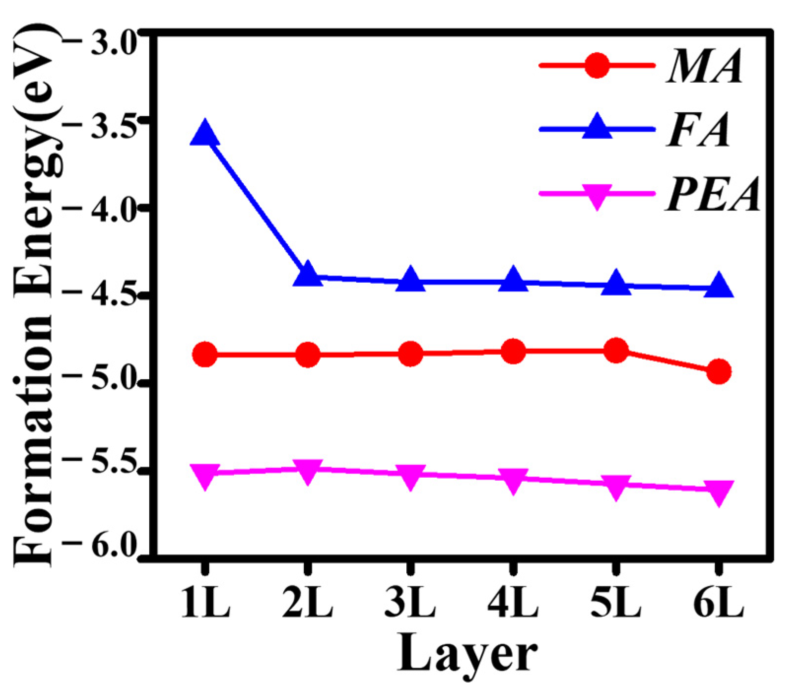
where Ef2D is the formation energy of the perovskite-like layers X2Cs(n−1)PbnI(3n+1); Etot and Ebulk are the total energy of X2Cs(n−1)PbnI(3n+1) and bulk CsPbI3, respectively; n is the number of corresponding perovskite-like layers; atom is the atom energy of simple substances; and EX is the energy of each molecule (MA, FA, and PEA). Figure 2 shows the formation energy of X2Cs(n−1)PbnI(3n+1) for the number of layers n = 1~6, in which X are MA, FA, and PEA, respectively, representing MA2Cs(n−1) PbnI (3n+1), FA2Cs (n−1) PbnI (3n+1), and PEA2Cs(n−1)PbnI(3n+1). The formation energy of X2Cs(n−1)PbnI(3n+1) (X = MA, FA, and PEA) decreases with the increase in layers. When the number of layers is greater than 3, the formation energy of X2Cs (n−1) PbnI (3n+1) (X = MA, FA, and PEA) remains unchanged. This implies that the structure of X2Cs(n−1)PbnI(3n+1) (X = MA, FA, and PEA) tends to be more stable with the increasing number of layers. Furthermore, we find that in the same layers, the formation energy of 2D perovskite-like perovskite is PEA2Cs(n−1)PbnI(3n+1) > MA2Cs(n−1)PbnI(3n+1) > FA2Cs(n−1)PbnI(3n+1), and (FA)2Cs(n−1)PbnI(3n+1) is more stable.

3.2. Electronic Structures

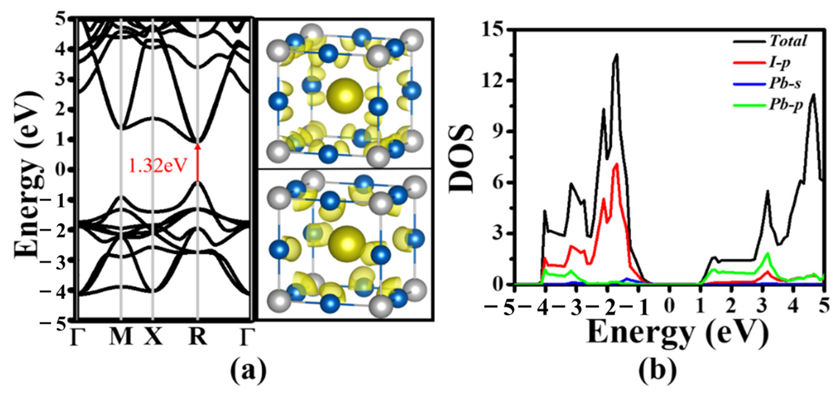
To obtain a deep understanding of the electronic property of these layered perovskite-like X2Cs(n−1)PbnI(3n+1) (n = 1~6), we calculate the structure and density of states (DOS) and the partial charge density of the bulk CsPbI3, as shown in Figure 3. The band gap of cubic perovskite CsPbI3 is ~1.32 eV (Figure 3a), which is consistent with the previous calculation results [26]. It is seen that the conduction band minimum (CBM) and valence band maximum (VBM) are mainly composed of the Pb-p orbital and the I-p orbital (Figure 3a), respectively, and DOS is also consistent with the previous analysis (Figure 3b).
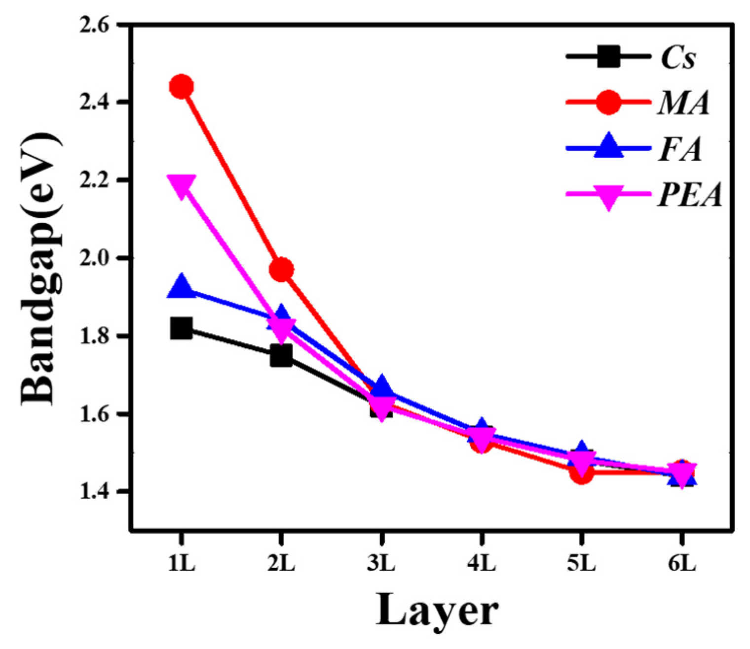
The band gap was calculated using the PBE approximation. The change in the 2D perovskite-like X2Cs(n−1)PbnI(3n+1) (n = 1~6) bandgap X2Cs(n−1) PbnI(3n+1) (n = 1~6) with increasing layers is presented in Figure 4. At the same passivation ligand, the band gap gradually decreases with increasing layers, which is consistent with previous reports. As the number of layers increased, the band gap of MA2Cs(n−1)PbnI(3n+1) changed from 2.44 eV to 1.45 eV, the band gap of FA2Cs(n−1)PbnI (3n+1) changed from 1.92 eV to 1.44 eV, and the band gap of PEA2Cs(n−1) PbnI(3n+1) changed from 2.19 eV to 1.45 eV. The band gap of X2Cs(n−1)PbnI(3n+1) (X = MA, FA, and PEA) is less than 1.6 eV when the number of layers increased to 3. Our calculations indicate that 2D perovskite-like X2Cs(n−1)PbnI(3n+1) (n > 3) are suitable materials for solar cells.
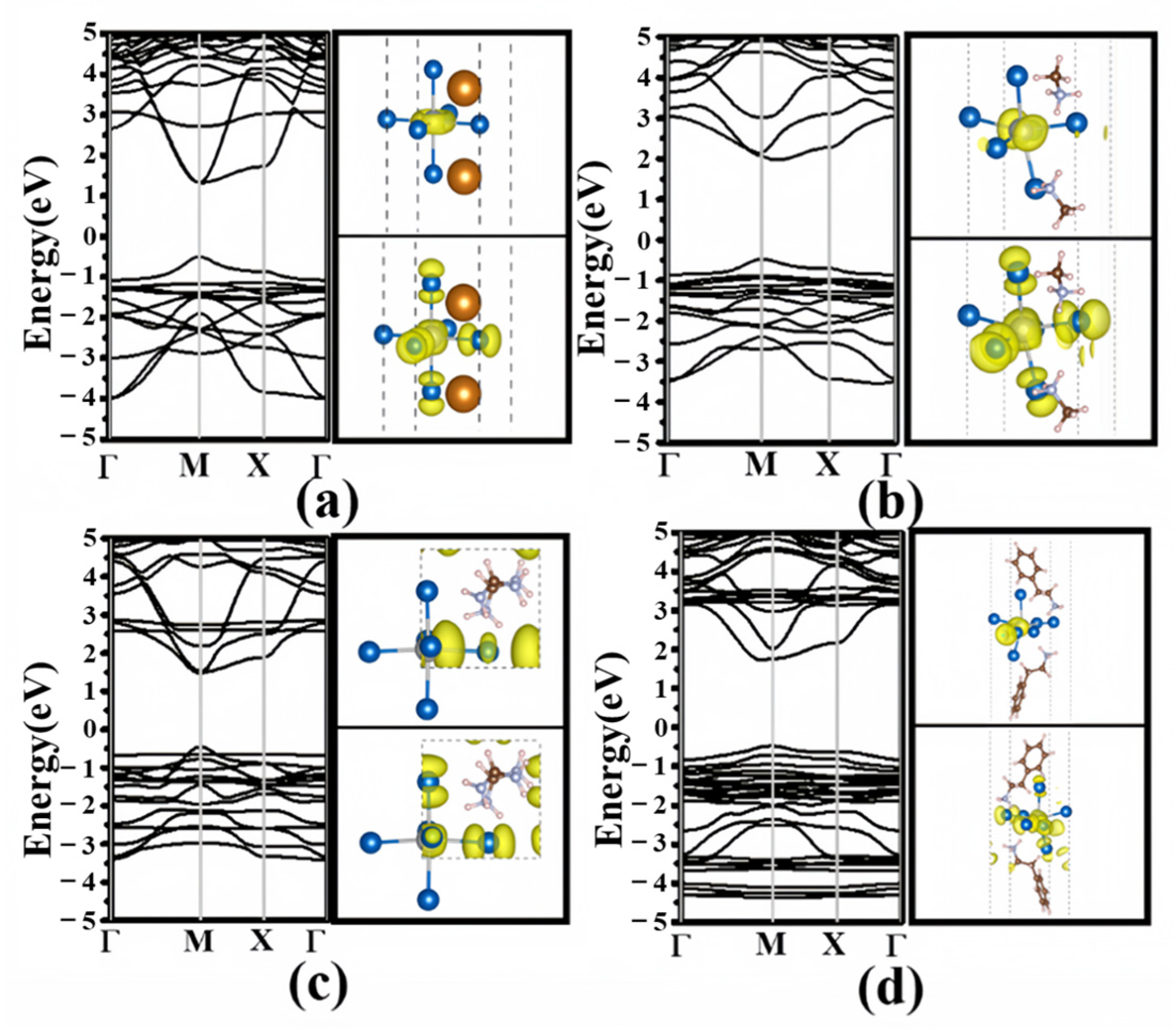
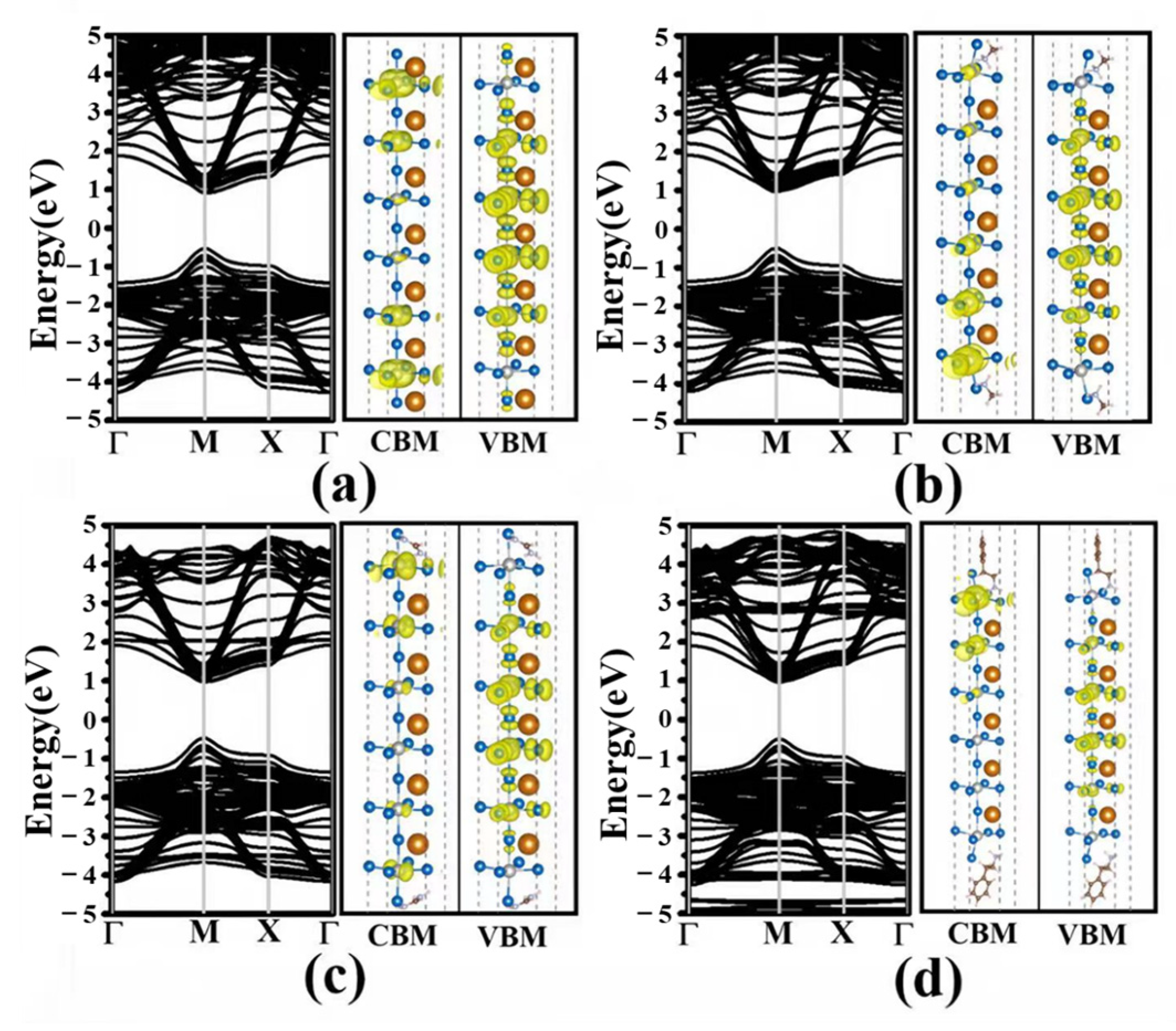
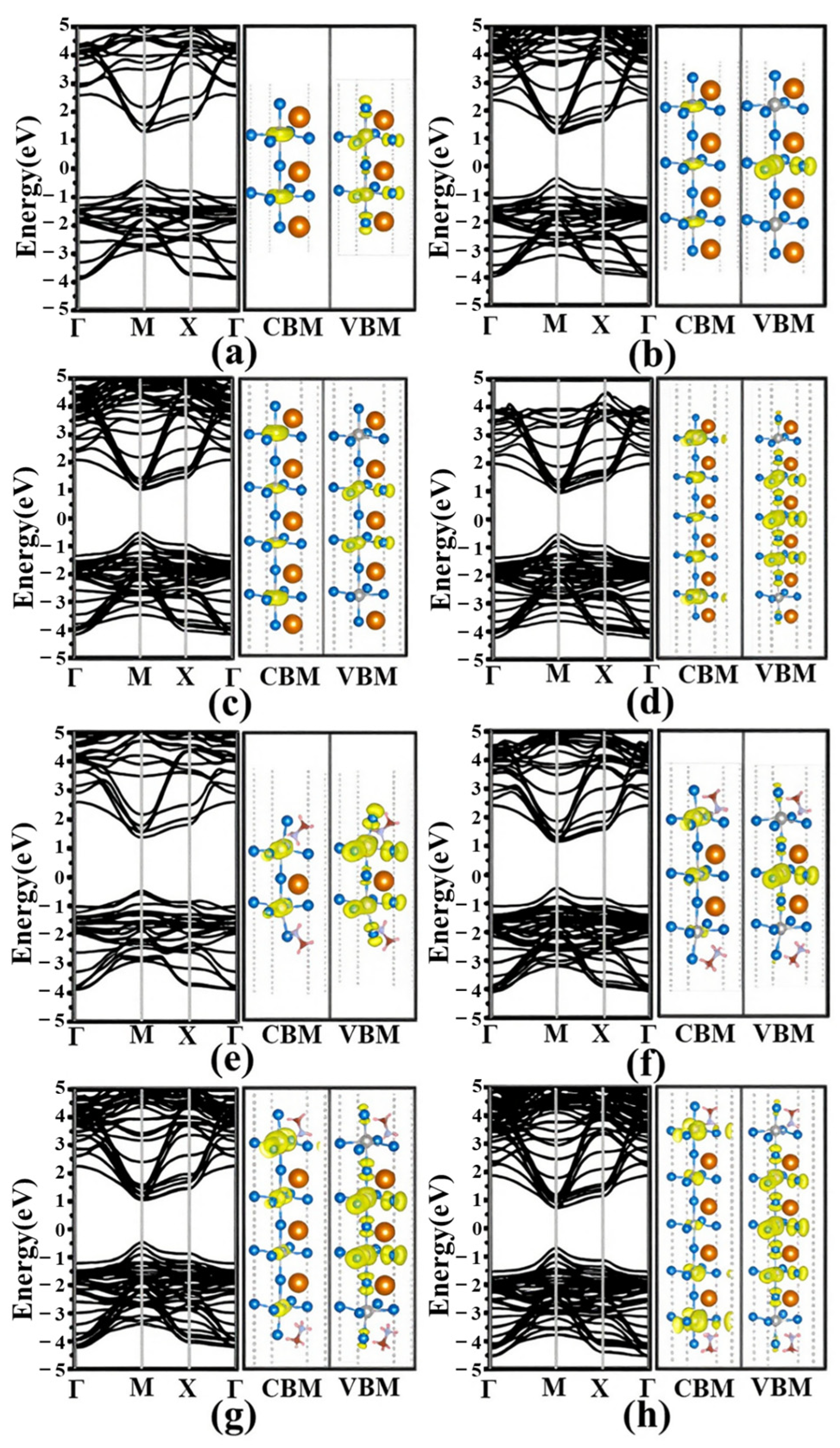
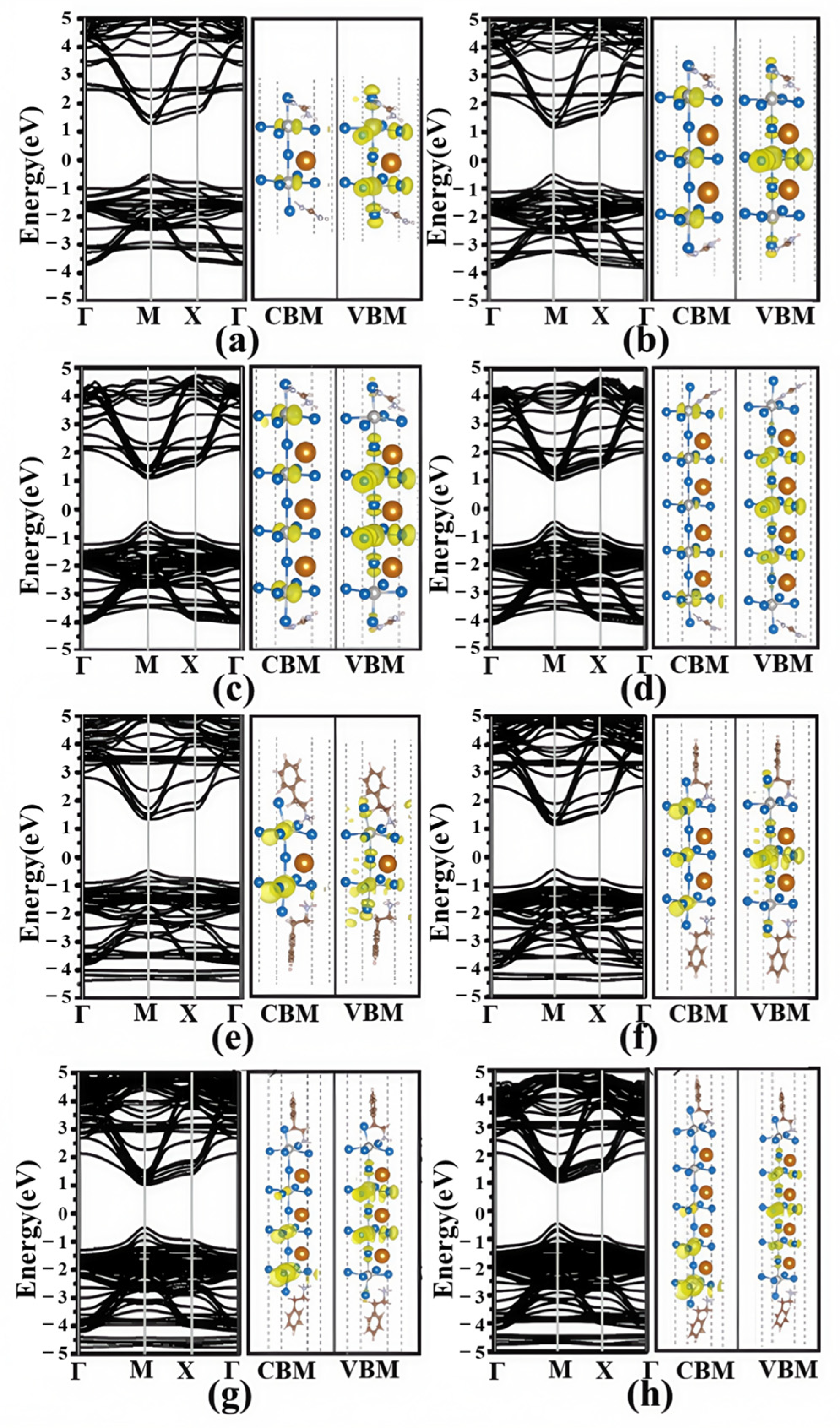
The band structure and the corresponding partial charge density of Cs(n−1)PbnI(3n+1) (n = 1, 6) and X2Cs(n−1)PbnI(3n+1) (X = MA, FA, and PEA; n = 1, 6) are shown in Figure 5 and Figure 6, while the band structure and the corresponding partial charge density for other calculated structures with n = 2~5 are shown in Figure 7 and Figure 8. In the case of Cs(n−1)PbnI(3n+1) (n = 1, 6) and X2Cs(n−1)PbnI(3n+1) (X = MA, FA, and PEA; n = 1, 6), both the maximum valence band (VBM) and the minimum conduction band (CBM) are at the M point. The valence and conduction bands are mainly contributed by the inorganic framework Pb-I, VBM is mainly contributed by the 5p orbit of I, and CBM is mainly contributed by the 6p orbit of Pb. As the number of layers increases, the charge density at CBM and VBM presents a good separation state, and the charge of CBM is mainly contributed by the outer framework at both ends, while the charge of VBM is mainly concentrated at the center of the inner layer. Furthermore, the results of the band structure calculation show that X2Cs(n−1)PbnI(3n+1) (X = MA, PEA; n = 1) is an indirect band gap, while X2Cs(n−1)PbnI(3n+1) (X = MA, PEA; n = 2~6) is a direct band gap. This phenomenon may be related to the distortion of the structure.
To validate the accuracy of our computational methods, we systematically compared our calculated results with available experimental data. As summarized in Table 2, the calculated bandgap of bulk CsPbI3 (1.32 eV) shows a reasonable agreement with experimental values (1.73 eV) [26,27], with the discrepancy attributed to the well-known bandgap underestimation of the PBE functional. For quasi-2D perovskites, our calculations demonstrate excellent consistency in the layer-dependent bandgap trends. Specifically, the PEA-passivated system at n = 3 shows a calculated bandgap of 1.45 eV, closely matching experimental reports (~1.55 eV) [19,20]. Similarly, the calculated bandgap of 2D (BA)2CsPb2Br7 (2.5 eV) follows the experimental trend (2.9 eV) [19], with the difference likely arising from excitonic effects not fully captured by DFT. These comparisons confirm that while absolute values may vary due to theoretical limitations, our calculations reliably reproduce the key experimental trends in both bandgap evolution and passivation effects.
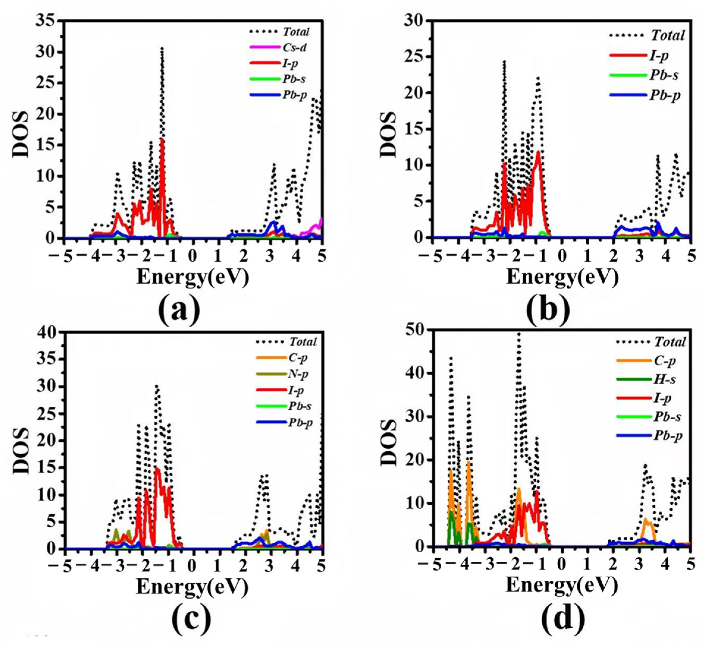
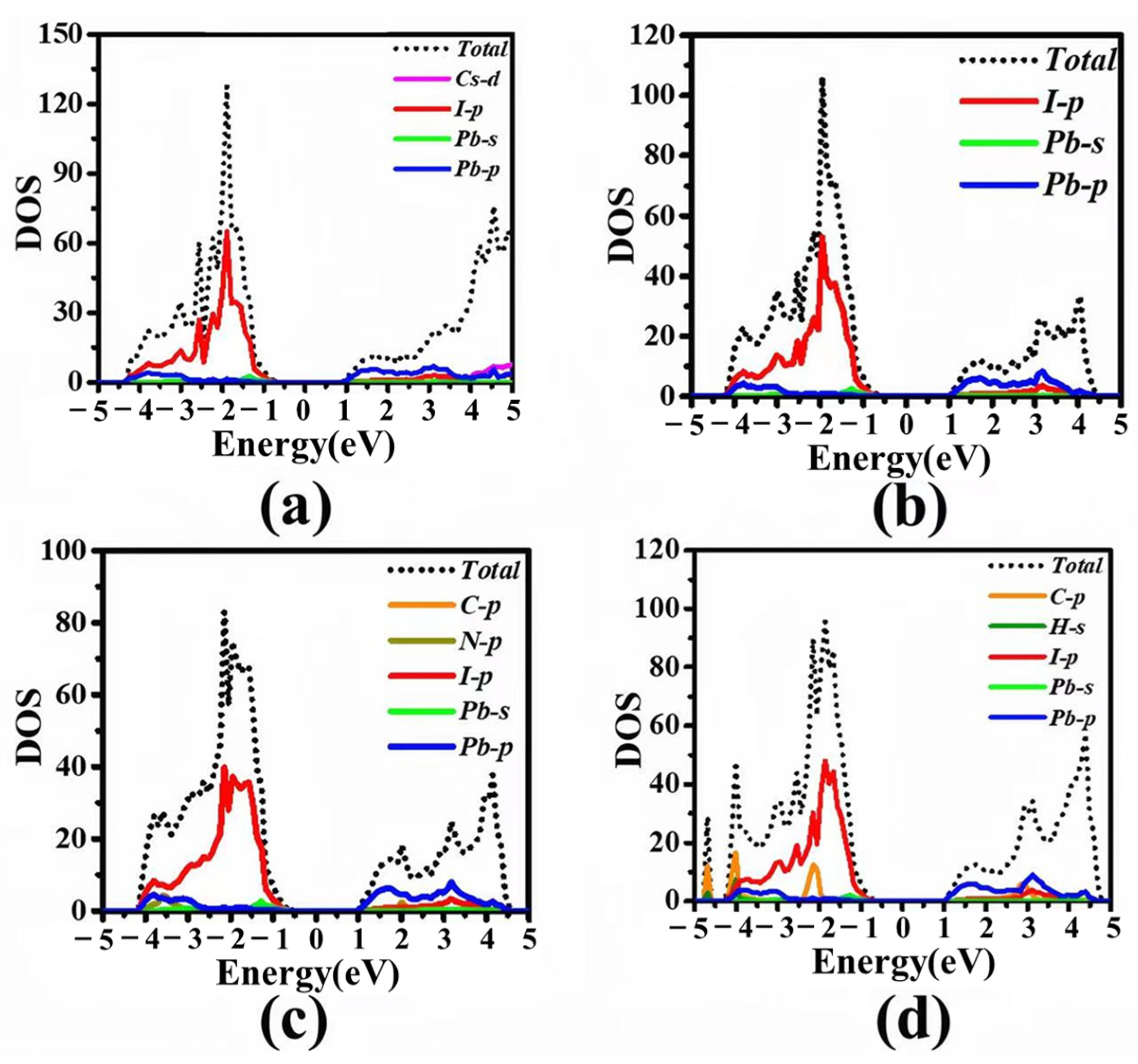
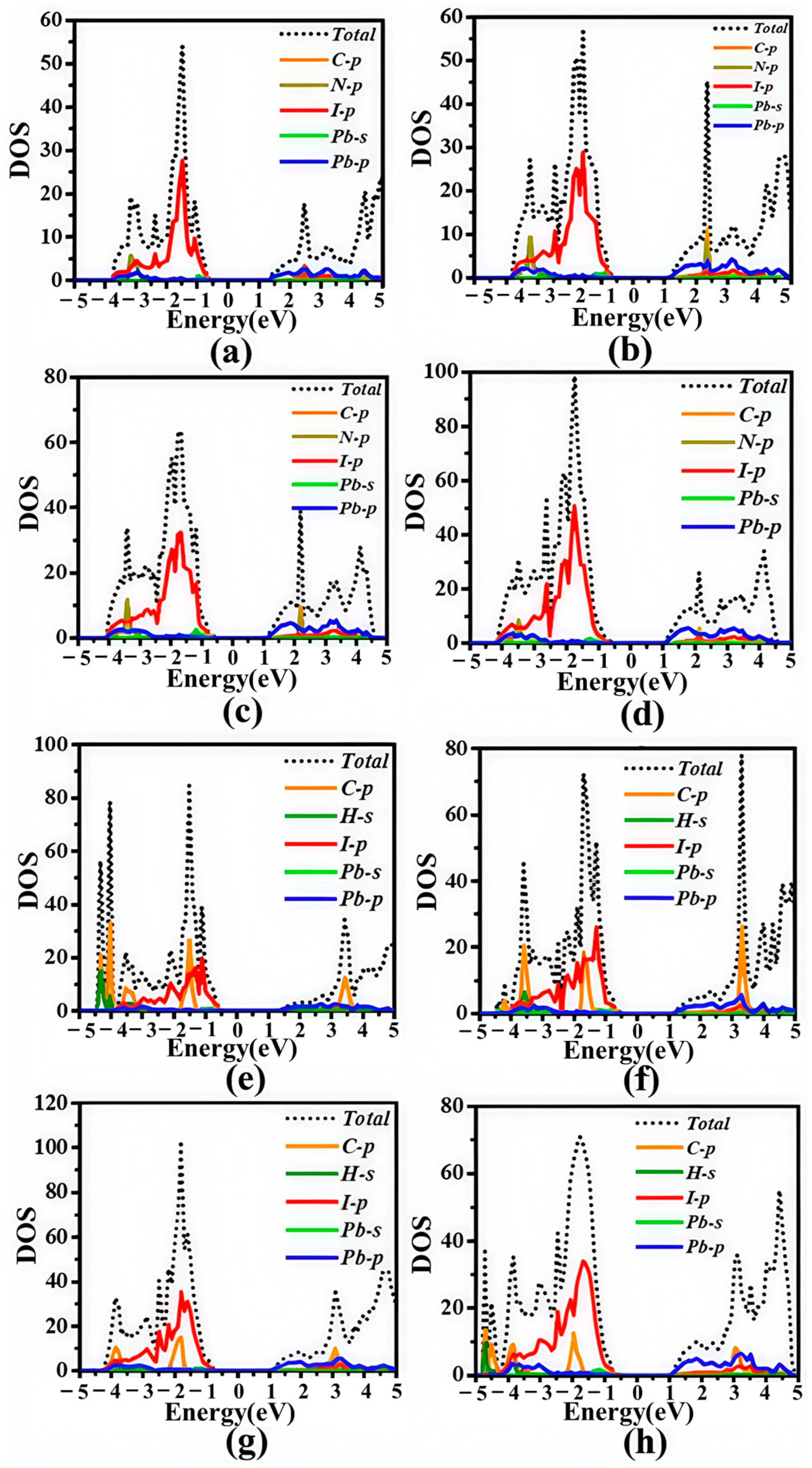
To further understand the nature of the valence and conduction bands, the density of state (DOS) characteristics of Cs(n−1)PbnI(3n+1) (n = 1, 6) and X2Cs(n−1)PbnI(3n+1) (X = MA, FA, and PEA; n = 1, 6) were also simulated, and are shown in Figure 9 and Figure 10. The DOS characteristics of X2Cs(n−1)PbnI(3n+1) (X = MA, FA, and PEA; n = 2~5) are shown in Figure 11 and Figure 12. As shown in Figure 7a and Figure 8e, Figure 7b and Figure 8f, Figure 7c and Figure 8g and Figure 7d and Figure 8h, with the change in n from 1 to 6, the band gap becomes smaller, mainly due to the downward movement of the CBM. The electronic structure is mainly composed by the Pb-I inorganic framework, where CBM contributes mainly by the 6p orbit of Pb and VBM contributes mainly by the 5p orbit of I. These results are consistent with the previous conclusion.

3.3. Effective Mass and Optical Properties

To better understand the photoelectric properties of the materials, the effective mass of X2Cs(n−1)PbnI(3n+1) (X = MA, FA, and PEA) was calculated. The effective mass is calculated as follows:
m * = ħ 2 2 E k 2 1
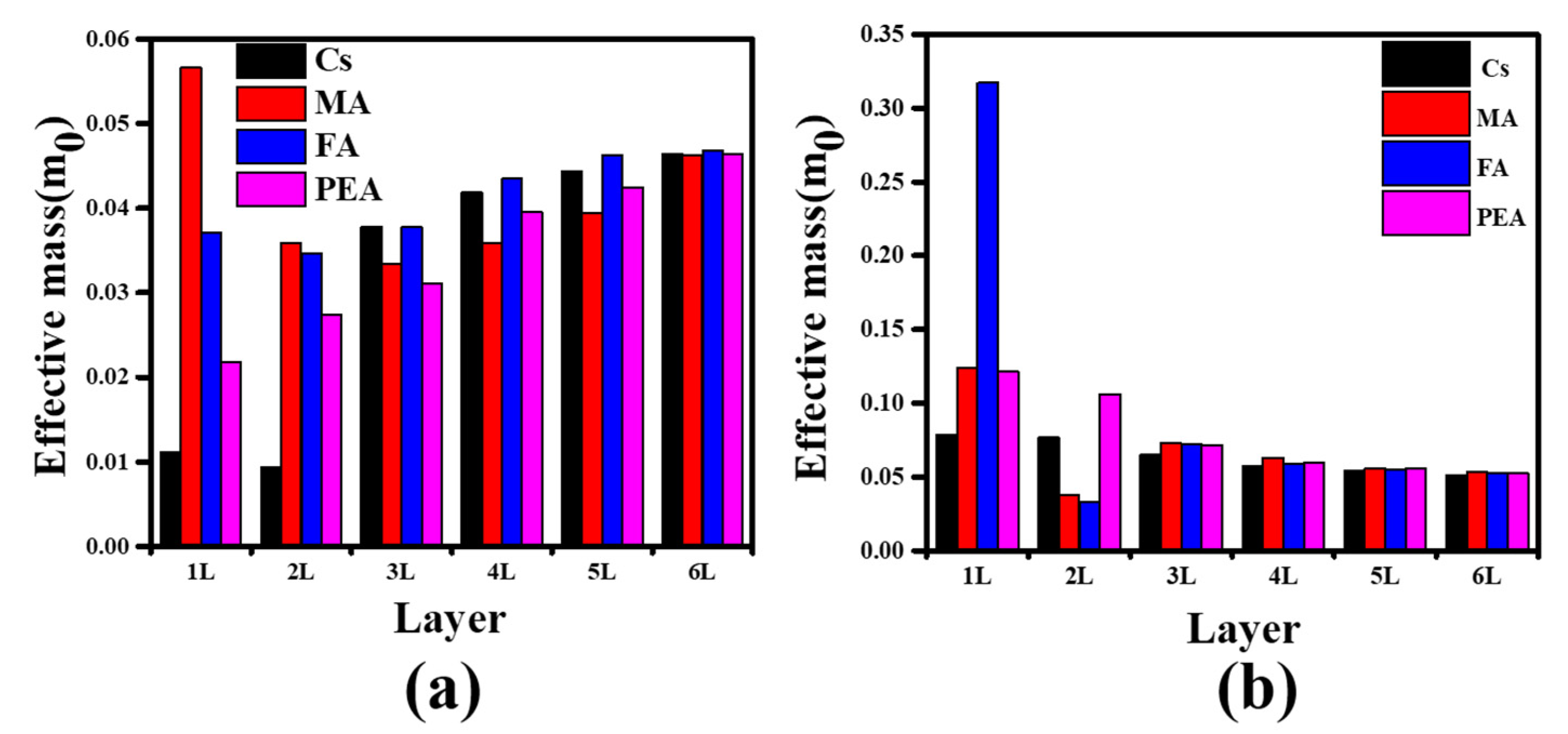
where ħ is the reduced Planck constant, k is the magnitude of the wave vector in momentum space, and ∂2E/∂k2 is obtained by fitting the energy dispersion curves near the CBM and VBM, respectively. The effective mass that differs with the number of layers in different passivation groups CBM (me*) and VBM (mh*) is presented in Figure 13. Our results show that the valve of mh* decreases from 0.3171m0 to 0.0513m0, while the valve of me* increases from 0.0111m0 to 0.0468m0 with increasing number of layers. It is obvious that the valve of me* of MA2Cs(n−1)PbnI(3n+1) and the valve of mh* of FA2Cs(n−1)PbnI(3n+1) have the maximum in one layer. As the number of layers increases, the valve of me* or mh* tends to be the same. We observe that the photoelectric conversion efficiency of Cs(n−1)PbnI(3n+1) is better than X2Cs(n−1)PbnI(3n+1) (X = MA, FA, and PEA) when the n < 3, while the photoelectric conversion efficiency of all structures tends to the same when n ≥ 4. The results indicated that the increase in layers has a small effect on the photoelectric conversion efficiency.
Optical absorption is an important parameter for evaluating the photoelectric properties of materials. The optical response of a material to incident light is described by the complex dielectric function ε(ω) =ε1(ω) ± iε2(ω), where ε(ω) is usually used to describe the linear response of crystals to electromagnetic radiation, ε1(ω) is related to the electronic polarizability of a material, whereas ε2(ω) gives information about the absorption behavior of a crystal. The absorption coefficient α(ω) is defined as per the following equation:
α ω = 2 ω c ħ ( ε 1 2 + ε 2 2 ε 1 2 ) 1 2
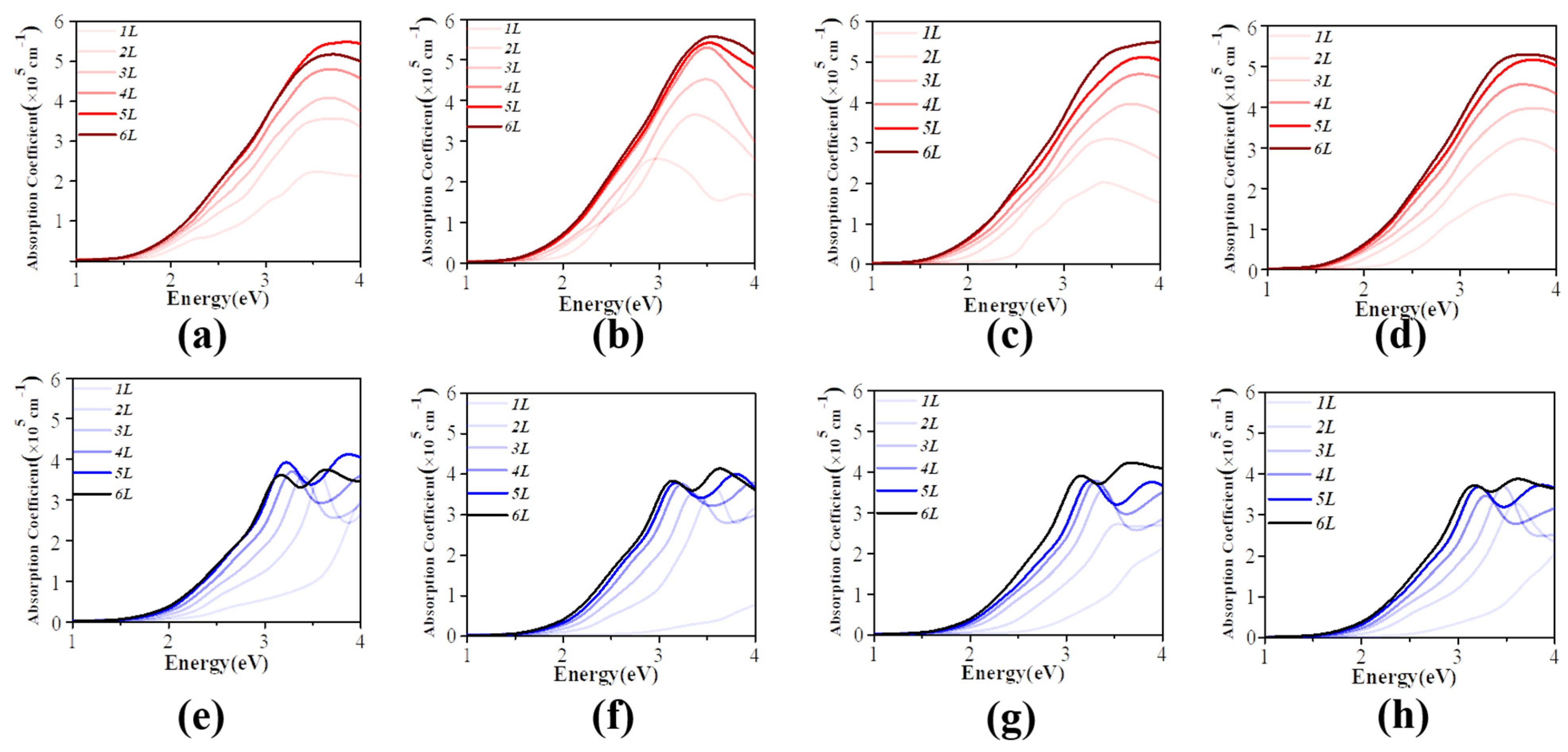
where ω stands for phonon frequency and c is the speed of light in vacuum. The absorption coefficient of X2Cs(n−1)PbnI(3n+1) (X = MA, FA, and PEA) changes with different layers in the Y direction and in the Z direction, as shown in Figure 11. For the same group of passivation, the optical absorption spectrum shows a red shift with the increase in the number of layers, which is consistent with the previous results of the band gap. As shown in Figure 14, the highest among the peaks corresponds to X2Cs(n−1)PbnI(3n+1) (X = MA, FA, and PEA) with a maximum value of 3.5 eV. The absorption coefficient increases with the increase in layers. It can be observed that the absorption coefficient of Cs(n−1)PbnI(3n+1) (n = 6) is less than that of Cs (n−1) PbnI (3n + 1) (n = 5), which may be due to the structure of Cs (n−1) PbnI (3n + 1) (n = 6) being similar to a bulk CsPbI3. From the absorption spectra, there are two obvious optical absorption peaks in the Z direction, and the first absorption peak appears at 3.0 eV. The absorption intensity in the Z direction is significantly lower than that in the Y direction. It can be concluded that the quasi-two-dimensional perovskite X2Cs(n−1)PbnI(3n+1) (X = MA, FA, and PEA) exhibits anisotropy in absorption spectra, which favors its application in solar cells and optical sensors.

4. Conclusions

This study presents a comprehensive theoretical investigation of surface-passivated quasi-2D perovskites, revealing fundamental insights into their structure–property relationships. Through systematic first-principles calculations, we demonstrate that organic cation passivation (MA, FA, PEA) effectively stabilizes the perovskite structure while preserving favorable optoelectronic characteristics when the layer number exceeds three. The FA-passivated system emerges as particularly promising, exhibiting superior thermodynamic stability attributed to its optimal molecular configuration and bonding characteristics. Our analysis of the electronic structure evolution shows a clear convergence towards bulk-like properties beyond three layers, with bandgaps stabilizing below 1.6 eV—a crucial threshold for photovoltaic applications. The observed anisotropic optical absorption, showing significantly enhanced in-plane compared to out-of-plane response, provides valuable design guidelines for device engineering. These findings establish important materials selection criteria and fabrication strategies for developing stable, high-performance quasi-2D perovskite optoelectronic devices. The computational framework developed here offers a robust platform for future exploration of novel perovskite derivatives with tailored properties, while the fundamental understanding gained bridges the gap between atomic-scale modifications and macroscopic device performance. This work contributes to the rational design of next-generation perovskite materials with improved stability and functionality for advanced optoelectronic applications.
In the future, anisotropic absorption can be further optimized through halide alloying (Br/I mixing) and vertical heterostructures within the density functional theory (DFT) framework.

Author Contributions

M.L.: Conceptualization, formal analysis, original draft writing, resources, software. H.Z.: Data curation, investigation. Formal analysis, Methodology. X.K.: Validation, Visualization, Visualization. J.H. Validation, Writing—review and editing. D.Z.: Funding acquisition, Project administration, Supervision, Writing—review and editing. All authors have read and agreed to the published version of the manuscript.

Funding

This research was funded by [China National Natural Science Foundation] grant number [22174133].

Data Availability Statement

Data will be available upon request.

Acknowledgments

Thank you to P.L. for providing guidance in research design and paper revision. Thank you to J.P. for providing assistance in submitting and revising the paper. The anonymous reviewers have also contributed considerably to the publication of this paper.

Conflicts of Interest

The authors declare that they have no known competing financial interests or personal relationships that could appear to influence the work reported in this paper.

References

  1. Jung, E.H.; Jeon, N.J.; Park, E.Y.; Moon, C.S.; Shin, T.J.; Yang, T.-Y.; Noh, J.H.; Seo, J. Efficient, stable and scalable perovskite solar cells using poly(3-hexylthiophene). Nature 2019, 567, 511–515. [Google Scholar] [CrossRef]
  2. Kim, M.; Jeong, J.; Lu, H.; Lee, T.K. Conformal quantum dot–SnO2 layers as electron transporters for efficient perovskite solar cells. Science 2022, 375, 302–306. [Google Scholar] [CrossRef]
  3. Zhao, J.; Zhao, L.; Deng, Y.; Xiao, X.; Ni, Z.; Xu, S.; Huang, J. Perovskite-filled membranes for flexible and large-area direct-conversion X-ray detector arrays. Nat. Photonics 2020, 14, 612–617. [Google Scholar] [CrossRef]
  4. Veldhuis, S.A.; Boix, P.P.; Yantara, N.; Li, M.; Sum, T.C.; Mathews, N.; Mhaisalkar, S.G. Perovskite Materials for Light-Emitting Diodes and Lasers. Adv. Mater. 2016, 28, 6804–6834. [Google Scholar] [CrossRef]
  5. Turren-Cruz, S.-H.; Saliba, M.; Mayer, M.T.; Juárez-Santiesteban, H.; Mathew, X.; Nienhaus, L.; Tress, W.; Erodici, M.P.; Sher, M.-J.; Bawendi, M.G.; et al. Enhanced charge carrier mobility and lifetime suppress hysteresis and improve efficiency in planar perovskite solar cells. Energy Environ. Sci. 2018, 11, 78–86. [Google Scholar] [CrossRef]
  6. Stranks, S.D.; Eperon, G.E.; Grancini, G.; Menelaou, C.; Alcocer, M.J.P.; Leijtens, T.; Herz, L.M.; Petrozza, A.; Snaith, H.J. Electron-Hole Diffusion Lengths Exceeding 1 Micrometer in an Organometal Trihalide Perovskite Absorber. Science 2013, 342, 341–344. [Google Scholar] [CrossRef]
  7. Protesescu, L.; Yakunin, S.; Bodnarchuk, M.I.; Krieg, F.; Caputo, R.; Hendon, C.H.; Yang, R.X.; Walsh, A.; Kovalenko, M.V. Nanocrystals of Cesium Lead Halide Perovskites (CsPbX3, X = Cl, Br, and I): Novel Optoelectronic Materials Showing Bright Emission with Wide Color Gamut. Nano Lett. 2015, 15, 3692–3696. [Google Scholar] [CrossRef]
  8. Lin, K.; Xing, J.; Quan, L.N.; de Arquer, F.P.G.; Gong, X.; Lu, J.; Xie, L.; Zhao, W.; Zhang, D.; Yan, C.; et al. Perovskite light-emitting diodes with external quantum efficiency exceeding 20 per cent. Nature 2018, 562, 245–248. [Google Scholar] [CrossRef]
  9. Best-Research-Cell-Efficiencies.pdf. (n.d.). Available online: https://www.nrel.gov/pv/assets/pdfs/best-research-cell-efficiencies.pdf (accessed on 8 November 2024).
  10. Kwak, K.; Lim, E.; Ahn, N.; Heo, J.; Bang, K.; Kim, S.K.; Choi, M. An atomistic mechanism for the degradation of perovskite solar cells by trapped charge. Nanoscale 2019, 11, 11369–11378. [Google Scholar] [CrossRef]
  11. Chowdhury, T.A.; Bin Zafar, M.A.; Sajjad-Ul Islam, M.; Shahinuzzaman, M.; Islam, M.A.; Khandaker, M.U. Stability of perovskite solar cells: Issues and prospects. RSC Adv. 2023, 13, 1787–1810. [Google Scholar] [CrossRef]
  12. Wolff, C.M.; Caprioglio, P.; Stolterfoht, M.; Neher, D. Nonradiative Recombination in Perovskite Solar Cells: The Role of Interfaces. Adv. Mater. 2019, 31, 1902762. [Google Scholar] [CrossRef]
  13. Gong, J.; Hao, M.; Zhang, Y.; Liu, M.; Zhou, Y. Layered 2D Halide Perovskites beyond the Ruddlesden–Popper Phase: Tailored Interlayer Chemistries for High-Performance Solar Cells. Angew. Chem. 2022, 134, e202112022. [Google Scholar] [CrossRef]
  14. Ke, W.; Kanatzidis, M.G. Prospects for low-toxicity lead-free perovskite solar cells. Nat. Commun. 2019, 10, 965. [Google Scholar] [CrossRef]
  15. Stoumpos, C.C.; Cao, D.H.; Clark, D.J.; Young, J.; Rondinelli, J.M.; Jang, J.I.; Hupp, J.T.; Kanatzidis, M.G. Ruddlesden–Popper Hybrid Lead Iodide Perovskite 2D Homologous Semiconductors. Chem. Mater. 2016, 28, 2852–2867. [Google Scholar] [CrossRef]
  16. Gao, L.; Spanopoulos, I.; Ke, W.; Huang, S.; Hadar, I.; Chen, L.; Li, X.; Yang, G.; Kanatzidis, M.G. Improved Environmental Stability and Solar Cell Efficiency of (MA,FA)PbI3 Perovskite Using a Wide-Band-Gap 1D Thiazolium Lead Iodide Capping Layer Strategy. ACS Energy Lett. 2019, 4, 1763–1769. [Google Scholar] [CrossRef]
  17. Umeyama, D.; Lin, Y.; Karunadasa, H.I. Red-to-Black Piezochromism in a Compressible Pb–I–SCN Layered Perovskite. Chem. Mater. 2016, 28, 3241–3244. [Google Scholar] [CrossRef]
  18. Shi, W.; Ye, H. Efficient and Stable Perovskite Solar Cells with a Superhydrophobic Two-Dimensional Capping Layer. J. Phys. Chem. Lett. 2021, 12, 4052–4058. [Google Scholar] [CrossRef]
  19. Wang, Y.; Song, Q.; Hu, W.; Wang, D.; Peng, L.; Shi, T.; Liu, X.; Zhu, Y.; Lin, J. Temperature-driven phase transition and transition dipole moment of two-dimensional (BA)2CsPb2Br7 perovskite. Phys. Chem. Chem. Phys. 2021, 23, 16341–16348. [Google Scholar] [CrossRef]
  20. Feng, Z.; Xia, Z.; Wu, Z.; Hua, Y.; Zhu, G.; Chen, X.; Huang, S. Efficient and stable perovskite solar cells via organic surfactant interfacial passivation. Sol. Energy 2021, 227, 438–446. [Google Scholar] [CrossRef]
  21. Wang, D.; Liang, P.; Dong, Y.; Shu, H.; Liu, Z. Electronic and optical properties of layered Ruddlesden Popper hybrid X2(MA)n-1SnnI3n+1 perovskite insight by first principles. J. Phys. Chem. Solids 2020, 144, 109510. [Google Scholar] [CrossRef]
  22. Kresse, G.; Furthmüller, J. Efficient iterative schemes for ab initio total-energy calculations using a plane-wave basis set. Phys. Rev. B 1996, 54, 11169–11186. [Google Scholar] [CrossRef]
  23. Blöchl, P.E. Projector augmented-wave method. Phys. Rev. B 1994, 50, 17953–17979. [Google Scholar] [CrossRef]
  24. Körbel, S.; Marques, M.A.L.; Botti, S. Stability and electronic properties of new inorganic perovskites from high-throughput ab initio calculations. J. Mater. Chem. C 2016, 4, 3157–3167. [Google Scholar] [CrossRef]
  25. Quan, L.N.; Yuan, M.; Comin, R.; Voznyy, O.; Beauregard, E.M.; Hoogland, S.; Buin, A.; Kirmani, A.R.; Zhao, K.; Amassian, A.; et al. Ligand-stabilized reduced-dimensionality perovskites. J. Am. Chem. Soc. 2016, 138, 2649–2655. [Google Scholar] [CrossRef] [PubMed]
  26. Ahmad, M.; Rehman, G.; Ali, L.; Shafiq, M.; Iqbal, R.; Ahmad, R.; Khan, T.; Jalali-Asadabadi, S.; Maqbool, M.; Ahmad, I. Structural, electronic and optical properties of CsPbX3 (X = Cl, Br, I) for energy storage and hybrid solar cell applications. J. Alloys Compd. 2017, 705, 828–839. [Google Scholar] [CrossRef]
  27. Fang, Z.; Shang, M.; Hou, X.; Zheng, Y.; Du, Z.; Yang, Z.; Chou, K.-C.; Yang, W.; Wang, Z.L.; Yang, Y. Bandgap alignment of α-CsPbI3 perovskites with synergistically enhanced stability and optical performance via B-site minor doping. Nano Energy 2019, 61, 389–396. [Google Scholar] [CrossRef]
  28. Perdew, J.P.; Ernzerhof, M.; Burke, K. Rationale for mixing exact exchange with density functional approximations. J. Chem. Phys. 1996, 105, 9982–9985. [Google Scholar] [CrossRef]
  29. Grimme, S.; Antony, J.; Ehrlich, S.; Krieg, H. A consistent and accurate ab initio parametrization of density functional dispersion correction (DFT-D) for the 94 elements H-Pu. J. Chem. Phys. 2010, 132, 154104. [Google Scholar] [CrossRef]
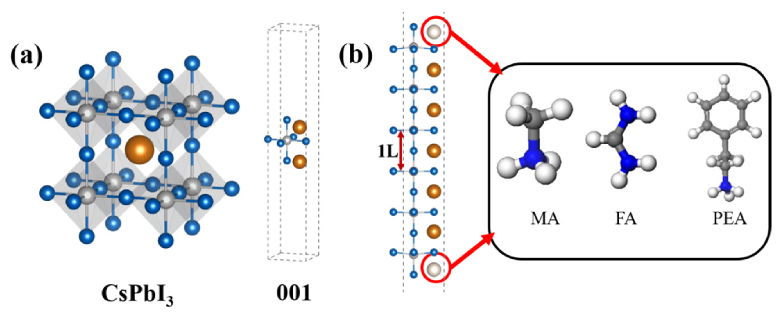
Figure 1. (a) Structures of bulk perovskite CsPbI3 and (b) layered perovskite-like X2Cs(n−1) PbnI(3n+1) (X = CH3NH3 + (MA), (NH2)2CH+ (FA), and C6H5(CH2)2NH3+ (PEA); n = 1~6).
Condensedmatter 10 00044 g001
Figure 2. The formation energy of different functional clusters absorbed in the layered perovskite-like X2Cs(n−1) PbnI(3n+1) (X = MA, FA, and PEA).
Condensedmatter 10 00044 g002
Figure 3. Band structure, DOS, and partial charge density of cubic CsPbI3: (a) band structure and partial charge density; (b) DOS.
Condensedmatter 10 00044 g003
Figure 4. Variation in the 2D perovskite-like X2Cs(n−1)PbnI(3n+1) (X = MA, FA, and PEA; n = 1~6) bandgap by changing the number of layers.
Condensedmatter 10 00044 g004
Figure 5. Band structure and partial decomposed charge density of CBM and VBM in X2Cs(n−1)PbnI(3n+1) (n = 1): (a) without passivation, (b) X = MA, (c) X = FA, and (d) X = PEA. The Fermi energy level is set to zero.
Condensedmatter 10 00044 g005
Figure 6. Band structure and partial decomposed charge density of CBM and VBM in X2Cs(n−1)PbnI(3n+1) (n = 6): (a) without passivation, (b) X = MA, (c) X = FA, and (d) X = PEA. The fermi energy level is set to zero.
Condensedmatter 10 00044 g006
Figure 7. Band structure and decomposed partial charge density of the CBM and VBM in X2Cs(n−1)PbnI(3n+1) (n = 2, 3, 4, 5; from left to right): (ad) no passivation,(eh) X=MA.The fermi energy level is set as zero.
Condensedmatter 10 00044 g007
Figure 8. Band structure and decomposed partial charge density of the CBM and VBM in X2Cs(n−1)PbnI(3n+1) (n = 2, 3, 4, 5; from left to right): (ad) X = FA, (eh) X = PEA. The fermi energy level is set as zero.
Condensedmatter 10 00044 g008
Figure 9. DOS of X2Cs(n−1)PbnI(3n+1), where (a) do not passivate for n = 1, while X = MA (b), FA (c), and PEA (d) for n= 1.
Condensedmatter 10 00044 g009
Figure 10. DOS of X2Cs(n−1)PbnI(3n+1), where (a) do not passivate for n = 6, while X = MA (b), FA (c), and PEA (d) for n = 6.
Condensedmatter 10 00044 g010
Figure 11. DOS of X2Cs(n−1)PbnI(3n+1) (n = 2, 3, 4, 5; from left to right): (ad) no passivation, (eh) X= MA.
Condensedmatter 10 00044 g011
Figure 12. DOS of X2Cs(n−1)PbnI(3n+1) (n = 2, 3, 4, 5; from left to right): (ad) X= FA, (eh) X = PEA.
Condensedmatter 10 00044 g012
Figure 13. Effective masses of (a) electron and (b) hole in X2Cs(n−1)PbnI(3n+1) (X = MA, FA, and PEA).
Condensedmatter 10 00044 g013
Figure 14. Optical absorption spectra for X2Cs(n−1)PbnI(3n+1) (X = MA, FA, and PEA; n = 1~6) (a,e) are without passivation; (b,f) are X = FA; (c,g) are X = MA and (d,h) are X = PEA. The top is the Y-axis, and the bottom is the Z-axis.
Condensedmatter 10 00044 g014
Table 1. Relevant parameters of different types of perovskites containing FA, MA, and PEA.
ParameterMA-BasedFA-BasedPEA-Based
Lattice param (Å)6.296.356.42
Bandgap (eV)1.451.441.45
ΔH_form (eV)−0.82−0.91−0.76
me/m00.0460.0430.048
MethodPBEPBEPBE
Table 2. Comparison table of calculation value and available experimental value.
PropertyCalculated Value Experimental Value
(This Work)(Literature)
Bulk CsPbI3 Bandgap1.32 V 1.73 eV
Quasi-2D PEA-Passivated 1.45 eV~1.55 eV
Bandgap (n = 3)
2D(BA)2CsPb2Br7 Bandgap2.5 eV2.9 eV
Disclaimer/Publisher’s Note: The statements, opinions and data contained in all publications are solely those of the individual author(s) and contributor(s) and not of MDPI and/or the editor(s). MDPI and/or the editor(s) disclaim responsibility for any injury to people or property resulting from any ideas, methods, instructions or products referred to in the content.