Article

Mechanical Characterization and Dual-Layer Discrete Element Modeling of Mactra veneriformis

1
College of Mechanical and Power Engineering, Dalian Ocean University, Dalian 116023, China
2
College of Engineering, Shenyang Agricultural University, Shenyang 110866, China
3
College of China & New Zealand Collaboration, Dalian Ocean University, Dalian 116023, China
4
Key Laboratory of Facility Fisheries, Ministry of Education, Dalian 116023, China
5
Liaoning Province Marine Fishery Equipment Specialized Technology Innovation Center, Dalian 116023, China
*
Author to whom correspondence should be addressed.
Fishes 2025, 10(9), 429; https://doi.org/10.3390/fishes10090429
Submission received: 16 July 2025 / Revised: 18 August 2025 / Accepted: 26 August 2025 / Published: 1 September 2025
(This article belongs to the Section Aquatic Invertebrates)

Abstract

The discrete element model of Mactra veneriformis currently employs an oversimplified multi-sphere approach using EDEM’s Hertz–Mindlin model, assuming uniform shell–flesh mechanical properties. This study developed an advanced dual-layer flexible bonding model through comprehensive biomechanical testing. Mechanical properties and shell morphology were experimentally characterized to inform model development. Parameter optimization combined free-fall experiments with Plackett–Burman screening, steepest ascent method, and Box–Behnken RSM, yielding optimal contact parameters: flesh–flesh stiffness (X1) = 3.64 × 10¹¹ N/m3, shell–flesh interface (X3) = 1.48×10¹³ N/m3, shell–shell tangential stiffness (X6) = 3.23 × 10¹² N/m3, and normal strength (X7) = 8.35 × 10⁶ Pa. Validation showed only 4.89% deviation between simulated and actual drop tests, with hydraulic impact tests confirming excellent model accuracy. The developed model accurately predicts mechanical behavior and shell fracture patterns during harvesting operations. This research provides a validated numerical tool for optimizing clam cultivation and harvesting equipment design, offering significant potential to reduce shell damage while improving harvesting efficiency in bivalve aquaculture systems.
Key Contribution: This study developed a dual-layer discrete element model based on the Hertz–Mindlin with Bonding V2 contact model to simulate the mechanical behavior and shell fracture mechanisms of Mactra veneriformis. Through experimental design and parameter calibration, key bonding parameters were determined, and the model demonstrated high accuracy (relative error of only 4.89%) in free-fall and hydraulic jet impact tests, providing a reliable numerical tool for optimizing low-damage harvesting equipment design.

1. Introduction

Shellfish aquaculture plays a pivotal role in China’s fisheries sector. In 2023, the production of intertidal shellfish reached 1.67 × 10⁷ t, accounting for approximately 29% of the total aquaculture output and making significant contributions to both fishery economics and regional development [1]. Mactra veneriformis (commonly called white clam) is a major contributor to molluscan production. Taxonomically, it belongs to the phylum Mollusca, class Bivalvia, and is further classified under the order Venerida and family Mactridae. As an important edible shellfish resource in China’s coastal regions, M. veneriformis is not only prized for its delicate flavor but also contains bioactive components including high-quality proteins, minerals, and polyunsaturated fatty acids, making it a highly popular seafood product [2,3,4]. With the expansion of M. veneriformis cultivation and rising labor costs, the mechanization of harvesting processes has accelerated. Mechanical damage during harvesting is inevitable and significantly impacts storage and marketability, directly reducing yield and economic returns. Shell damage can be fatal to mollusks [5]. Moreover, cracked shells are visually unappealing to consumers. In M. veneriformis production, shell breakage during harvesting, grading, storage, and transportation is a major factor affecting shelf life and quality. The breakage rate during harvesting alone ranges from 5.25% to 11.10% [6,7]. Therefore, addressing mechanical damage during M. veneriformis harvesting is imperative.
A strong correlation exists between clam survival and shell integrity. Although clams possess certain reparative capabilities, shell damage exposes their soft tissues to bacterial invasion, significantly increasing mortality risk. Driven by natural selection, molluscan shells have evolved specialized microstructures that provide effective protection against predator attacks [8]. Particularly in recent years, extensive research has been conducted on the morphology, microstructure, and mechanical properties of clam shells [9,10,11,12]. Ma et al. [13] revealed the unique mechanical properties of hard clam shells, demonstrating a vertical bearing stress of 55 MPa with interlayer compressive strength twice that of the whole structure. The fracture behavior exhibited both ceramic-like brittleness and metallic-like slip characteristics, providing novel insights for shellfish processing equipment design. Mondal et al. [5] established that the ecological significance of damage depends more on severity than specific causes, developing a three-tier classification system based on damage intensity. Their work elucidated evolutionary strategies in bivalves for coping with environmental stresses, offering new perspectives on long-term adaptation mechanisms to mechanical damage. Fakayode [14] determined key parameters for clam processing equipment design through measurements of geometric dimensions, physical properties and frictional characteristics of hard clams, while emphasizing the necessity of considering shell influences during processing. Vasconcelos et al. [15] addressed shell damage caused by dredge harvesting in smooth clams (Callista chione) through mechanical testing and finite element simulation, proposing solutions for improved fishing gear design. Mu et al. [16] characterized the Manila clam (Ruditapes philippinarum) shell properties including microstructure, phase composition, microhardness, nanoindentation hardness and elastic modulus, complemented by quasi-static and orthogonal compression tests on live specimens, to inform harvesting machinery development.
Technological innovation is the foundation for promoting circular practices in multiple fields, especially digital technology and assessment technology [17]. The widespread application of finite element method (FEM) and discrete element method (DEM) has enabled researchers to investigate collision-induced damage characteristics and mechanisms in various materials through simulation experiments [18,19,20,21]. Guan et al. [22] quantified the damage susceptibility of fresh corn ears under different impact conditions using FEM simulation and response surface methodology, providing theoretical support for loss-reducing harvester design. Hou et al. [23] developed a multi-scale blueberry model integrating FEM simulation with drop tests, establishing a response surface prediction model to optimize blueberry harvesting and processing equipment. Zhang et al. [24] identified critical factors affecting water chestnut impact damage through coupled simulation and experimental approaches, offering theoretical foundations for postharvest equipment design. Lou et al. [25] calibrated the contact parameters of the M. veneriformis DEM model through coupled experimental–simulation methodology, providing critical data for seeding and harvesting equipment simulation. Kafashan et al. [26] developed a multi-sphere apple model and validated the accuracy of a nonlinear viscoelastic contact model, thereby optimizing fruit damage reduction simulation methods. Gai et al. [27] established a dual-layer flexible bonding model for potatoes with merely 3.25% experimental–simulation error, creating an effective tool for low-damage harvesting equipment design. Current R&D of M. veneriformis cultivation and processing equipment primarily relies on DEM simulation technology. However, existing DEM models oversimplify M. veneriformis as a homogeneous material and fail to account for material property differences between the shell and flesh. Although such single-layer bonding models can simulate basic impact damage, their inability to accurately capture critical shell fracture patterns and analyze damage mechanisms results in insufficient simulation accuracy, severely constraining equipment optimization and development.
This study aims to develop and validate a dual-layer discrete element (DEM) model of M. veneriformis based on experimentally measured mechanical properties and shell microstructure characteristics. The model simulates drop test responses and fracture behavior under harvesting disturbances to provide theoretical support for harvester design, with potential applications extended to related species. Specifically:
(1)
The mechanical properties of the fruit shell and flesh were characterized experimentally, and the microstructure of the fruit shell (SEM) was recorded to guide the anisotropy of the model;
(2)
A two-layer flexible adhesive discrete element model (DEM) with anisotropic fruit shell–fruit shell and fruit shell–flesh contacts was developed; key contact parameters were calibrated using drop test results via Plackett–Burman screening, steepest ascent search, and Box–Behnken response surface design;
(3)
The model was experimentally validated, focusing on peak force and observed fracture behavior; the adaptability and limitations of the developed model were analyzed.

2. Materials and Methods

2.1. Overview of Research Methods

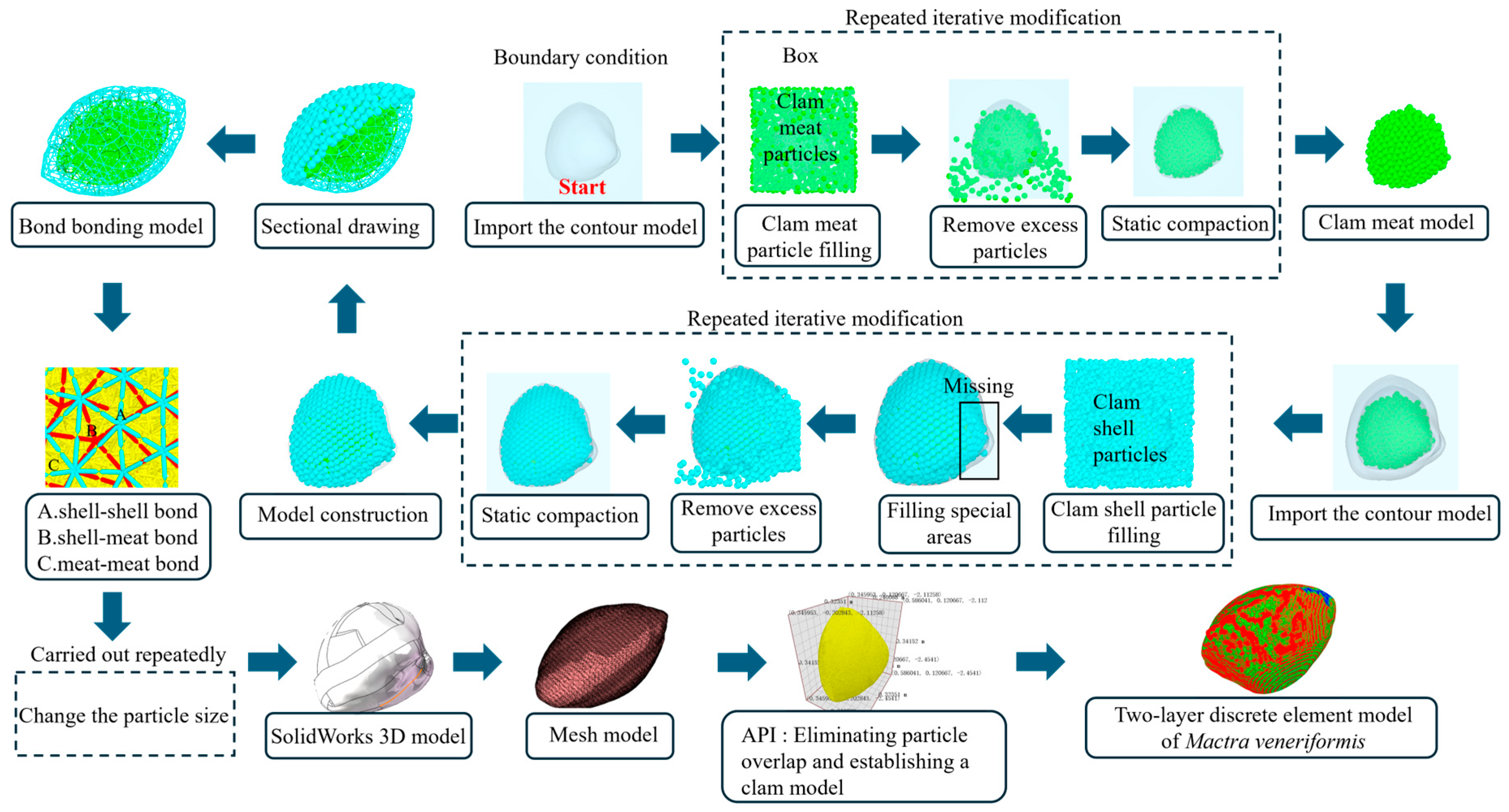
The experimental methodology flowchart is presented in Figure 1. First, intrinsic contact parameters of M. veneriformis were determined through microscopic morphology characterization and mechanical testing. Subsequently, an appropriate contact model was selected and integrated with API to develop a shell–flesh dual-layer discrete element model. Key bonding parameters were then calibrated through multi-stage experimental design incorporating physical free-fall tests. Finally, hydraulic impact tests were conducted to validate model accuracy, achieving precise characterization of mechanical behavior and damage mechanisms in M. veneriformis.

2.2. Determination of Micro-Morphology and Mechanical Properties

Adult M. veneriformis specimens were collected from the intertidal aquaculture zone of Clam Harbor (121°8’56’’ E, 40°42’4’’ N) in Panjin City, Liaoning Province. The shells exhibit quadrangular morphology with smooth surfaces featuring concentric growth rings, displaying bilateral symmetry, hard texture, rounded margins, and coloration ranging from tan to grayish-white externally with porcelain-white interior surfaces. The specimens had an average individual mass of 15.20 ± 1.42 g, with dimensional characteristics illustrated in Figure 2.
To examine the shell microstructure, live clams were immersed in 50 °C water. Precise incisions were made along the ligament connection to sever the adductor muscle–shell tissue linkage, followed by gradual separation of the valves while preserving structural integrity and minimizing marginal damage through careful soft tissue removal. The shells were rinsed with deionized water and air-dried at room temperature for 48 h. Using precision manual sawing, shells were sectioned perpendicular to growth lines into three 10 × 10 × 1 mm regions (Figure 3). Selected samples were progressively polished with 600-, 1200-, and 2000-grit sandpaper, removing approximately 0.3 mm thickness to mitigate microcrack dimensions and density. Microscopic analysis was conducted using an optical microscope (E3ISPM12000KPA, COSSIM, Shanghai, China) with 100× objective and 8× ocular lenses, yielding 800× total magnification.
Prior to constructing the M. veneriformis DEM model, essential mechanical parameters for simulation were experimentally determined. A 3D scanner (POP2, Revopoint, Shenzhen, China) captured shell contours, enabling measurement and calibration of contact parameters between M. veneriformis and stainless steel [25]. As shown in Figure 4, a coefficient of friction tester (MXZ-1, Jingji, Jinan, China) quantified interfacial parameters for three critical contact pairs: shell–flesh, flesh–stainless steel, and flesh–flesh.

2.3. Construction of the Discrete Element Model of Mactra veneriformis

2.3.1. Contact Model Selection

The discrete element model of M. veneriformis serves as a critical foundation for optimizing cultivation and processing equipment through simulation studies. Li et al. [18] and Lou et al. [25] employed Hertz–Mindlin (no slip) models to construct multi-sphere aggregate models for R. philippinarum and M. veneriformis, respectively. However, these models primarily focused on contact behavior analysis while neglecting fracture damage mechanisms. Furthermore, single-layer bonding models oversimplified the system by treating shell and flesh as homogeneous materials, disregarding their distinct mechanical properties. Such simplification may introduce substantial modeling inaccuracies. Accurate characterization of M. veneriformis mechanical behavior requires precise simulation of its dual-layer heterogeneous structure. To achieve this, we adopted the Hertz–Mindlin with Bonding V2 contact model to establish a shell–flesh dual-layer system, enabling characterization of fracture mechanisms and energy dissipation under external loading. Specifically, distinct particle types with corresponding parameters were defined to simulate shell and flesh particles. Bonding connections were implemented among shell particles, flesh particles, and their interfacial particles. The Hertz–Mindlin with Bonding V2 model represents an enhanced version of the original bonding model, featuring GPU-accelerated computation and demonstrating significant potential for agricultural material research [28,29]. The mathematical formulation for bond forces follows the theoretical framework detailed in reference [30]. Bond fracture occurs according to a composite stress criterion when specified conditions are met [31].
σ max < F n A + 2 M t J R B
τ max < F t A + 2 M n J R B
where σmax represents the normal ultimate stress (Mpa), τmax represents the tangential ultimate stress (Mpa), A represents the bond cross-sectional area (mm2), Fn represents the normal bond force (N), Ft represents the tangential bond force (N), Mn represents the normal bond moment (N·m), Mt represents the tangential bond moment (N·m), J represents the bond polar moment of inertia (mm4), and RB represents the bond cross-sectional radius (mm).
The developed modeling workflow (Figure 5) was initiated with the processing of 3D point cloud data to generate STL files [32], which were subsequently converted to STEP format for flesh model reconstruction. The point cloud resolution is 0.05 mm. Raw data were processed using Poisson surface reconstruction (smoothing factor = 0.5) in Geomagic Wrap to reduce noise while preserving morphological features. STL files were converted to STEP format in SolidWorks 2023 (Dassault Systèmes SolidWorks Corp., Waltham, MA, USA) with a maximum chordal deviation tolerance of 0.01 mm to ensure geometric fidelity. A bounding box (30 × 40 × 40 mm) with predefined boundary conditions was established. The M. veneriformis model was imported into the box domain, with the box designated as “physical entity” and the flesh model as “virtual”. Flesh particles were packed within the box, followed by role inversion where the box became virtual and flesh model physical, with subsequent particle trimming and settling compaction. This process was iteratively refined until complete flesh filling was achieved, while maintaining the shell model in virtual state throughout. Shell model construction followed similar protocols, with particular attention to ensuring complete coverage over flesh particles and filling specialized regions. Particle quantity and size significantly impacted simulation efficiency [33], necessitating iterative radius selection. Finalized physical radii were 0.6 mm for shell particles and 0.4 mm for flesh particles, with contact radii set at 1.1–1.2× physical radii [34]. Accordingly, contact radii were specified as 0.66 mm (shell) and 0.44 mm (flesh). Post-radius determination, SolidWorks 2022 models were imported into Fluent 2022 for meshing, with API-coupled UDFs converting mesh to spherical coordinates and radius data, eliminating particle overlaps to generate the final DEM model.
To ensure the rationality of model filling, a random filling strategy combined with static compaction was adopted. The bulk density was calculated as the ratio of the total mass of the filled particles to their bounding volume. When the target bulk density of 0.58 g/cm3 (580 kg/m3) ± 2% was reached, the filling was considered acceptable. After each compaction iteration, the bulk density and overlap ratio were calculated. If the change in bulk density between two consecutive iterations was less than 1% and the particle overlap ratio was below 0.5% (overlap depth less than 1% of the contact radius), then the iteration was terminated. The maximum number of filling iterations was set to 20 to ensure both computational efficiency and particle arrangement stability.

2.3.2. Model-Building Process

Parameter calibration involves iterative adjustment of simulation parameters by comparing numerical results with experimental data to ensure accurate representation of real system behavior [27,35]. This calibration approach was applied to determine the bonding parameters for the M. veneriformis DEM model. Bonding parameters were systematically refined through comparative analysis of free-fall experiments and corresponding simulations. The optimal parameter set was established when the model’s mechanical response converged with actual clam behavior. Initial parameter ranges were determined via preliminary simulations and analogous material data [36,37,38], enabling accurate characterization of the shell’s anisotropic behavior and flesh’s isotropic properties. The calibrated bonding parameters for shell–shell, shell–flesh, and flesh–flesh interactions are presented in Table 1 with the range of bonding parameters of clam double-layer bonding model.

2.4. Calibration and Verification Test

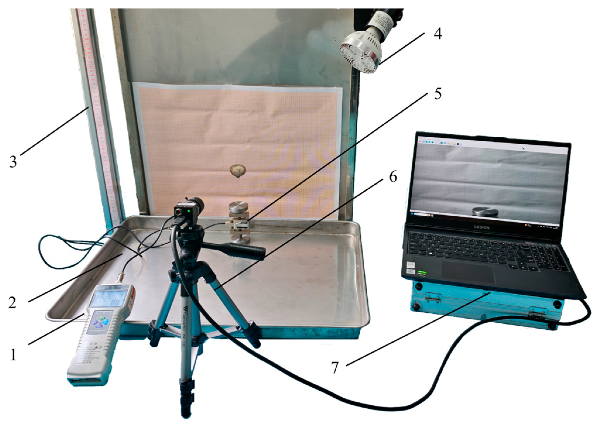
2.4.1. Free Drop Calibration Test of Clams

To investigate the impact resistance and fracture characteristics of M. veneriformis and calibrate DEM bonding parameters, we conducted free-fall experiments as illustrated in Figure 6. One hundred specimens with intact shells and uniform size were selected. The drop height gradient spanned 95–135 cm (5 cm intervals) across 9 levels, with 10 specimens per height group. A high-speed camera (USB3.0, YVSION, Shenzhen, China) captured the complete fracture process, while a digital force gauge (DS2-500N-XD, AILIGU, Shenzhen, China) and load cell (LY-103, DECENT, Shenzhen, China) recorded peak impact forces in real time. Fracture counts were systematically recorded, with the stainless steel base cleaned after each test to ensure consistency. The minimum height causing complete shell fracture in all specimens was selected as the reference height for DEM simulations.

2.4.2. Verification Test of Hydraulic Impact Clams

To verify the accuracy of the discrete element model, hydraulic impact tests on M. veneriformis were conducted (Figure 7). A high-pressure washer (Model 3600DF, ZHEXING, Taizhou, China) was used as the pressure source and fitted with a cylindrical contraction nozzle. The test conditions were nozzle inlet pressure of 5–30 MPa, outlet pressure of 0.1 MPa, saturated vapor pressure of water at room temperature of 3540 Pa, and the Realizable k–ε turbulence model. The standoff distance was 80 mm, and the jet angle was 60° relative to the horizontal. A point-fixed pulsed jet was applied, with each impact lasting 5 s. The corresponding numerical tests employed a CFD–DEM coupling approach, with geometry and operating conditions consistent with the physical experiments.

3. Results and Discussion

3.1. Microscopic Morphology Test Analysis and Simulation for Basic Parameter Determination

3.1.1. Micro-Morphology Test Results and Analysis

Mollusk shells consist of 95–99 wt.% calcium carbonate, 1–5 wt.% protein matrix, and trace water, formed through biomineralization processes [11]. The exceptional strength and toughness of mollusk shells, often surpassing engineered ceramics, have motivated extensive research into their material and structural characteristics for bioinspired design and biomimetic material development [39,40]. M. veneriformis shells exhibit a calcium carbonate composition with aragonite crystallography, featuring a cross-sectional architecture of periostracum, prismatic, and nacreous layers, characterized by a crossed lamellar microstructure. Similar to Ruditapes philippinarum [16] and Saxidomus purpuratus [41], these layers demonstrate microhardness values of 273 HV, 240 HV, and 300 HV, respectively. The mean flexural and compressive strengths reach 110.2 MPa and 80.1 MPa, respectively [42]. Most mechanical studies test shell fragments, with limited reports on whole-shell strength [43], and predominantly focus on cross-sectional structures. However, systematic investigations of surface microstructures remain scarce, particularly regarding regional morphological variations and their functional implications.
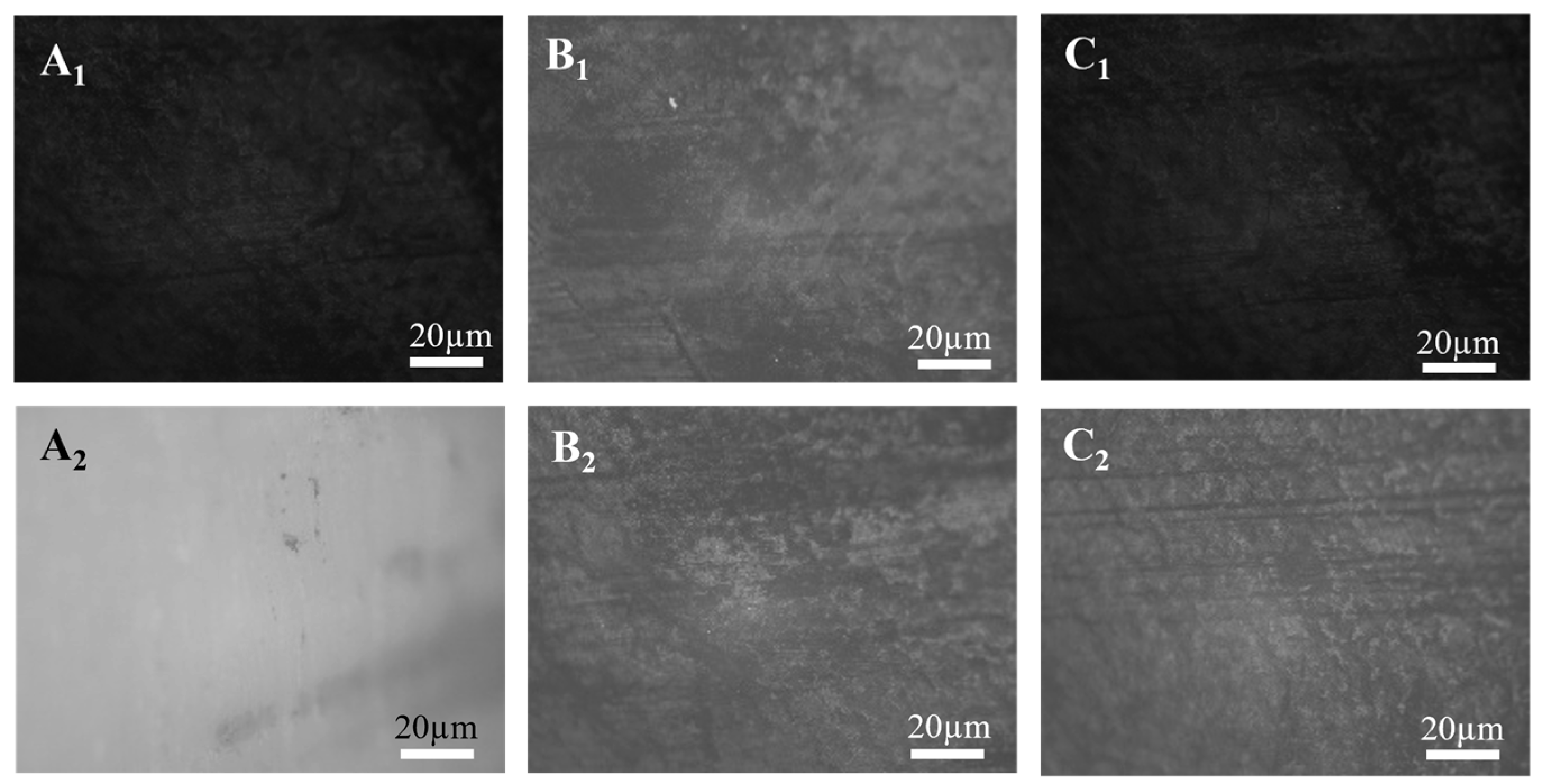
Figure 8 reveals the microstructural topography of distinct M. veneriformis shell regions, reflecting their stratigraphic distribution and biomineral deposition characteristics. Zone A1 exhibits dark-gray tonality with low light contrast, featuring a rough yet dense surface. It demonstrates relatively uniform texture without distinct laminar boundaries. Zone B1 shows significant grayscale variation, with pronounced striated and quasi-stratified structures at the central area. Obliquely or cross-aligned striations exhibit strong intergranular contrast, accompanied by occasional micro-fractures or exfoliation features. Zone C1 displays homogeneous dark coloration with blurred yet refined texture. The surface appears isotropic with high planarity, showing only faint laminar patterns. Zones A2, B2, and C2 represent microstructural alterations after 0.3mm polishing, exposing deeper lamellar architectures that elucidate key information about layer organization, interface morphology, and tissue homogeneity. Zone A2 presents lighter background grayscale with uniform structure. The polished surface maintains partial smoothness with blurred edges, indicating incomplete penetration through the outer mineralized layer. Zone B2 demonstrates enhanced texturing with regular striations or undulating patterns. Complex grayscale variations reveal multi-layered interfaces and orientation alignments. Zone C2 exhibits distinct lamellar organization with well-defined, thin interlayer boundaries. Perpendicular to growth lines: Zone A functions as impact-resistant armor; Zone B provides structural connectivity and energy dissipation; Zone C offers crack-resistant flexibility through energy absorption. This unique functionality in Zone C originates from the nacreous layer’s crack deflection mechanism [44]. Under external loading, prismatic layer fracturing dissipates stress to protect soft tissues, while plastic deformation in flexible interfacial layers provides crack-arresting energy absorption [13].
Microstructural characterization reveals pronounced anisotropic architecture in M. veneriformis shells, providing critical evidence for parameterizing the DEM Bonding V2 model. The anisotropic nature necessitates defining directional variations in normal/tangential stiffness per unit area for shell regions, while isotropic flesh domains require nullification of directional parameters to maintain physical fidelity. Furthermore, microtopographic analysis enhances current understanding of fracture resistance mechanisms, offering novel insights for mitigating shell damage during aquaculture operations.

3.1.2. Determination of Simulation Basic Parameters

Following the methodology detailed in Section 2.2, we conducted systematic measurements of the critical mechanical properties of M. veneriformis. Integrating data from references [6,7,18,25,32] with our prior research, Table 2 presents the definitive intrinsic and contact parameters for DEM modeling of M. veneriformis.

3.2. Calibration Test Results and Bonding Parameter Analysis

3.2.1. Results of Drop Test

The multi-height free-fall test results of M. veneriformis are presented in Table 3. As drop height increased from 95 cm to 130 cm, the fracture rate showed a fluctuating upward trend without strict linearity. The clams underwent free-fall under gravity, with collision against the stainless steel base causing directional reversal. Energy dissipation during inelastic collision progressively reduced rebound heights. The 100% fracture rate at ≥130 cm established this height as the critical complete fracture threshold, thus selected for parameter calibration. The maximum crushing impact force Fexp value at 130 cm is 3.5 N, the maximum is 6.1 N, and the average is 4.67 N.
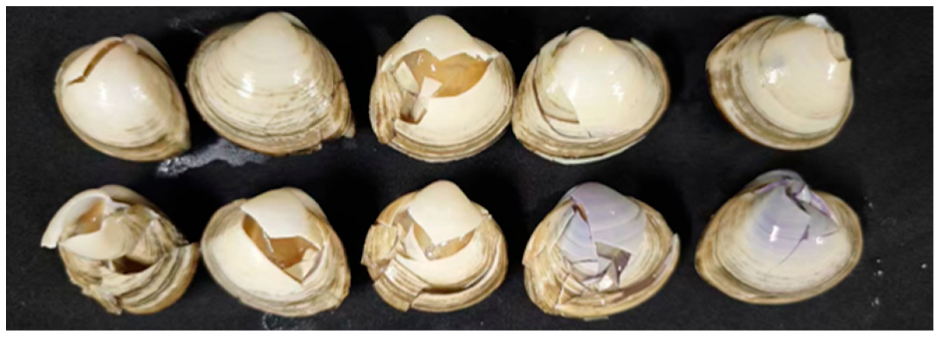
Figure 9 displays representative fracture patterns from drop tests. Mondal et al. [5] divided shells into four asymmetric zones for damage distribution analysis. Vasconcelos et al. [15] adopted a quadrant system to identify high-risk fracture zones during harvesting. Following reference [43], we developed a simplified fracture map dividing M. veneriformis into three regions (anterior, dorsal margin, posterior), with all 54 fractured specimens showing crack propagation from load points (Figure 10). Solid lines denote obligatory fracture paths, while dashed lines indicate optional crack propagations.

3.2.2. Screening Analysis of Significant Factors

The bonding parameters were calibrated and optimized through Plackett–Burman screening, steepest ascent method, and Box–Behnken response surface methodology. As an efficient two-level fractional factorial design, Plackett–Burman testing enables rapid screening of significant variables with minimal experimental runs by identifying key influencing factors [45]. Peak impact force (Fexp) served as the target response variable for bonding parameter calibration. The minimal relative error (e) between simulated and experimental peak impact forces was employed as the calibration metric. Smaller relative errors indicate better correspondence between the model’s mechanical behavior and actual M. veneriformis responses. The relative error is calculated as:
e = F exp F s i m F exp × 100 %
where e represents the relative error (%), Fexp represents the maximum impact force of actual test (N), Fsim represents the maximum impact force of simulation test (N).
The Plackett–Burman experimental design was implemented using Design-Expert 13, with bonding parameters from Table 1 serving as simulation inputs. Parameter ranges were coded as high (+1) and low (−1) levels, with simulated peak impact force as the response variable to identify statistically significant parameters. Table 4 presents the Plackett–Burman results, with ANOVA elucidating each parameter’s significance on Fexp. The analysis revealed that factors X1, X3, X6, and X7 significantly affected Fexp (p < 0.01), while other parameters showed negligible effects. Consequently, subsequent steepest ascent and Box–Behnken tests focused on optimizing these four critical parameters, with non-significant factors fixed at mid-level values. The specific settings are X2 = 3 × 10¹⁵, X4 = 2.2 × 10⁸, X5 = 4.55 × 1012 and X8 = 4.55 × 10⁷.
Building upon the Plackett–Burman results, steepest ascent experiments were conducted for the significant parameters. 4.73 N. As presented in Table 5, the steepest ascent tests yielded peak impact forces of 4.20 N (Group 1) and 4.73 N (Group 3). Experimental measurements confirmed the actual peak force resided between Groups 1–3, with Group 2 demonstrating significantly lower relative error. Consequently, the parameter ranges from Groups 1–3 were coded as low (−1), medium (0), and high (+1) levels for Box–Behnken optimization, establishing this as the optimal parameter space.
A Box–Behnken experimental design was implemented using X1, X3, X6, and X7 as test factors. Both peak impact force and relative error were employed as response variables to determine the optimal parameter combination. The Box–Behnken test results are detailed in Table 6.
Regression analysis was performed on the Box–Behnken experimental results. The analysis yielded a second-order response surface model with X1, X3, X7, and X8 as independent variables and simulated peak impact force as the response:
F = 3.37594 + 0.098 X 1 + 0.0425 X 3 + 0.31 X 6 + 0.036 X 7 0.033 X 1 X 3 0.085 X 1 X 6 + 0.00225 X 1 X 7 0.052 X 3 X 6 + 0.17 X 3 X 7 0.057 X 6 X 7 0.056 X 1 2 0.091 X 3 2 0.27 X 6 2 0.044 X 7 2
The ANOVA of the regression model demonstrated extremely high significance (p < 0.0001), with detailed results presented in Supplementary Materials, confirming the model’s statistical validity for predicting peak impact force. With R2 = 0.9600 and adjusted Radj2 = 0.9134 approaching unity, the model exhibits excellent agreement with experimental observations. The predicted RPred2 (0.9134) showed minimal difference (<0.2) from the adjusted Radj2, indicating robust predictive capability. Factor X6 exerted extremely significant influence (p < 0.0001), while X1 and X7 were significant, and X3 was non-significant. The quadratic term X62 showed extreme significance (p < 0.0001), whereas other interaction terms were non-significant. Compared with single-layer bonded models (water chestnut [36], garlic seed [46]) where significance concentrated on single stiffness/stress parameters, bilayer structures like potato [27] exhibited hierarchical significance. Although parameter significance showed similarities between M. veneriformis and potato bilayer models, their fracture patterns differed substantially. M. veneriformis displayed outside-in fracture: shell cracking preceded soft tissue damage, with cracks propagating inward. In contrast, potatoes failed via inside-out mechanisms, where internal flesh plasticization triggered periderm fracture. This divergence stems from distinct material architectures: rigid shells dominate clam failure, whereas potato damage initiates from soft tissue yielding.
The anisotropic stiffness ratios adopted in the DEM model are consistent with the observed microstructural organization of the M. veneriformis shell. SEM images revealed that the outer layer exhibits a crossed lamellar structure, while the inner layer is dominated by aragonitic nacre arranged parallel to the surface. This layered organization enhances stiffness in the tangential direction and reduces it in the normal direction. Accordingly, the normal/tangential stiffness ratios assigned to the shell–shell and shell–flesh contacts were adjusted to reflect this anisotropy, with higher tangential stiffness values corresponding to the lamellar alignment.

3.3. Parameter Optimization and Verification Analysis

3.3.1. Optimal Parameters and Verification

Using 4.67N peak impact force as the optimization target, the optimal bonding parameters were determined as flesh–flesh normal/tangential stiffness (X1) = 3.64 × 10¹¹ N/m3, shell–flesh normal/tangential stiffness (X3) = 1.48 × 10¹³ N/m3, shell–shell tangential stiffness (X6) = 3.23 × 10¹² N/m3, shell–shell normal strength (X7) = 8.35 × 10⁶ Pa.
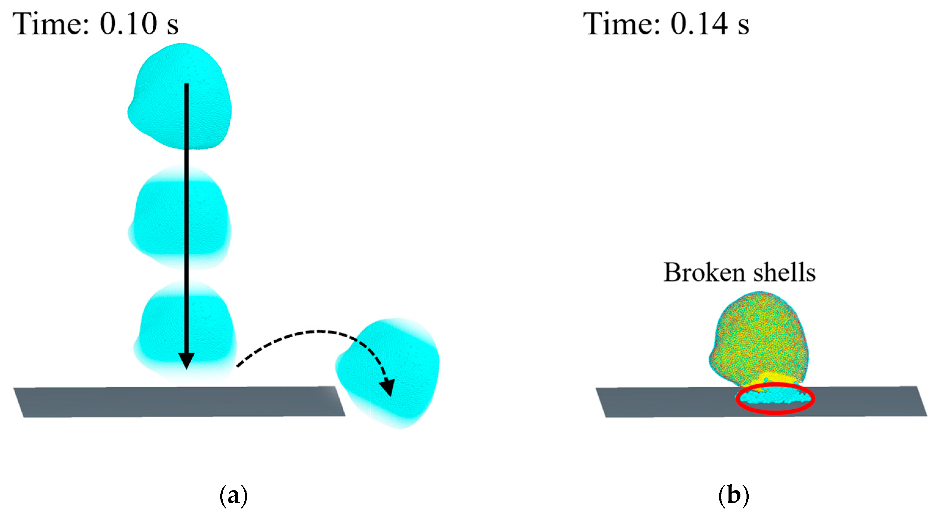
As shown in Figure 11, the drop test simulation was conducted using the optimized parameter set. Results demonstrated a simulated peak impact force of 4.90 N, with 4.89% relative error versus experimental data, indicating excellent agreement between simulation and measurements. This validates the accuracy and reliability of the M. veneriformis DEM model parameters, confirming its capability to simulate impact-induced fracture processes.

3.3.2. Hydraulic Impact Verification Results

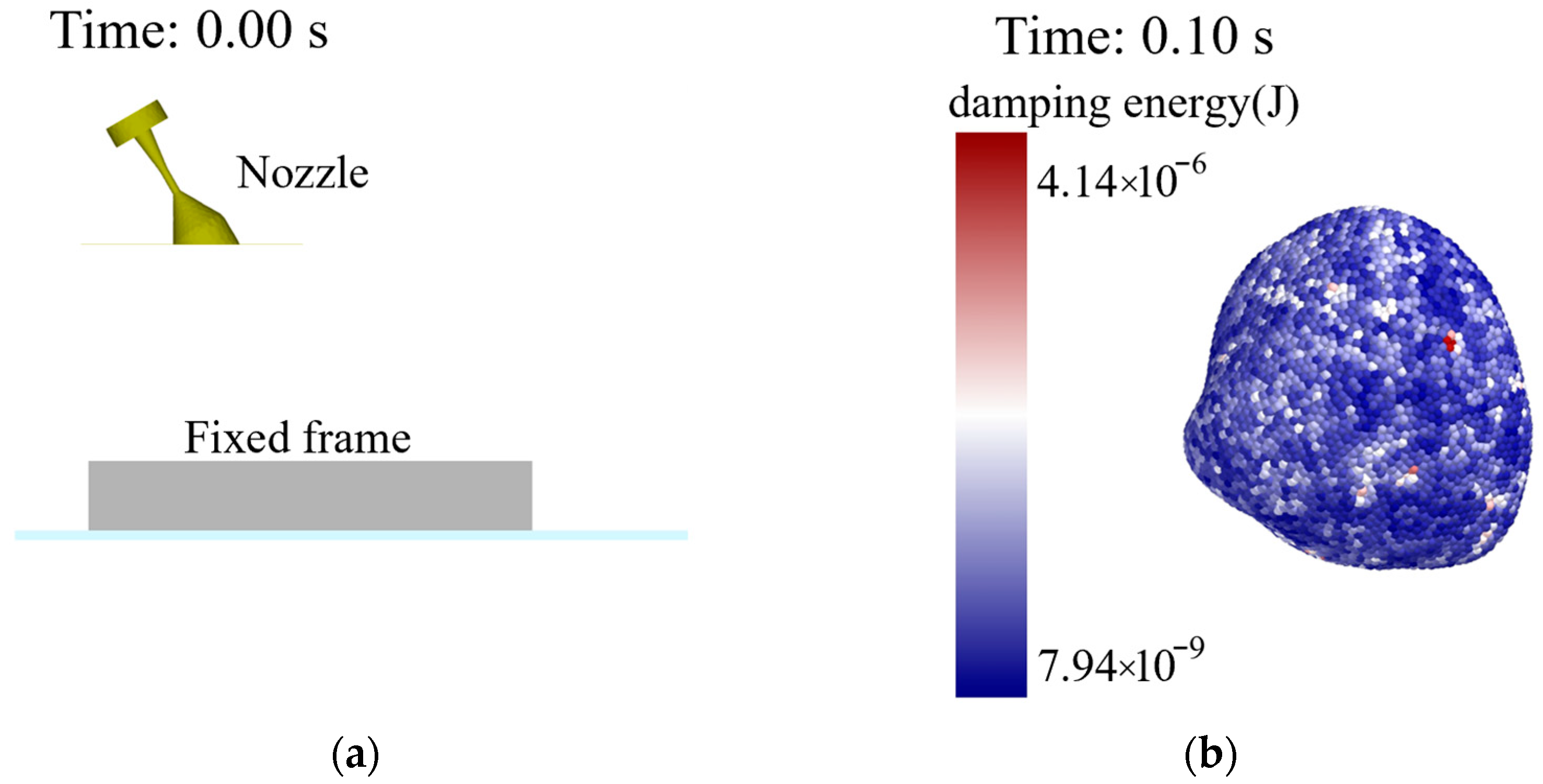
A combined experimental–numerical approach was employed to systematically investigate the mechanical response of M. veneriformis under hydraulic impact loading. Experimental results confirmed shell integrity across all tested operational parameters, with zero fracture occurrences. The developed CFD–DEM coupled model accurately replicated impact dynamics (Figure 12), demonstrating perfect consistency with experimental observations under identical conditions. This agreement not only validates the model’s reliability but crucially establishes the technical feasibility of hydraulic harvesting for M. veneriformis, proving that properly configured hydraulic systems can achieve efficient operation while preserving shell integrity, thus providing theoretical foundations for low-impact harvesting equipment development. A consolidated discussion on the model’s applicability, limitations, and future work is provided in Section 3.4.

3.4. Applicability, Limitations, and Future Work

The calibrated dual-layer DEM of M. veneriformis reproduces drop test responses and hydraulic impact behavior within the measured size range and test conditions. It supports representative mechanized harvesting modes—screen–brush vibratory harvesting via DEM–MBD coupling and hydraulic harvesting via CFD–DEM coupling—enabling time-resolved visualization of shell–tool interactions and relating damage to equipment parameters for low-damage design. The framework has been used to assist structural optimization of a vibrating digging shovel and is transferable to fragile bivalves such as R. philippinarum. Validation in this revision emphasizes peak force; standardized statistics for rebound height and crack length were not consistently acquired across replicates. Size effects (e.g., ±10% geometry scaling) and potential age-/environment-dependent variability in shell properties (thickness, mineral fraction, interfacial strength) are not explicitly parameterized. Hydraulic loading is simplified (steady inlet pressure; cavitation/transient jet structures not fully resolved). Soil–clam interactions are represented by calibrated contact laws without a substrate–bivalve aggregate model, and coarse-graining/time-step sensitivity and parameter uncertainty/identifiability remain to be quantified.
We will (1) introduce covariate-aware parameterization that links stress-/energy-based contact properties to size/age and environmental descriptors (temperature, salinity, pH) with stratified experiments; (2) extend validation to rebound height and crack length and test robustness under ±10% size variation and broader hydraulic conditions; (3) develop a substrate–bivalve aggregate model to improve shell–soil–tool fidelity; (4) perform uncertainty quantification and global sensitivity analysis to support robust equipment optimization; and (5) transfer and re-validate the model for R. philippinarum and upscale to harvester-scale simulations and field trials with standardized imaging/sensing.
The model establishes a direct mapping between harvester parameters and shell damage, enabling rapid in silico tuning for screen–brush vibratory and hydraulic harvesting to support low-damage design. Lower breakage is expected to increase saleable yield and reduce development costs, and the framework is readily extendable to other bivalve species.

4. Conclusions

In this study, we investigated shell damage during mechanized harvesting of M. veneriformis by developing a dual-layer discrete element model through microstructure analysis and parameter optimization. The main findings are:
(1)
Microscopic observation revealed that M. veneriformis shells exhibit distinct anisotropic layered structures, with significant differences in morphology, texture, and mechanical properties across different regions. These findings provide a structural basis for determining bonding parameters in DEM modeling while deepening the understanding of shell fracture resistance mechanisms, offering theoretical support for solving practical shell damage problems.
(2)
A dual-layer DEM model of shell and flesh was developed based on the Hertz–Mindlin with Bonding V2 contact model. Through free-fall tests and experimental designs (Plackett–Burman screening, steepest ascent method, and Box–Behnken optimization), four key bonding parameters were identified and optimized: flesh–flesh normal/tangential stiffness (X1) = 3.64 × 10¹¹ N/m3, shell–flesh normal/tangential stiffness (X3) = 1.48 × 10¹³ N/m3, shell–shell tangential stiffness (X6) = 3.23 × 10¹² N/m3, and shell–shell normal strength (X7) = 8.35 × 10⁶ Pa.
(3)
Under optimal parameters, the relative error of the maximum impact force between simulated and actual drop tests was 4.89%. In hydraulic impact tests, the CFD–DEM simulations agreed well with experiments and showed no shell fractures, confirming model accuracy under complex loading and demonstrating the feasibility of hydraulic harvesting for preserving shellfish integrity. The established model provides a reliable tool for optimizing M. veneriformis harvesting equipment, is transferable to fragile bivalves such as R. philippinarum, and supports simulation of representative mechanized modes to relate shell damage to equipment parameters and guide low-damage design; future integration of substrate–bivalve aggregate models will further strengthen engineering applicability.

Supplementary Materials

The following supporting information can be downloaded at: https://www.mdpi.com/article/10.3390/fishes10090429/s1, Figure S1: Experimental Setup for 3D Scanning and Modeling of M. veneriformis; Figure S2: Bland–Altman analysis of agreement between experimental and simulated force; Code S1: Resolve overlaps; Code S2: Develop a model.

Author Contributions

Conceptualization, B.X. and G.M.; methodology, B.X. and G.M.; software, B.X. and Y.Y.; validation, H.L., G.C., and H.W.; formal analysis, Y.Y. and J.Z.; investigation, Y.C., F.G., and Z.L.; resources, G.Z. and X.L.; data curation, G.M.; writing—original draft preparation, B.X.; writing—review and editing, G.M. and B.X.; visualization, Y.Y.; supervision, G.M.; project administration, H.Z. and Q.Z.; funding acquisition, G.M. All authors have read and agreed to the published version of the manuscript.

Funding

This research was funded by the National Key R&D Program of China, grant number 2023YFD2400800. The Basic Scientific Research Program of Liaoning Provincial Education Department, Grant Number LJ232410158048. Liaoning Provincial Undergraduate Colleges and Universities Basic Scientific Research Operational Fees Program, Grant number 2024JBPTZ002. Liaoning Provincial Science and Technology Plan Joint Program, grant number 2024JH2/102600082. Dalian Science and Technology Innovation Fund, Grant number 2024JJ13GX039.

Institutional Review Board Statement

Not applicable.

Data Availability Statement

Data are contained within the article.

Acknowledgments

The authors gratefully acknowledge Licui Xu from University of Science and Technology Liaoning for her important contributions to the microscopic characterization. The authors would also like to express special gratitude to the editors and reviewers for their insightful comments that enhanced the manuscript.

Conflicts of Interest

The authors declare no conflicts of interest.

References

  1. Bureau of Fisheries, Ministry of Agriculture and Rural Affairs. China Fishery Statistical Yearbook 2024; China Agriculture Press: Beijing, China, 2024.
  2. Cheng, J.; Wang, H.; Sun, D. An Overview of Tropomyosin as an Important Seafood Allergen: Structure, Cross-reactivity, Epitopes, Allergenicity, and Processing Modifications. Comp. Rev. Food Sci. Food Saf. 2022, 21, 127–147. [Google Scholar] [CrossRef]
  3. Zhang, T.; Hua, Y.; Zhou, C.; Xiong, Y.; Pan, D.; Liu, Z.; Dang, Y. Umami Peptides Screened Based on Peptidomics and Virtual Screening from Ruditapes Philippinarum and Mactra Veneriformis Clams. Food Chem. 2022, 394, 133504. [Google Scholar] [CrossRef]
  4. Li, F.-J.; He, X.-R.; Li, D.-X.; Yang, Y.; Kang, S.; Liu, Q.-M.; Luo, L.-Z.; Chen, G.-X.; Liu, G.-M. Effect of Maillard Reaction on the Allergenicity of Crude Extract of Mactra Quadrangularis. Food Res. Int. 2025, 200, 115473. [Google Scholar] [CrossRef] [PubMed]
  5. Mondal, S.; Bardhan, S.; Mallick, S.; Roy, A. Repair Scars on Mactra Violacea from the Eastern Coast of India: A New Classification and a Model for Describing Shell Breakage on Bivalves. Palaeontol. Electron. 2014, 17, 1–13. [Google Scholar] [CrossRef]
  6. Li, H.; Mu, G.; Li, X.; Wu, H.; Bin, X.; Liu, F.; Sun, Z.; Zhang, Q.; Zhang, H.; Xin, M.; et al. Design and Testing of the Clam Vibration Harvester’s V-Shaped Double-Spiral Harvesting Roller Brush Based on DEM-MBD. Aquac. Eng. 2025, 111, 102582. [Google Scholar] [CrossRef]
  7. Li, H.; Zhang, G.; Liu, F.; Li, X.; Wang, Y.; Mu, G. Design and Testing of Mudflat Shellfish Vibrating Harvester Based on DEM-MBD Simulation. Trans. Chin. Soc. Agric. Mach. 2024, 55, 361–370. [Google Scholar]
  8. Kaplan, D.L. Mollusc Shell Structures: Novel Design Strategies for Synthetic Materials. Curr. Opin. Solid State Mater. Sci. 1998, 3, 232–236. [Google Scholar] [CrossRef]
  9. Zhang, P.; Tang, J.; Tang, Q.; Zhang, M.; Shen, L.; Tian, W.; Zhang, Y.; Sun, Z. Shell Powder as a Novel Bio-Filler for Thermal Insulation Coatings. Chin. J. Chem. Eng. 2019, 27, 452–458. [Google Scholar] [CrossRef]
  10. Panigrahi, A.; Jena, H.; Surekha, B. Effect of Clams Shell in Impact Properties of Jute Epoxy Composite. Mater. Today Proc. 2018, 5, 19997–20001. [Google Scholar] [CrossRef]
  11. Li, T.; Zeng, K. Nano-Hierarchical Structure and Electromechanical Coupling Properties of Clamshell. J. Struct. Biol. 2012, 180, 73–83. [Google Scholar] [CrossRef]
  12. Wang, L.C.; Di, L.Q.; Liu, R.; Wu, H. Characterizations and Microsphere Formulation of Polysaccharide from the Marine Clam (Mactra Veneriformis). Carbohydr. Polym. 2013, 92, 106–113. [Google Scholar] [CrossRef] [PubMed]
  13. Ma, Y.H.; Chai, X.W.; Yan, Z.F.; Chen, D.H.; Man, J. Clam Shell Compression Characteristics and Bond Strength. Adv. Mater. Res. 2012, 472–475, 2554–2557. [Google Scholar] [CrossRef]
  14. Fakayode, O.A. Size-Based Physical Properties of Hard-Shell Clam (Mercenaria mercenaria) Shell Relevant to the Design of Mechanical Processing Equipment. Aquac. Eng. 2020, 89, 102056. [Google Scholar] [CrossRef]
  15. Vasconcelos, P.; Morgado-André, A.; Morgado-André, C.; Gaspar, M.B. Shell Strength and Fishing Damage to the Smooth Clam (Callista Chione): Simulating Impacts Caused by Bivalve Dredging. ICES J. Mar. Sci. 2011, 68, 32–42. [Google Scholar] [CrossRef]
  16. Mu, G.; Duan, F.; Zhang, G.; Li, X.; Ding, X.; Zhang, L. Microstructure and Mechanical Property of Ruditapes Philippinarum Shell. J. Mech. Behav. Biomed. Mater. 2018, 85, 209–217. [Google Scholar] [CrossRef]
  17. Giordano, V.; Castagnoli, A.; Pecorini, I.; Chiarello, F. Identifying Technologies in Circular Economy Paradigm through Text Mining on Scientific Literature. PLoS ONE 2024, 19, e0312709. [Google Scholar] [CrossRef]
  18. Li, H.; Zhang, G.; Li, X.; Zhang, H.; Zhang, Q.; Liu, W.; Mu, G. Calibration of the Discrete Element Method Parameters in Living Juvenile Manila Clam (Ruditapes Philippinarum) and Seeding Verification. AgriEngineering 2021, 3, 894–906. [Google Scholar] [CrossRef]
  19. Zhang, Y.; Gai, G.; Zong, W.; Chen, P.; Wang, F.; Wang, X. Crushing Mechanism of Walnut under Extrusion-Shear Load Based on FDEM. Trans. Chin. Soc. Agric. Mach. 2025, 56, 291–300. [Google Scholar]
  20. Tang, H.; Zhu, G.; Wang, Z.; Xu, W.; Xu, C.; Wang, J. Prediction Method for Maize Kernel Impact Breakage Based on High-Speed Camera and FEM. Powder Technol. 2024, 444, 120002. [Google Scholar] [CrossRef]
  21. Tang, H.; Zhu, G.; Sun, Z.; Xu, C.; Wang, J. Impact Damage Evolution Rules of Maize Kernel Based on FEM. Biosyst. Eng. 2024, 247, 162–174. [Google Scholar] [CrossRef]
  22. Guan, X.; Li, T.; Zhou, F. Determination of Bruise Susceptibility of Fresh Corn to Impact Load by Means of Finite Element Method Simulation. Postharvest Biol. Technol. 2023, 198, 112227. [Google Scholar] [CrossRef]
  23. Hou, J.; Park, B.; Li, C.; Wang, X. A Multiscale Computation Study on Bruise Susceptibility of Blueberries from Mechanical Impact. Postharvest Biol. Technol. 2024, 208, 112660. [Google Scholar] [CrossRef]
  24. Zhang, G.; Li, Z.; Liu, W.; Zhang, Q.; Chen, L.; Pei, L.; Liu, H. Finite Element Simulation and Experiment of Impact Damage of Water Chestnuts. Trans. Chin. Soc. Agric. Eng. 2025, 41, 40–49. [Google Scholar]
  25. Lou, Y.; Zhang, G.; Li, X.; Zhang, Q.; Zhang, H.; Zhao, J.; Li, H.; Wu, H.; Ye, Z.; Zhang, Z.; et al. Experiment and Calibration of Contact Parameters of Mactra Veneriformis Based on DEM. Comput. Part. Mech. 2025, 12, 313–326. [Google Scholar] [CrossRef]
  26. Kafashan, J.; Wiacek, J.; Ramon, H.; Mouazen, A.M. Modelling and Simulation of Fruit Drop Tests by Discrete Element Method. Biosyst. Eng. 2021, 212, 228–240. [Google Scholar] [CrossRef]
  27. Gai, X.; Xie, S.; Deng, W.; Lu, K.; Ji, X. Construction and Parameter Calibration of Potato Double-layer Flexible Bonding Model Based on Discrete-element Method. J. Food Process Eng. 2024, 47, e14602. [Google Scholar] [CrossRef]
  28. Liu, W.; Zhang, G.; Yong, Z.; Liu, H.; Tang, N.; Kang, Q.; Zhao, Z. Establishment of Discrete Element Flexible Model of the Tiller Taro Plant and Clamping and Pulling Experiment. Front. Plant Sci. 2022, 13, 1019017. [Google Scholar] [CrossRef] [PubMed]
  29. Zhu, H.; He, X.; Shang, S.; Zhao, Z.; Wang, H.; Tan, Y.; Li, C.; Wang, D. Evaluation of Soil-Cutting and Plant-Crushing Performance of Rotary Blades with Double-Eccentric Circular-Edge Curve for Harvesting Cyperus Esculentus. Agriculture 2022, 12, 862. [Google Scholar] [CrossRef]
  30. Zhao, Z.; Wang, D.; Shang, S.; Guo, P.; Gao, Z.; Xia, C.; Yan, H.; Hou, J. Design and Test of a Dual-Axis Layered Rotary Tillage Stubble Exterminator in Saline-Alkali Land Based on Discrete Elements. Int. J. Agric. Biol. Eng. 2024, 17, 163–175. [Google Scholar] [CrossRef]
  31. Zhang, J.; Wang, J.; Du, D.; Long, S.; Wang, Y.; Han, C.; Xu, Y. Optimization and Validation of Root-Cutting Device for Chinese Cabbage Harvester Based on Discrete Element Method. Comput. Electron. Agric. 2023, 214, 108314. [Google Scholar] [CrossRef]
  32. Luan, Y. Discrete Element Simulation Parameter Calibration for Smart Shellfish Seeding Devices. J. Intell. Agric. Mech. 2025, 6, 69–78. [Google Scholar]
  33. Zeng, H.; Xu, W.; Zang, M.; Yang, P. Calibration of DEM-FEM Model Parameters for Traction Performance Analysis of an off-Road Tire on Gravel Terrain. Powder Technol. 2020, 362, 350–361. [Google Scholar] [CrossRef]
  34. Chen, X.; Wang, L.G.; Morrissey, J.P.; Ooi, J.Y. DEM Simulations of Agglomerates Impact Breakage Using Timoshenko Beam Bond Model. Granul. Matter 2022, 24, 74. [Google Scholar] [CrossRef]
  35. Zhang, S.; Zhang, R.; Cao, Q.; Zhang, Y.; Fu, J.; Wen, X.; Yuan, H. A Calibration Method for Contact Parameters of Agricultural Particle Mixtures Inspired by the Brazil Nut Effect (BNE): The Case of Tiger Nut Tuber-Stem-Soil Mixture. Comput. Electron. Agric. 2023, 212, 108112. [Google Scholar] [CrossRef]
  36. Zhang, G.; Chen, L.; Liu, H.; Dong, Z.; Zhang, H.; Zhou, Y. Calibration and Experiments of the Discrete Element Simulation Parameters for Water Chestnut. Trans. Chin. Soc. Agric. Eng. 2022, 38, 41–50. [Google Scholar]
  37. Liu, F.; Tang, H.; Shahin, M.A.; Zhao, H.; Karrech, A.; Zhu, F.; Zhou, H. Multiscale Simulation Study for Mechanical Characteristics of Coral Sand Influenced by Particle Breakage. Powder Technol. 2025, 449, 120387. [Google Scholar] [CrossRef]
  38. Chen, T.; Yi, S.; Li, Y.; Tao, G.; Qu, S.; Li, R. Establishment of Discrete Element Model and Parameter Calibration of Alfalfa Stem in Budding Stage. Trans. Chin. Soc. Agric. Mach. 2023, 54, 91–100. [Google Scholar]
  39. Zhou, B.L. Bio-Inspired Study of Structural Materials. Mater. Sci. Eng. C 2000, 11, 13–18. [Google Scholar] [CrossRef]
  40. Liang, Y.; Zhao, J.; Wu, C. The Micro/Nanostructure Characteristics and the Mechanical Properties of Hemifusus Tuba Conch Shell. J. Bionic Eng. 2010, 7, 307–313. [Google Scholar] [CrossRef]
  41. Yang, W.; Kashani, N.; Li, X.-W.; Zhang, G.-P.; Meyers, M.A. Structural Characterization and Mechanical Behavior of a Bivalve Shell (Saxidomus Purpuratus). Mater. Sci. Eng. C 2011, 31, 724–729. [Google Scholar] [CrossRef]
  42. Liang, Y.; Zhao, Q.; Li, X.; Zhang, Z.; Ren, L. Study of the Microstructure and Mechanical Properties of White Clam Shell. Micron 2016, 87, 10–17. [Google Scholar] [CrossRef]
  43. Zuschin, M.; Stanton, R.J. Experimental Measurement of Shell Strength and Its Taphonomic Interpretation. Palaios 2001, 16, 161–170. [Google Scholar] [CrossRef]
  44. Menig, R.; Meyers, M.H.; Meyers, M.A.; Vecchio, K.S. Quasi-Static and Dynamic Mechanical Response of Haliotis Rufescens (Abalone) Shells. Acta Mater. 2000, 48, 2383–2398. [Google Scholar] [CrossRef]
  45. Zhou, J.; Yu, X.; Ding, C.; Wang, Z.; Zhou, Q.; Pao, H.; Cai, W. Optimization of Phenol Degradation by Candida Tropicalis Z-04 Using Plackett-Burman Design and Response Surface Methodology. J. Environ. Sci. 2011, 23, 22–30. [Google Scholar] [CrossRef] [PubMed]
  46. Li, H.; Meng, Y.; Qi, X.; Wang, Y.; Li, Y.; Li, M. Discrete Element Modelling Method and Parameter Calibration of Garlic Species Based on Bonding V2 Model. Trans. Chin. Soc. Agric. Mach. 2025, 56, 150–157. [Google Scholar]
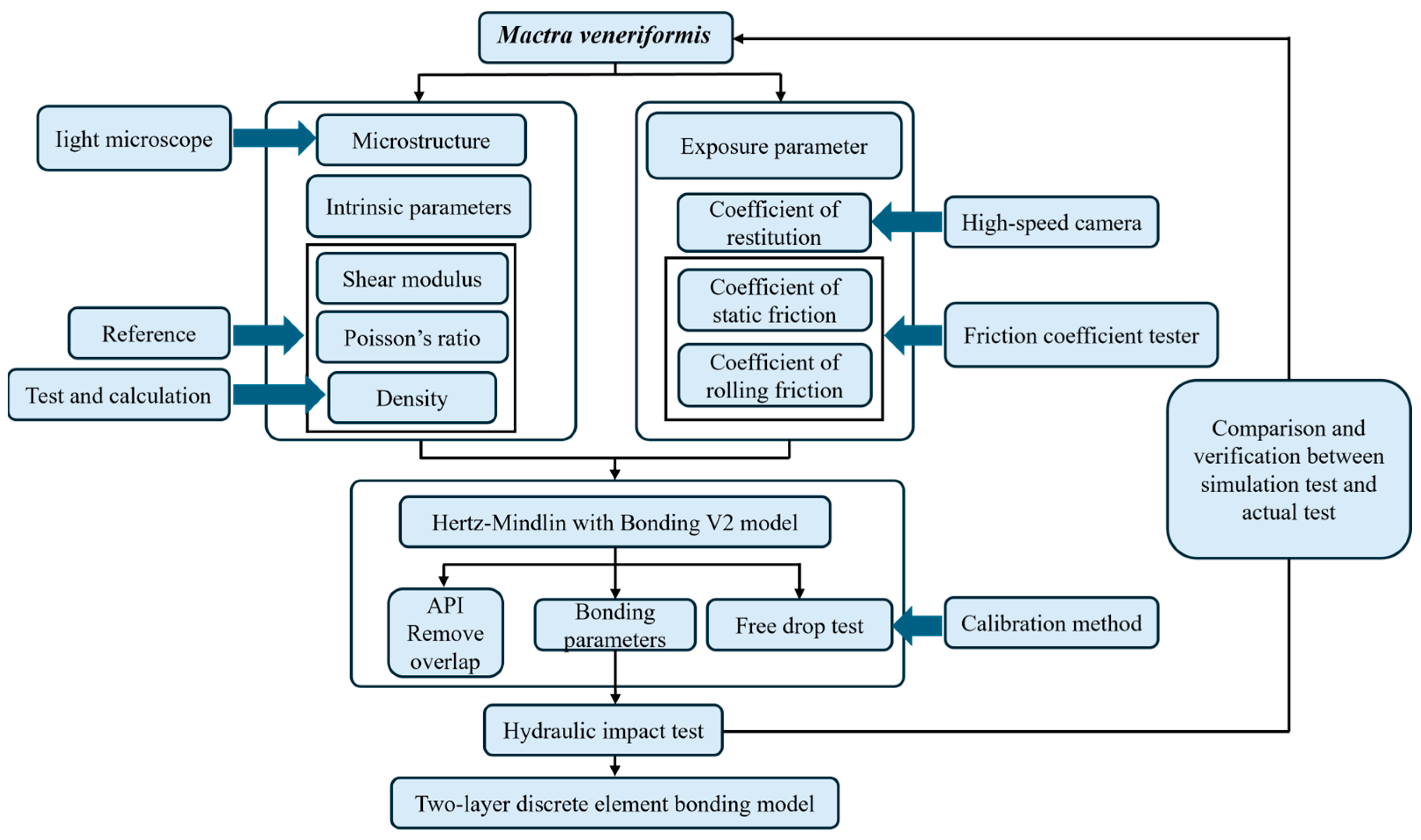
Figure 1. Total process of test method.
Fishes 10 00429 g001
Figure 2. The shape and size of four-horned clams.
Fishes 10 00429 g002
Figure 3. Micro-morphology test of clam shell.
Fishes 10 00429 g003
Figure 4. Determination of related friction coefficient. 1. Clam flesh and shell samples. 2. Sample loading platform. 3. Force sensor. 4. Loading head. 5. Printer interface module. 6. Control and display panel 7. Power switch.
Fishes 10 00429 g004
Figure 5. Determination of related friction coefficient.
Fishes 10 00429 g005
Figure 6. Free drop test diagram of clams. 1. Digital force gauge. 2. Stainless steel base plate. 3. Height-measuring scale. 4. LED auxiliary lighting. 5. Load cell. 6. High-speed camera. 7. Data acquisition laptop.
Fishes 10 00429 g006
Figure 7. Hydraulic impact clam test. 1. Nozzle. 2. High-pressure cleaner. 3. Bucket. 4. Custom-built holder. 5. Clam.
Fishes 10 00429 g007
Figure 8. Micro-morphology of clam shell.
Fishes 10 00429 g008
Figure 9. Physical map of a portion of the broken clams.
Fishes 10 00429 g009
Figure 10. Simplified diagram of clam crushing.
Fishes 10 00429 g010
Figure 11. Clam drop simulation test. (a) Free-falling process of clams. (b) Clams impact stainless steel bottom plate.
Fishes 10 00429 g011
Figure 12. CFD simulation of clam under fluid impact. (a) Simulation process. (b) Clams after hydraulic impact.
Fishes 10 00429 g012
Table 1. The range of bonding parameters of clam double-layer bonding model.
LevelParameterValue Ranges
X1Flesh–flesh normal (tangential) stiffness per unit area (N·m3)1 × 10¹¹~1 × 1012
X2Flesh–flesh normal (tangential) strength (Pa)1 × 10¹⁵~5 × 1015
X3Shell–flesh normal (tangential) stiffness per unit area (N·m3)4 × 10¹²~4 × 1013
X4Shell–flesh normal (tangential) strength (Pa)4 × 10⁷~4 × 108
X5Shell–shell normal stiffness per unit area (N·m3)1 × 10¹¹~9 × 1012
X6Shell–shell tangential stiffness per unit area (N·m3)1 × 10¹¹~9 × 1012
X7Shell–shell normal strength (Pa)1 × 10⁶~9 × 107
X8Shell–shell tangential strength (Pa)1 × 10⁶~9 × 10⁷
Table 2. Intrinsic parameters and contact parameters.
ParameterValueParameterValue
Clam shell Poisson‘s ratio0.28Shell–flesh collision recovery coefficient0.08
Clam shell density (kg·m−3)2600Shell–flesh static friction coefficient0.65
Shear modulus of clam shell (Pa)1.5 × 10⁹Shell–flesh dynamic friction coefficient0.30
Poisson‘s ratio of clam flesh0.48Flesh–flesh collision recovery coefficient0.15
Clam flesh density (kg·m−3)1050Flesh–flesh static friction coefficient0.45
Clam flesh shear modulus (Pa)2 × 10⁴Flesh–flesh dynamic friction coefficient0.30
Poisson‘s ratio of stainless steel0.30Restitution coefficient of shell–steel collision0.28
Stainless steel density (kg·m−3)7800Shell–steel static friction coefficient0.62
Stainless steel shear modulus (Pa)7.8 × 10¹²Shell–steel dynamic friction coefficient0.16
Shell–shell collision recovery coefficient0.22Restitution coefficient of flesh–steel collision0.10
Shell–shell static friction coefficient0.41Flesh–steel static friction coefficient0.35
Shell–shell dynamic friction coefficient0.23Flesh–steel dynamic friction coefficient0.2
Table 3. Drop test results for Mactra veneriformis.
No.Drop HeightFracturedIntactFracture Rate
1951910%
21005550%
31057370%
41106460%
51152820%
61204640%
71259190%
8130100100%
9135100100%
Table 4. Plackett–Burman test results.
No.X1X2X3X4X5X6X7X8Fsim (N)
11−111−11116.33
2−1−1−11−111−15.49
311−1111−1−14.73
41−1−1−11−1115.24
5−111−1111−16.15
6111−1−1−11−15.76
7−11−111−1114.37
811−1−1−11−114.89
9−1−11−111−114.42
101−1111−1−1−15.11
11−1−1−1−1−1−1−1−14.21
12−1111−1−1−114.41
Table 5. Steepest ascent test results.
No.X1X3X6X7Fsim (N)E (%)
11 × 10114 × 10121 × 10111 × 1064.2010.07
22.8 × 10111.13 × 10131.92 × 10121.92 × 1074.700.71
34.6 × 10111.86 × 10133.74 × 10123.74 × 1074.731.35
46.4 × 10112.50 × 10135.56 × 10125.56 × 1074.751.79
58.2 × 10113.32 × 10137.38 × 10127.38 × 1074.812.42
61 × 10124 × 10139 × 10129 × 1075.2411.20
Table 6. Box–Behnken test results.
No.X1X3X6X7Fsim (N)E (%)
100004.6300.85
200−1−14.07512.74
30−10−14.6540.35
4010−14.3826.17
5−100−14.3716.41
6−10104.7642.01
7100−14.6560.31
810104.5632.29
901104.5871.77
10−1−1004.3536.79
11−10−103.92515.96
1200114.6310.83
1301014.7311.31
1400004.6310.84
1501−103.96115.19
160−10−14.3097.74
17001−14.6700.01
181−1004.7481.68
1900114.7982.74
200−1104.7892.55
210−1−103.95515.31
2211004.7301.28
2300−114.2638.70
2410014.8002.78
2510−104.06512.95
26−10014.5063.52
27−11004.4684.33
Disclaimer/Publisher’s Note: The statements, opinions and data contained in all publications are solely those of the individual author(s) and contributor(s) and not of MDPI and/or the editor(s). MDPI and/or the editor(s) disclaim responsibility for any injury to people or property resulting from any ideas, methods, instructions or products referred to in the content.