Article

Design and Performance Evaluation of a Feed Distribution Device in the Small-Scale Pneumatic Conveying Feeder for Recirculating Aquaculture Systems

1
School of Engineering, Huzhou University, Huzhou 313000, China
2
Zhejiang Yulaoda Agricultural Technology Co., Ltd., Quzhou 324400, China
3
College of Advanced Agricultural Sciences, Zhejiang Wanli University, Ningbo 315101, China
*
Authors to whom correspondence should be addressed.
These authors contributed equally to this work.
Fishes 2025, 10(6), 255; https://doi.org/10.3390/fishes10060255
Submission received: 7 April 2025 / Revised: 25 May 2025 / Accepted: 27 May 2025 / Published: 29 May 2025
(This article belongs to the Section Fishery Facilities, Equipment, and Information Technology)

Abstract

Due to its good adaptability, the pneumatic conveying feeder has been widely developed and applied in recirculating aquaculture systems (RASs). Its important performances include the integrity of feed pellets and the feeding accuracy. The aim of this study was to design and evaluate a feed distribution device for a small-scale pneumatic conveying feeder. A cylindrical hopper with a feed capacity of 4 kg and a feed distribution device were designed based on theoretical calculations. The motion and force of feed pellets during the distribution process were studied using the discrete element method (DEM) simulation to evaluate the integrity of feed pellets. Additionally, to evaluate feeding accuracy, the effect of discharge disk rotational speed on single feeding quantity was studied using DEM simulations and experimental validations, as well as the effect of the proportion of feed pellets in the hopper. Results showed that the maximum force on feed pellets was 1.25 N during the distribution process. It was inferred that the feed pellets can be distributed without breaking based on their shear strength. When the rotational speed of the discharge disk was set at a maximum of 28 rpm, the relative error of single feeding quantity between simulation and actual experiments was 4.43%, and the single feeding mass was 62.74 g, suggesting an optimal speed. In addition, the average single feeding quantity ranged from 262 to 301 feed pellets at the different proportions of feed pellets in the hopper, and its coefficient of variation was 12.46%, which generally meets the distribution requirements of the small-scale feeder. This study provides a feed distribution device for a small-scale pneumatic conveying feeder and offers references for the relevant analysis of DEM simulation.
Key Contribution: A cylindrical hopper with a feed capacity of 4 kg and a feed distribution device were designed for a small-scale pneumatic conveying feeder. No feed pellet breakage was confirmed during the distribution process. The optimal discharge disk rotational speed in the feed distribution device was determined, and a negligible impact of feed pellet proportion in the hopper on the single feeding quantity was suggested, generally meeting the feeding requirements of small culture tanks in recirculating aquaculture systems.

1. Introduction

Recirculating aquaculture system (RAS) is an advanced, sustainable production model with high unit yield, full process control, and environmental safety. To facilitate the application of RAS in China, it is essential to reduce costs and improve benefits [1,2]. In RAS production, feed cost accounts for over 40%, and insufficient feeding causes slow growth of aquatic organisms, while excessive feeding leads to feed waste and water pollution [3,4,5]. In addition, the feeding frequency also affects the farmed organisms, e.g., feeding 6–8 times/day resulted in better growth performance and antioxidant capacity in white shrimp, but required more labor [6]. Due to labor shortages and increasing costs, the demand for efficient and precise automatic feeders is becoming more urgent.
Based on the method of feed pellet delivery, automatic feeders are mainly categorized into pneumatic conveying, centrifugal, and hydraulic types [7]. Among these, pneumatic conveying feeders are characterized by a low feed pellet breakage rate and a wide delivery range, making them the focus of considerable research and development [8,9]. With the rapid development of computer-aided technologies in recent years, the discrete element method (DEM) has been widely adopted in numerical simulations and has become an effective method for specifically studying particle conveying problems [10,11,12,13,14,15]. For instance, Zhao et al. simulated the process of throwing feed pellets to optimize the feeder structure using DEM simulation coupled with computational fluid dynamics (CFD), determined the optimal design parameters, and suggested that the result of the actual test was consistent with the simulation value [13]. Song et al. simulated the pneumatic conveying characteristics of shrimp feed pellets to minimize power consumption using the same method and determined the optimal inlet wind speed for adult shrimp pool to be 24 m/s, with a feeding mass flow rate of 0.54 kg/s, and the optimal inlet wind speed for juvenile shrimp pool to be 21 m/s, with a feeding mass flow rate of 0.27 kg/s [14]. Although the pneumatic conveying feeder has undergone certain developments, challenges such as poor compatibility, unstable operation, and low feeding accuracy still persist [16]. The development of various sensors and artificial intelligence technologies for diagnosing fish conditions and feeding behaviors enhances the prediction of daily feed intake, which increases the requirement for feeding accuracy [17,18]. In addition, there is a wide variety of aquaculture species in China, coupled with the varying feed specifications at different growth stages and feed characteristics from different manufacturers, and all these contribute to the complexities and difficulties in developing the feeders. Therefore, pneumatic conveying feeders that are stable in operation, compact in size, and suitable for different RAS scenarios need to be further studied [9].
In pneumatic conveying feeders, the feed distribution device is used to achieve the quantitative separation of feed pellets, and its stability and reliability play a decisive role in feeding accuracy. The motion of feed pellets is complex, involving dynamics of individual pellets, interactions between pellets, and collisions and friction between the pellets and boundaries like the hopper and conveying pipes. This potentially leads to feed pellet breakage, affecting fish ingesting behavior and water quality [19]. Halstensen et al. proposed a method of monitoring the feed pellet delivery speed by combining acoustic measurement with a multiple regression model, which was expected to reduce feed pellet breakage [20]. However, it is challenging to characterize the force and motion of feed pellets during the feeding process through experiments or tests, and real-time feedback control is also rarely implemented. Hence, it should be thoroughly considered in the developing phase to prevent feed pellet breakage. This study dealt with a small-scale pneumatic conveying feeder fixed beside a culture tank with a biomass of less than 100 kg, typically for farming broodstock or experimental RAS. A hopper and a feed distribution device targeting the expanded floating feed pellets were designed, and the distribution process was evaluated through DEM simulation with the aim of providing references for developing a small-scale feeder.

2. Materials and Methods

2.1. Physical Properties of Feed Pellet

This study focuses on the cylindrical expanded floating feed pellets of Tongwei-180-5.0. The mass was measured using an electronic Mettler Toledo balance (0.0001 g). The number of pellets was incrementally increased from 0 to 250, with 10 pellets added at a time. The mass of each group was recorded, and the average mass of a single pellet was calculated to be 0.253 g. Additionally, bench tests were combined with DEM simulation in the software Altair EDEM 2022.2 (version 8.2.0, Altair Engineering INC., Troy, MI, USA), calibrating the contact parameters required for DEM simulation according to Liao et al. and Peng et al. [21,22]. The collision rebound test, inclined plane sliding test, and rolling test were adopted to determine the restitution coefficient, static friction coefficient, and rolling friction coefficient between the feed pellet and ABS plastic. The stacking test of the cylindrical lifting method, combining the quadratic regression orthogonal rotation combination design based on the value range of factors determined by the steepest ascent test, was utilized to determine the restitution, static friction, and rolling friction coefficients among feed pellets. The relevant DEM simulation parameters are shown in Table 1 [23].

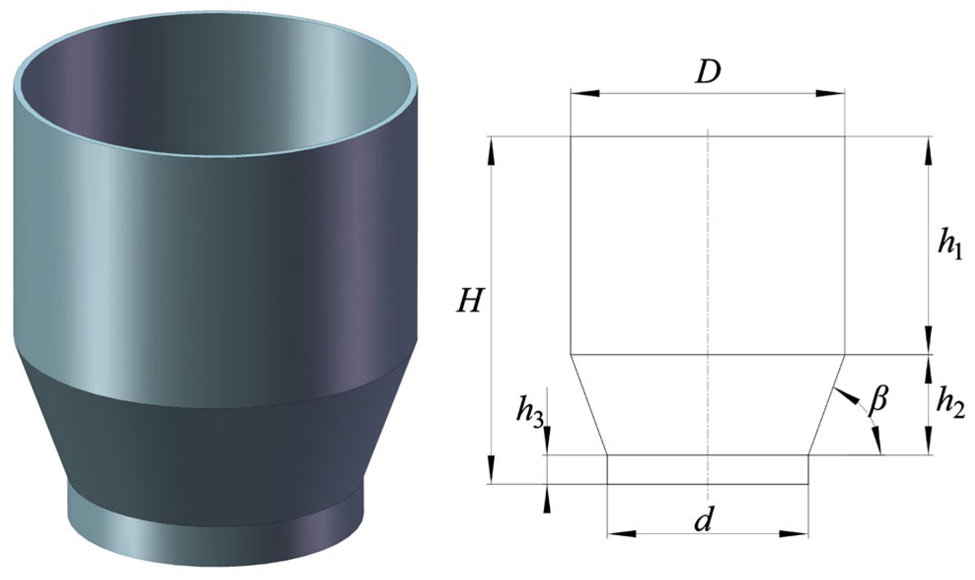
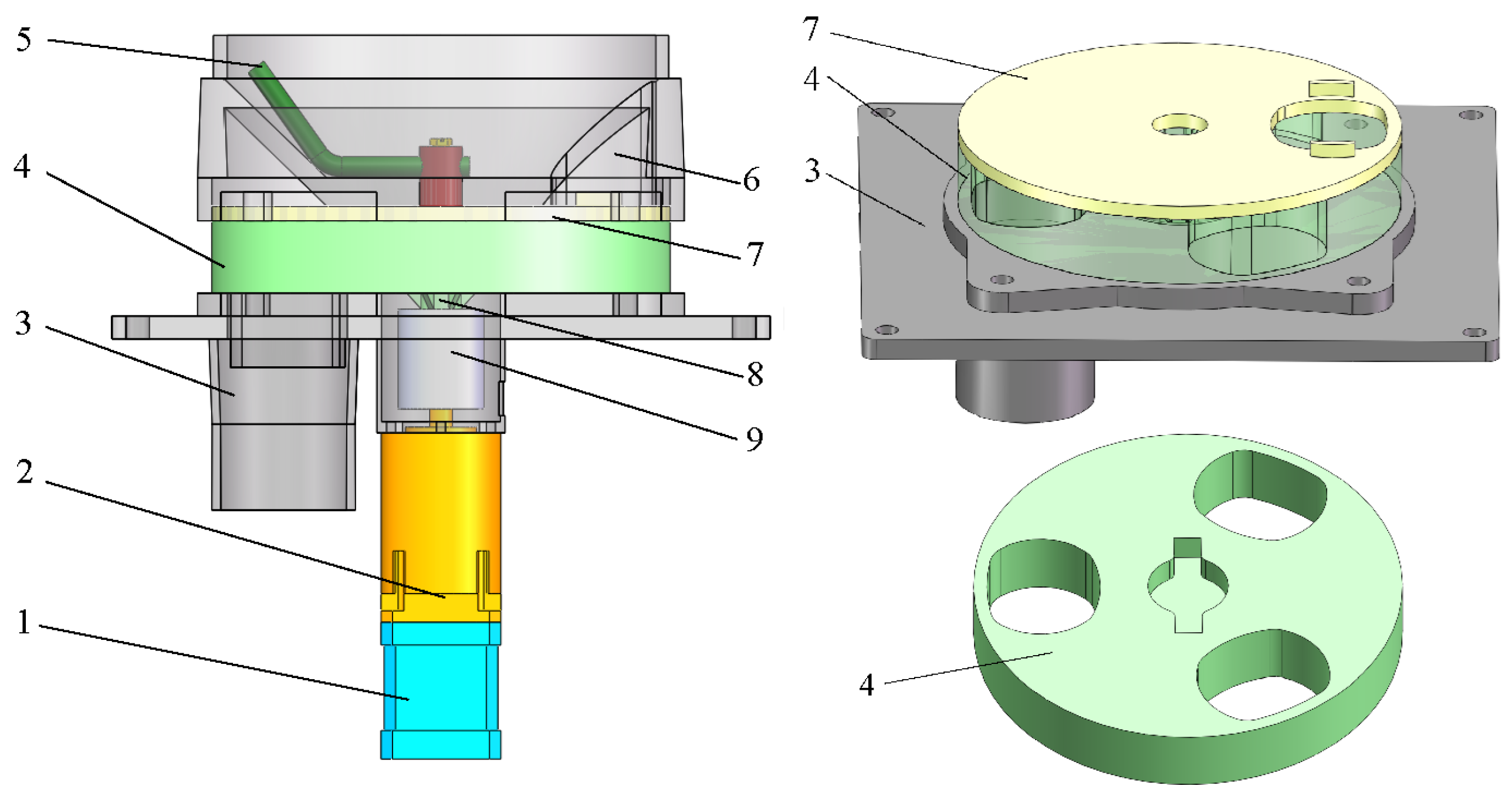
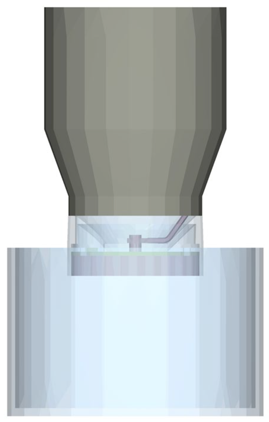
2.2. Hopper and Distribution Device Design

The particle flow patterns in the hopper are typically categorized as the entire and central flow. The stagnant areas are hardly observed in an entire flow hopper, and the feed pellets can flow uniformly towards the discharge outlet. In contrast, a stagnant area tends to be formed outside the flowing area in a central flow hopper. For the small-scale pneumatic conveying feeder, an entire flow hopper is generally chosen to prevent feed residue and spoilage. The main structure of the hopper is usually cylindrical or rectangular. A rectangular hopper generally requires more materials, with a relatively higher cost, and is prone to forming stagnant areas at the corners. Therefore, the cylindrical hopper is preferred. The common shape for the bottom of a cylindrical hopper is conical or flat. Small and medium-sized hoppers typically have conical bottoms, while large hoppers can have flat bottoms. A cylindrical body combined with a conical bottom was adopted to construct the hopper, as shown in Figure 1.
The hopper material can be made of ABS plastic to reduce friction between the feed pellet and the hopper wall, preventing feed pellet breakage and ensuring smooth flow at the bottom. To achieve this, the conical angle β at the bottom was designed to be 70°. Additionally, the capacity of the hopper requested by the actual production enterprise (Zhejiang Yulaoda Agricultural Technology Co., Ltd., Quzhou, China) was 4 kg, based on a maximum biomass of 100 kg in a single culture tank for farming broodstock. Based on the density of feed pellets (656.4 kg/m3), the effective volume of the hopper is 6.09 L. Considering a volume utilization rate of 0.85, the calculated volume of the hopper should be 7.16 L, which is defined as V. As shown in Figure 1, the volume of the cylindrical body (V1) and the volume of the conical bottom (V2) can be calculated as follows:
V = V 1 + V 2
It should also meet the following requirements:
V 1 = 1 4 π D 2 h 1 V 2 = 1 12 π h 2 ( d 2 + D 2 + D d ) h 2 = 1 2 ( D d ) tan β h 1 = H h 2 h 3
where D is the diameter of the cylindrical body (mm); d is the diameter of the discharge outlet (mm); h1 is the height of the cylindrical body (mm); h2 is the height of the conical bottom (mm); h3 is the height at the junction between the hopper and the feed distribution device (mm); H is the total height of the hopper (mm). Based on the overall dimensions, D was selected as 220 mm, d as 80 mm, and h3 as 25 mm. The corresponding calculations yield h2 as 83.52 mm, h1 as 151.48 mm, V1 as 5.76 L, V2 as 1.58 L, and the total calculated volume (V) as 7.34 L, meeting the requirements of the target hopper.
The diagram of the structure of the feed distribution device is shown in Figure 2. Due to the space limitation in the bottom of the small-scale feeder, a 42-type stepper motor with a shaft length of 22 mm, a body length of 48 mm, a step angle of 1.8°, a holding torque of 0.55 Nm, and a rated current of 1.5A was selected, combining a planetary reducer with a transmission ratio of 25, a rated torque of 14 Nm, an axial force of 100 N, and a transmission efficiency of 94%, which drives the discharge disk and stirring rod via a shaft coupling. The hopper connector is used to install the hopper securely. When the through-hole on the discharge disk aligns with the channel on the isolating board, feed pellets pass through the hopper connector and isolating board under the action of the stirring rod, and then are stored in the through-hole of the discharge disk. As the discharge disk rotates, when the through-hole storing feed pellets aligns with the channel on the base, the feed pellets are separated. The discharge disk completes a single separation of feed pellets in every rotation angle of 120°. The size of the through-hole on the discharge disk, along with its rotational speed, affects the single feeding quantity, which further determines the feeding accuracy. According to the overall structural layout, the diameter of the discharge disk is 160 mm, with the drive shaft installed in the center. Considering the parameters of the discharge disk and ensuring structural strength, the through-hole on the discharge disk is constructed by four segment arc structures, with an internal cross-sectional area of 1775 mm2. The thickness of the discharge disk is 25 mm.

2.3. Simulation Modeling Process

The precision of DEM simulation depends mainly on the selection of the feed pellet model, geometric model, contact model, and the settings of simulation parameters. Two methods are available for creating the feed pellet model: utilizing a spherical body directly within EDEM for simple, regular structures, or designing an irregular particle model in 3D modeling software, importing it as an STL format into EDEM, and then filling its internal space with a single spherical body. The expanded floating feed pellet used in this study has an average equivalent diameter of 6.75 mm and a sphericity of greater than 90%, enabling the direct adoption of a spherical body for DEM simulation [23]. To enhance computational efficiency and reduce memory usage, a spherical feed pellet model with a diameter of 6.75 mm was created in Altair EDEM 2022.2 (version 8.2.0), as shown in Figure 3.
To simplify the simulation process, the stepper motor, planetary reducer, and shaft coupling were removed. Instead, the rotational motion was applied to the discharge disk in EDEM to simulate the mechanical drive. The hopper was installed on the hopper connector to store the feed pellets generated by the particle factory. Meanwhile, a collection box was set below to observe the drop-off of separated feed pellets. The simplified geometric model was created using SolidWorks 2020 (version SP0.0, Dassault Systemes SolidWorks Corporation, Concord, MA, USA) and saved in IGS format before being imported into EDEM. The simulation model of the feed distribution device is shown in Figure 4.
The contact model is used to describe particle behavior. It can be regarded as a mathematical model that calculates the contact force and contact torque acting on two particles by inputting the relative translational and rotational motion:
F M T = f ( Δ x c , Δ θ c )
F and M denote the contact force vector and contact moment vector, respectively, while Δ x c and Δ θ c represent the relative translational displacement and the relative rotational angle, respectively.
In EDEM, the contact model is divided into the basic model, the friction model, and the additional model. Different contact models are suitable for different application scenarios, and their selection usually depends on the compressibility and viscosity characteristics of the particle. Since the feed pellet is approximately spherical with a smooth surface, and it has smooth contact with the ABS plastic, there is almost no adhesion among feed pellets and between feed pellets and ABS plastic. The basic Hertz–Mindlin (no slip) model was adopted for DEM simulations in this study, and was widely employed in similar studies of objects like coal and fertilizer particles [24,25]. The Hertz–Mindlin (no-slip) model is based on classical elastic contact theory, combining the Hertz normal contact model and the Mindlin tangential contact model [26]. The normal force during the collision of particles is calculated as follows:
F n = 4 3 E R δ n 3 2
where E is the equivalent Young’s modulus, R is the equivalent radius, and δ n is the normal overlap. In addition, the tangential force is defined as follows:
F t = 8 G R δ n δ t
where G is the equivalent shear modulus and δ t is the tangential overlap.
In the pre-processing interface of EDEM Creator Tree, the feed pellet model (Figure 3) and the ABS plastic were constructed respectively in the Bulk Material and Equipment Material interface, using the relevant parameters in Table 1. Then, the geometric model of IGS format (Figure 4) was imported into the Geometries interface. The rotational motion of the discharge disk was set with the relevant time, speed, and direction. A particle factory was established above the hopper, with settings for the total number and the generation rate of feed pellets. In the Physics and Environment interface, the appropriate contact model was selected, and the corresponding parameters and the gravity were set. Finally, in the Simulator Settings interface, the time step was set to 0.00001 s, the save interval was set to 0.01 s, the cell size was set to three times the smallest radius of 3.375 mm (3 R min), and the total simulation time was determined based on the total number of feed pellets and the discharge disk rotational speed.

2.4. Experimental Design

Before the experiments, an actual pre-test was conducted to determine the viable discharge disk rotational speed under the condition of the hopper filled with feed pellets, using a feed distribution device made by fused deposition modeling (FDM). The test proved that the maximum rotational speed of the discharge disk is 28 rpm. When the discharge disk rotational speed exceeds 28 rpm, namely the rotational speed of the stepper motor is greater than 700 rpm, the output torque of the stepper motor combined with the planetary reducer is smaller than the relevant resistances, including the force of feed pellets exerted on stirring rod and the friction between discharge disk and base.
Firstly, to assess the integrity of feed pellets, DEM simulations were used to analyze the motion and force changes during the distribution process under the condition of the discharge disk rotational speed set at 28 rpm. This is because high speed is relatively prone to causing potential feed pellet breakage. Secondly, discharge disk rotational speeds of 12, 16, 20, 24, and 28 rpm were adopted for DEM simulations and actual experiments, under the condition that the proportion of feed pellets in the hopper was controlled at 50%. In DEM simulations, the particle factory was set as dynamic, with a total of 15,000 feed pellets and 5000 feed pellets generated per second, starting from 0 s. At the end of the simulation, a single-body mesh was added during the post-processing to obtain the single feeding quantity. Five groups of single feeding quantities were recorded, and the relative error between simulation and actual experiment was calculated. Lastly, the proportions of feed pellets in the hopper were set to 15%, 35%, 55%, 75%, and 95%, with the discharge disk rotational speed set at 28 rpm. Five independent single feeding quantity data points were recorded, and the coefficient of variation was calculated. All data were processed in Microsoft Excel 2019 (version 16.0.10730.20102, Microsoft Corporation, Redmond, WA, USA) to evaluate the effects of discharge disk rotational speed and feed pellet proportions in the hopper on feeding accuracy. The optimal speed was also analyzed.

3. Results and Discussion

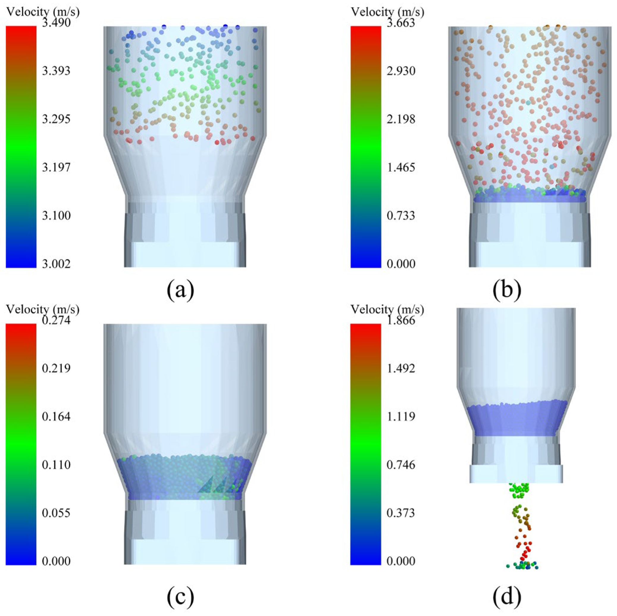
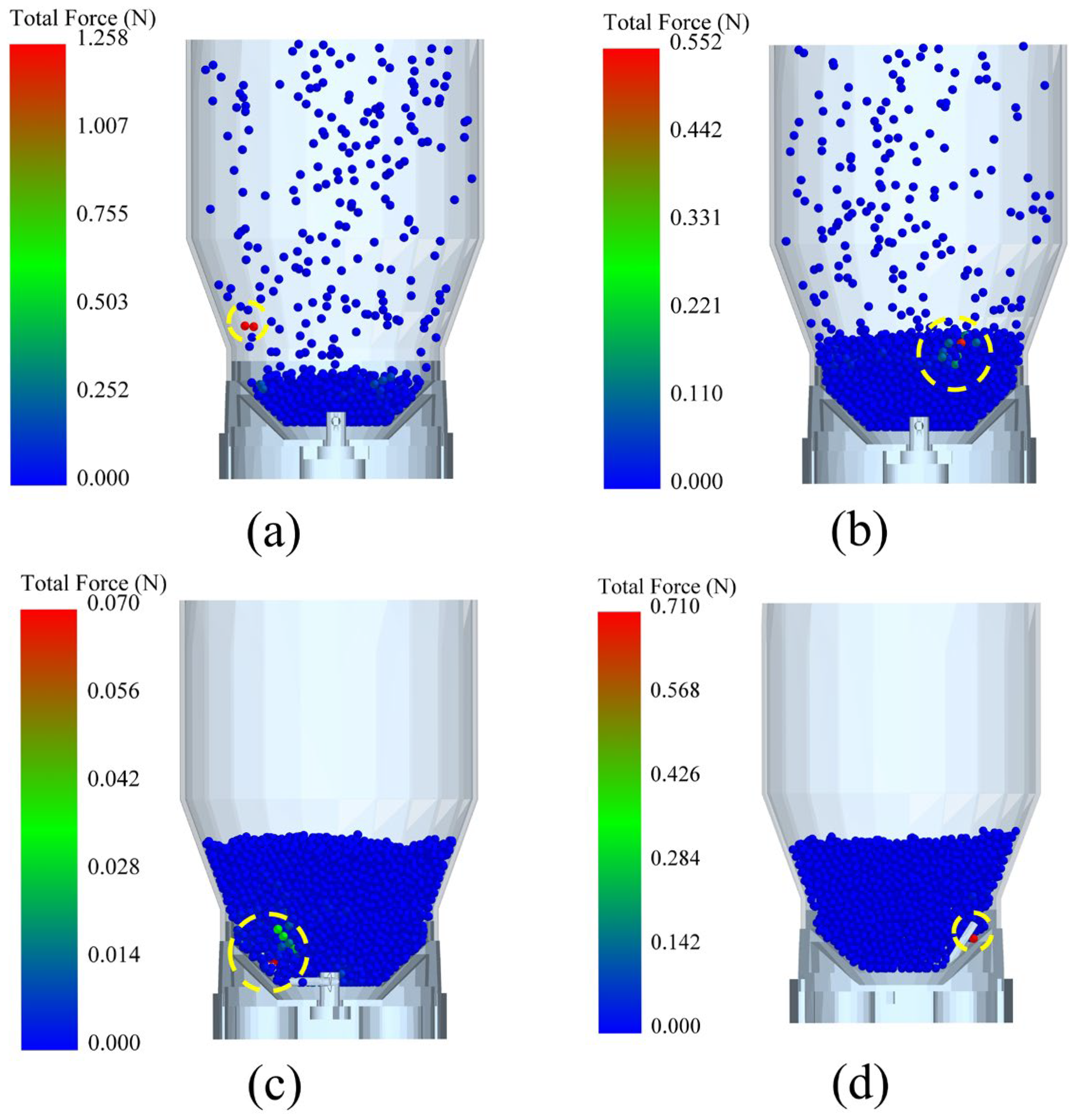
3.1. Motion and Force of Feed Pellets During the Distribution Process

Based on the DEM simulation, the motion of feed pellets in the feed distribution device can be divided into four typical stages. As shown in Figure 5a, the feed pellets were generated and released from the particle factory; they initially fell at a speed of 3 m/s to reduce generation time, and then entered the free-fall acceleration stage under the action of gravity. Figure 5b shows that when feed pellets reached the inner wall of the hopper or collided with each other, their velocity gradually decreased, and they eventually came to rest at the bottom of the hopper. Figure 5c shows that when the rotational components of the distribution device started to rotate, the stirring rod caused transient fluctuations in the partial speed of feed pellets. Figure 5d shows the distribution process where the through-hole of the discharge disk and the channel of the isolating board periodically encounter and separate, allowing the feed pellets to detach from the constraint and fall under gravity, eventually entering the collection box. Similarly, Aas et al. studied the effects of different air speeds (25, 30, 35 m/s) and feeding rates (9, 18, 36 kg/min) on feed pellet breakage in a pneumatic feeding system, indicating that the higher air speed and the lower feeding rate more easily led to feed pellet breakage, and the corresponding speed of feed pellets was above 17 m/s [27]. In addition, Kong et al. established the pneumatic conveying model using CFD-DEM simulation and analyzed the effects of inlet velocity and bend radius on feed pellet breakage, showing that the lower inlet velocity and larger bend radius could help reduce feed pellet breakage during the pneumatic conveying process, and the critical breakage velocity for a single feed pellet ranged from 16.1 to 19.8 m/s [15]. In contrast, the speeds of feed pellets obtained from this simulation are much lower than the speeds in the above two studies.
Figure 6 shows the changes in force on feed pellets during the distribution process. After the feed pellets were generated from the particle factory, they fell into the hopper. During this process, the maximum contact force between feed pellets was 1.258 N (Figure 6a), larger than the maximum contact force of 0.552 N when they reached the hopper bottom (Figure 6b). This phenomenon was mainly due to the initial velocity of 3 m/s when the feed pellets were generated. The shear strength of aquaculture feed pellets typically ranges from 1.03 to 1.14 MPa [28], indicating that the expanded floating feed pellets adopted in this study will not break under a force of 1.258 N. However, it is still recommended to slowly introduce the feed pellets into the feeder’s hopper to reduce the potential risk of mechanical damage during the actual operation. Figure 6c shows that the force exerted by the stirring rod with a circular cross-section on the feed pellets was small, and the maximum force only reached 0.070 N. This might be because the used feed pellet model was spherical, resulting in relatively low interaction forces between the feed pellets. Figure 6d shows that during the rotation of the discharge disk, the maximum force between the feed pellets was 0.710 N, which was also insufficient to cause feed pellet breakage. In general, DEM simulation results show that the motion speed and forces of feed pellets were within a reasonable range, ensuring the integrity of feed pellets and enabling a stable distribution function for the small-scale pneumatic conveying feeder.

3.2. Effects of Discharge Disk Rotational Speed on Single Feeding Quantity

Table 2 shows the single feeding quantities of the simulation and actual experiments at different discharge disk rotational speeds, with the proportion of the feed pellets in the hopper at 50%. As the rotational speed of the discharge disk decreased, the overlap time between the through-hole on the discharge disk and the channels on the hopper connector and isolating board gradually increased, leading to a gradual increase in the single feeding quantity. At a low discharge disk rotational speed of 12 rpm, the standard deviation of the single feeding quantity obtained from the simulation was too large. This was mainly due to the increase in the overlap time, which increased the random effects of interactions between the feed pellets during the distribution process. Therefore, an excessively low discharge disk rotational speed may cause instability in the distribution process, further affecting the feeding accuracy.
The single feeding quantities obtained from the actual experiments were all correspondingly lower than those from the simulation experiments. It was mainly due to the adoption of a spherical feed pellet model in DEM simulations, while the actual feed pellet is a cylindrical particle. Because of the irregular shape, the friction between the feed pellets and the hopper wall, as well as between the feed pellets themselves, was higher in the actual experiments, leading to a reduction in the flowability of the feed pellets. Moreover, the relative error between the simulation and the actual experiment increased as the discharge disk rotational speed decreased, reaching 24.98% at 12 rpm. This phenomenon was mainly attributed to the increased overlap time between the through-hole on the discharge disk and the channels on the hopper connector and isolating board, which intensified the random effects of interactions between the feed pellets. In related DEM simulation studies, the relative error is typically within 5%, indicating that the simulation can effectively reflect the actual situation [29,30]. Table 2 shows that the relative error between the simulation and the actual experiment was relatively low when the discharge disk’s rotational speed was set at the maximum of 28 rpm. In addition, the stepper motor combined with the planetary reducer can provide sufficient torque to drive the discharge disk, ensuring the feeding efficiency to some extent. Considering the mass of individual feed pellets, the single feeding mass obtained from the actual experiment was 62.74 g, which generally satisfies the distribution requirement of the small-scale pneumatic conveying feeder. Obviously, there is no doubt that the relatively less single feeding quantity is conducive to controlling the total feeding mass for a specific culture tank and avoiding potential feed waste, and that is also important for the intelligent feeder to adjust the feeding mass in real-time [31]. Therefore, the optimal discharge disk rotational speed should be set to 28 rpm in the designed feed distribution device.

3.3. Effects of Feed Pellet Proportion in the Hopper on Single Feeding Quantity

Five independent simulation experiments with five feed pellet proportions of 15%, 35%, 55%, 75%, and 95% in the hopper were performed at a discharge disk rotational speed of 28 rpm. The results are presented in Table 3. The average single feeding quantities ranged from 262 to 301 feed pellets. According to the above analysis, the relative error between the simulation and the actual experiment was low for the corresponding discharge disk rotational speed, while the coefficient of variation was 12.46% for the single feeding quantity under different feed pellet proportions. Taking the single feeding mass of 62.74 g into consideration, this variation has a negligible impact on the overall feed consumption demand of the target culture tank with a total biomass of 100 kg and a total feeding mass of 3~4 kg of feed pellets. In other words, the feeding accuracy affected by the proportion of feed pellets in the hopper is within an acceptable range; therefore, the feed distribution device developed in this study is suitable for a small-scale pneumatic conveying feeder.

4. Conclusions

A hopper with a capacity of 4 kg and a feed distribution device for a small-scale pneumatic conveying feeder were designed and evaluated. In the feed distribution device, the through-holes of the discharge disk and the channels of the hopper connector and isolating board intermittently encounter and separate to complete the distribution of feed pellets. The distribution process was simulated using the EDEM software, indicating no feed pellet breakage in view of motion and force. By comparing the simulation with actual experiments, it was suggested that a discharge disk rotational speed of 28 rpm was optimal. At this speed, the relative error between the simulation and actual experiments of single feeding quantity was 4.43%, and the effect of the proportion of the feed pellet in the hopper on single feeding quantity was negligible. In addition, the actual experiments showed a single feeding mass of 62.74 g in the trial-manufactured hopper and feed distribution device, which generally meets the feed distribution requirements of the small-scale pneumatic conveying feeder.

Author Contributions

Conceptualization, L.W. and M.J.; methodology, L.W.; software, L.W.; validation, M.J. and K.W.; formal analysis, L.W.; investigation, L.W.; resources, M.J. and X.W.; data curation, L.W.; writing—original draft preparation, M.J. and H.L.; writing—review and editing, M.J. and H.L.; visualization, K.W.; supervision, X.W.; project administration, X.W.; funding acquisition, M.J. All authors have read and agreed to the published version of the manuscript.

Funding

This research was funded by Quzhou Science and Technology Project (grant number 2024K072) and the Municipal Science and Technology Special Commissioner of Huzhou (grant number 2023KT09).

Institutional Review Board Statement

Not applicable.

Informed Consent Statement

Not applicable.

Data Availability Statement

Data are contained within the article.

Conflicts of Interest

Xudong Weng was employed by Zhejiang Yulaoda Agricultural Technology Co., Ltd. The remaining authors declare that the research was conducted in the absence of any commercial or financial relationships that could be construed as a potential conflict of interest.

References

  1. Wang, H.; Hou, H.; Liu, Y. Research progress and development trend in recirculating aquaculture system. Fish. Sci. 2023, 42, 735–741. [Google Scholar]
  2. Chen, W.; Gao, S. Current status of industrialized aquaculture in China: A review. Environ. Sci. Pollut. Res. 2023, 30, 32278–32287. [Google Scholar] [CrossRef] [PubMed]
  3. Zhou, C.; Xu, D.M.; Lin, K.; Sun, C.; Yang, X. Intelligent feeding control methods in aquaculture with an emphasis on fish: A review. Rev. Aquac. 2018, 10, 975–993. [Google Scholar] [CrossRef]
  4. Wang, Y.; Yu, X.; Liu, J.; An, D.; Wei, Y. Dynamic feeding method for aquaculture fish using multi-task neural network. Aquaculture 2022, 551, 737913. [Google Scholar] [CrossRef]
  5. Godoy-Olmos, S.; Jauralde, I.; Monge-Ortiz, R.; Milian-Sorribes, M.C.; Jover-Cerda, M.; Tomas-Vidal, A.; Martinez-Llorens, S. Influence of diet and feeding strategy on the performance of nitrifying trickling filter, oxygen consumption and ammonia excretion of gilthead sea bream (Sparus aurata) raised in recirculating aquaculture systems. Aquac. Int. 2022, 30, 581–606. [Google Scholar] [CrossRef]
  6. Liang, Q.; Liu, G.; Luan, Y.; Niu, J.; Li, Y.; Chen, H.; Liu, Y.; Zhu, S. Impact of feeding frequency on growth performance and antioxidant capacity of Litopenaeus vannamei in recirculating aquaculture systems. Animals 2025, 15, 192. [Google Scholar] [CrossRef]
  7. Chen, Z. Design and Experiment of an Intelligent Baiting Machine for Micropterus salmoides. Master’s Thesis, Huazhong Agricultural University, Wuhan, China, 2024. [Google Scholar]
  8. Wang, G. Design and Test of Automatic Feeding Equipment for Circulating Aquaculture. Master’s Thesis, Shandong Agriculture University, Tai’an, China, 2022. [Google Scholar]
  9. Zhu, M.; Zhang, Z.; Huang, H.; Chen, H.; Cuan, X.; Dong, T. Research progress on intelligent feeding methods in fish farming. Trans. CSAE 2022, 38, 38–47. [Google Scholar]
  10. Huang, H.; Zhang, Y.; Wang, D.; Fu, Z.; Tian, H.; Shang, J.; Helal, M.; Lv, Z. Study the flow capacity of cylindrical pellets in hopper with unloading paddle using DEM. Agriculture 2024, 14, 523. [Google Scholar] [CrossRef]
  11. Sun, W.; Sun, Y.; Wang, Y.; He, H. Calibration and experimental verification of discrete element parameters for modelling feed pelleting. Biosyst. Eng. 2024, 237, 182–195. [Google Scholar] [CrossRef]
  12. Huang, J.; Wen, J.; Li, H.; Xia, Y.; Tan, S.; Xiao, H.; Duan, W.; Hu, J. Particle erosion in 90-Degree elbow pipe of pneumatic conveying System: Simulation and validation. Comput. Electron. Agric. 2024, 216, 108534. [Google Scholar] [CrossRef]
  13. Zhao, S.; Ding, W.; Zhao, S.; Gu, J.; Zhang, J. Performance analysis and optimization of pneumatic fishpond feeder based on EDEM-Fluent coupling. Trans. CSAM 2019, 50, 130–139. [Google Scholar]
  14. Song, J.; Wang, T.; Hu, G.; Zhang, Z.; Zhao, W.; Wang, Z.; Zhang, Y. Conveying characteristics of shrimp feed pellets in pneumatic conveying system and minimum power consumption dissipation factor. Aquacult. Eng. 2023, 102, 102347. [Google Scholar] [CrossRef]
  15. Kong, X.; Liu, J.; Yang, T.; Su, Y.; Geng, J.; Niu, Z. Numerical simulation of feed pellet breakage in pneumatic conveying. Biosyst. Eng. 2022, 218, 31–42. [Google Scholar] [CrossRef]
  16. Liu, S.; Li, G.; Liu, H.; Zheng, H.; Chen, J. Current development status of aquaculture equipment in China. J. Fish. China 2023, 47, 119615. [Google Scholar]
  17. Le Boucher, R.; Chung, W.; Lin, J.; Tan, L.; Poon, Z.; Lee, C. Optimizing automated feeder algorithms for feed intake prediction in barramundi (Lates calcarifer). Aquaculture 2023, 577, 739909. [Google Scholar] [CrossRef]
  18. Son, S.; Jeong, Y. An automated fish-feeding system based on CNN and GRU neural networks. Sustainability 2024, 16, 3675. [Google Scholar] [CrossRef]
  19. Chang, C.; Fang, M.; Jao, R.; Shyu, C.; Liao, I. Development of an intelligent feeding controller for indoor intensive culturing of eel. Aquacult. Eng. 2005, 32, 343–353. [Google Scholar] [CrossRef]
  20. Halstensen, M.; Ihunegbo, F.N.; Ratnayake, C.; Sveinsvold, K. Online acoustic chemometric monitoring of fish feed pellet velocity in a pneumatic conveying system. Power Technol. 2014, 263, 104–111. [Google Scholar] [CrossRef]
  21. Liao, Y.; You, Y.; Wang, D.; Zhang, X.; Zhang, H.; Ma, W. Parameter calibration and experiment of discrete element model for mixed seeds of oat and arrow pea. Trans. CSAM 2022, 53, 14–22. [Google Scholar]
  22. Peng, F.; Zhang, L.; Li, Z.; Chen, J. Calibration and verification of DEM parameters of wet-sticky feed raw materials. Sci. Rep. 2023, 13, 9246. [Google Scholar] [CrossRef]
  23. Wang, L.; Ji, M.; Zheng, Y.; Zheng, Y. Measurement and calibration of discrete element parameters for extruded floating feed pellets and ABS plastic. J. Phys. Conf. Ser. 2025, 2951, 012070. [Google Scholar] [CrossRef]
  24. Zhang, J.; Wang, Q.; Niu, F.; Yu, X.; Chang, Z.; Wu, F.; Zhang, M. Simulation and verification of discrete element parameter calibration of pulverized coal particles. Int. J. Coal Prep. Util. 2024, 1–20. [Google Scholar] [CrossRef]
  25. Yuan, F.; Yu, H.; Wang, L.; Shi, Y.; Wang, X.; Liu, H. Parameter calibration and systematic test of a discrete element model (DEM) for compound fertilizer particles in a mechanized variable-rate application. Agronomy 2023, 13, 706. [Google Scholar] [CrossRef]
  26. Liu, W.; Jin, H.; Li, H.; Li, X.; Zheng, K.; Wei, Z. Calibration of simulation parameters for potato minituber based on EDEM. Trans. CSAM 2018, 49, 125–135. [Google Scholar]
  27. Aas, T.S.; Oehme, M.; Sørensen, M.; He, G.; Lygren, I.; Åsgård, T. Analysis of pellet degradation of extruded high energy fish feeds with different physical qualities in a pneumatic feeding system. Aquacult. Eng. 2011, 44, 25–34. [Google Scholar] [CrossRef]
  28. Zhang, N.; Liu, J.; Niu, Z.; Shi, L.; Liu, C. Experimental study on mechanical properties of pellet feed. J. Agric. Sci. Technol. 2019, 21, 82–90. [Google Scholar]
  29. Zhang, P.; Li, F.; Wang, F. Optimization and test of ginger-shaking and harvesting device based on EDEM software. Comput. Electron. Agric. 2023, 213, 108257. [Google Scholar] [CrossRef]
  30. Zhou, P.; Li, Y.; Liang, R.; Zhang, B.; Kan, Z. Calibration of contact parameters for particulate materials in residual film mixture after sieving based on EDEM. Agriculture 2023, 13, 959. [Google Scholar] [CrossRef]
  31. Zhang, L.; Li, B.; Sun, X.; Hong, Q.; Duan, Q. Intelligent fish feeding based on machine vision: A review. Biosyst. Eng. 2023, 23, 133–164. [Google Scholar] [CrossRef]
Figure 1. The structure of the cylindrical hopper.
Fishes 10 00255 g001
Figure 2. Diagram of the structure of the feed distribution device. (1) Stepper motor; (2) planetary reducer; (3) base; (4) discharge disk; (5) stirring rod; (6) hopper connector; (7) isolating board; (8) drive shaft; (9) shaft coupling.
Fishes 10 00255 g002
Figure 3. The spherical feed pellet model.
Fishes 10 00255 g003
Figure 4. Simulation model of the feed distribution device.
Fishes 10 00255 g004
Figure 5. Changes in the speed of feed pellets. (a) Pellets fall from the particle factory; (b) pellets reach the hopper bottom; (c) the distribution device starts to work; (d) pellets fall into the collection box.
Fishes 10 00255 g005
Figure 6. Changes in the force of feed pellets. (a) Pellets fall from the particle factory; (b) pellets reach the hopper bottom; (c) the distribution device starts to work; (d) pellets fall into the collection box.
Fishes 10 00255 g006
Table 1. DEM simulation parameters for expanded floating feed pellets of Tongwei-180-5.0.
CategoryParametersValue
Feed pelletsPoisson’s ratio0.3
Shear modulus/MPa33.08
Density (kg/m3)656.4
Equivalent diameter (mm)6.75
ABS plasticPoisson’s ratio0.34
Shear modulus/MPa3000
Density (kg/m3)1250
Contact parameters between the feed pellet and ABS plasticRestitution coefficient0.533
Static friction coefficient0.331
Rolling friction coefficient0.069
Contact parameters among feed pelletsRestitution coefficient0.550
Static friction coefficient0.520
Rolling friction coefficient0.149
Table 2. Single feeding quantities of the simulation and actual experiments at different discharge disk rotational speeds.
Discharge Disk Rotational Speed (rpm)
2824201612
Simulation259 ± 25323 ± 26425 ± 26503 ± 65709 ± 101
Actual248 ± 24292 ± 33354 ± 28418 ± 33570 ± 72
Error4.43%10.62%13.33%20.33%24.98%
Table 3. Single feeding quantities at different proportions of feed pellets in the hopper.
Feed Pellet Proportion (%)1535557595Coefficient of Variation
Single feeding quantity262 ± 17297 ± 36301 ± 43296 ± 43286 ± 3512.46%
Disclaimer/Publisher’s Note: The statements, opinions and data contained in all publications are solely those of the individual author(s) and contributor(s) and not of MDPI and/or the editor(s). MDPI and/or the editor(s) disclaim responsibility for any injury to people or property resulting from any ideas, methods, instructions or products referred to in the content.

