1. Introduction
Rapid advancement in digital techniques had transformed the style of storage and transmission of multimedia data. With the availability of the communication network and the World Wide Web (WWW), digital data can travel from one source to an endless range of destination in any part of the globe. Notwithstanding these advantages, the digital domain representation of data also has a downside. The artworks in the form of a digital image can be used illegally, tampered with, and copied with an eye to copyright violation. This property of digital technology has encouraged thieves and discouraged the creator and the owner of digital artworks. Digital data hiding (watermarking) becomes a potential solution to address the above problems. Data hiding is a method of inserting an auxiliary message within the original data satisfying a few essential requirements [
1,
2]. However, it is very difficult to meet all these requirements simultaneously with the highest degree of accuracy. The design of data hiding techniques governed by widely diverse factors such as character and availability of the cover data, visibility/non-visibility of metadata, choice of embedding space and location, degree of resiliency against unintentional or intentional attacks on the data, etc. The watermark can be embedded in the spatial domain or frequency domain depending on the desired application. It is seen that the frequency domain methods are more robust than the spatial domain techniques [
3].
The large numbers of data hiding techniques modify the cover media in order to embed the watermark information. The modification is very small and imperceptible to human visual systems (HVS). However, the original cover media cannot be restored entirely. In other words, those schemes are irreversible data hiding techniques. But the irreversibility is not permissible to some applications, such as legal, forensic image archiving, and medical imaging [
4]. Medical images are normally collected in hospitals or research centers due to the nature of the specialized equipment [
5]. There are standard means like DICOM (Digital Imaging and Communications in Medicine) that enable the management, storage, and impression of medical images in standard formats [
6]. For medical imaging applications, reversible data hiding is used to extract the embedded information as well as to restore the original host signal. In other words, reversible watermarking schemes are also often known to as lossless, invertible, or distortion-free, data hiding technique, and it is a very prominent research area in the last few years [
4].
The idea of a reversible watermarking technique initially proposed and patented by Eastman Kodak [
7]. Xuan et al. [
4] embed watermark information into the high-frequency wavelet coefficients by companding technique. The Laplacian-like distribution of integer wavelet coefficients helps to select the compression and expansion functions. Tang et al. [
8] develop a novel encryption scheme to serve the purpose of data hiding in the reversible domain. Their scheme improves the embedding capacity with a minimum computational burden. Tian [
9] described a reversible watermarking scheme based on difference expansion (DE). This scheme uses location map to embed watermark. The term ‘location map’ is the selected positions of the pixels or the coefficients. The method selects the pixels or the coefficients from the location map to modulate during the process of watermark embedding. The major drawback of this scheme is the lack of capacity control due to insertion of the compressed location map in conjunction with the true payload. Hence the system will suffer from low embedding rate and also the lack of visual quality of the watermarked image. Jinna and Ganesan [
10] proposed a reversible data hiding scheme using bit-plane coding and wavelet transform based on lifting. The performance of the scheme for several types of noise and attacks is tested. However, it is seen that when the noise level is high and also affecting the major part of the image, the watermark is extracted wrongly.
Xiaolong et al. [
11] proposed the prediction-error expansion (PEE) technique for reversible watermarking, which embeds data uniformly. The scheme adaptively embeds one (1) or two (2) bits into the expandable pixel, based on local complexity. Lee et al. [
12] proposed a data hiding scheme that divides the host image into non-overlapping blocks. The scheme then embeds a watermark into the high-frequency wavelet coefficients of the above blocks. Authors argue that the scheme offers superior embedding capacity, and also the embedding distortion is maintained at a lesser level. Sachnev et al. [
13] present a reversible data hiding scheme for images without using the location map. The scheme uses prediction errors to embed data into the host image. A sorting technique is used to trace the prediction errors depending on the amount of its local variance. A reversible data embedding technique is proposed based on integer wavelet transform by Weng et al. [
14]. Data insertion is done by increasing the differences between one pixel and each of its three adjacent pixels. Liu et al. [
15] combine data hiding and image encryption to provide integrity/security in the cloud computing environment. The scheme uses block compressive sensing (BCS) technique to compress and encrypt the image. Then hidden data bits are embedded into the least significant nibble. The main feats of the scheme are improved compression, data-loss prevention, and embedding capacity.
Most of the current solutions found in the literature compromise between the quality of the reproduced medical image and the numbers of effective watermark bits inserted, which are indicators of the strength of the authentication and originality mechanisms of solution. Moreover, due to the reduced number of effective inserted bits, the strength of the current solutions is highly vulnerable, and it can be broken with simple security algorithms or brute force attacks [
16,
17]. Lastly, the schemes proposed in ([
4,
9]) embed location map as side information for restoration of the host image. That ultimately reduces the effective embedding capacity of a scheme.
Li et al. [
18] proposed a prediction error expansion (PEE) based reversible watermarking technique where multiple histogram modification mechanism is used for better embedding performance. The method performs better than conventional PEE methods in terms of watermarked image quality, but it has limited embedding capacity. An improved implementation of pixel value ordering (IPVO) system is reported by Ou et al [
19]. The method has better embedding performance than other IPVO based reversible watermarking technique but the time and space complexity of the system are high. Recently, another improved pixel value ordering (IPVO) technique is proposed by Weng et al [
20]. The system uses dynamic IPVO technique which offers better embedding performance with good visual quality.
To resolve the problems stated above, we proposed a novel reversible data hiding (watermarking) scheme that combining lifting based DWT with companding. The multi-resolution signal decomposition by wavelets transform reflects the anisotropic properties of the human visual system more exactly and helps to design data hiding scheme with high fidelity of the watermarked image [
21,
22]. Because of the small changes in wavelet coefficients distort the image very less. Moreover, unlike previously proposed reversible watermarking techniques [
9], this novel approach does not use any location map. So the scheme does not require to embed the location map in the host image that ultimately helps to achieve high fidelity and greater payload capacity of the watermarked image. The proposed data hiding encoder select all the coefficients of high-High (
HH) frequency sub-band to embed the watermark bits, whereas the decoder selects the same frequency sub-band to retrieve the embedded watermark bits. In other words, the data embedding technique modulates all the high-High (
HH) sub-band co-efficient. So the proposed scheme does not require any location information but use the particular sub-band i.e.,
HH sub-band to decode the watermark bits. Hence the scheme does not require transmitting location map with the host data. This proposed location map free technique gives better payload capacity with good visual quality. The significant contributions are performance study in various lifting based DWT, Rayleigh fading wireless channel, and collusion attacks. The scheme can also unambiguously distinguish parties involved in collusion operation and innocent users. The simulation results demonstrated the performance efficiency of the proposed scheme. Side by side, the results are compared with related data hiding methods.
The rest of the paper is structured as follows:
Section 2 describes the key features of the DICOM file format.
Section 3 focuses on lifting based DWT transform.
Section 4 discusses the basic of companding technique.
Section 5 explores the algorithm for embedding and extracting the watermark.
Section 6 presents the experimental results to show the effectiveness of the proposed data hiding method, and
Section 7 describes conclusions and the scope of future work.
2. Key Features of DICOM File Format
Digital Imaging and Communications in Medicine (DICOM) is the international standard for formatting, exchanging, and storing medical images and related data for clinical use. It also includes a network communications protocol that uses TCP/IP to communicate between systems [
23]. DICOM files can be interchanged between two persons that are capable of receiving images and patient information in DICOM file format. Digital medical images could be generated form diagnostic modalities such as Ultrasound, Nuclear Medicine, digital radiography, X-ray and hospital information system, etc. [
24]. Nowadays, DICOM is used in radiology, cardiology imaging, radiotherapy device, ophthalmology, and dentistry. In other words, DICOM is widely used in most of the healthcare messaging standards in the world [
24]. The digital watermarking techniques should employ necessary steps so that the quality of medical images are not degraded and are still conform with Digital Imaging and Communication in Medicine (DICOM) format. Any degradation of the medical image’s quality could lead to misdiagnosis, and that is somewhat unacceptable. However, in the case of natural images, there is no such hard restriction about the quality of the watermarked natural image.
Each DICOM file has a header which contains the patient’s name, type of scan, patient demographic information, acquisition parameters, practitioner & operator identifiers, and image dimensions, etc. The remaining portion of the DICOM file contains the image data. Because they often contain multiple high-resolution images, DICOM files tend to be large and are frequently compressed before storage and transfer [
25]. An illustration of the basic file structure is shown in
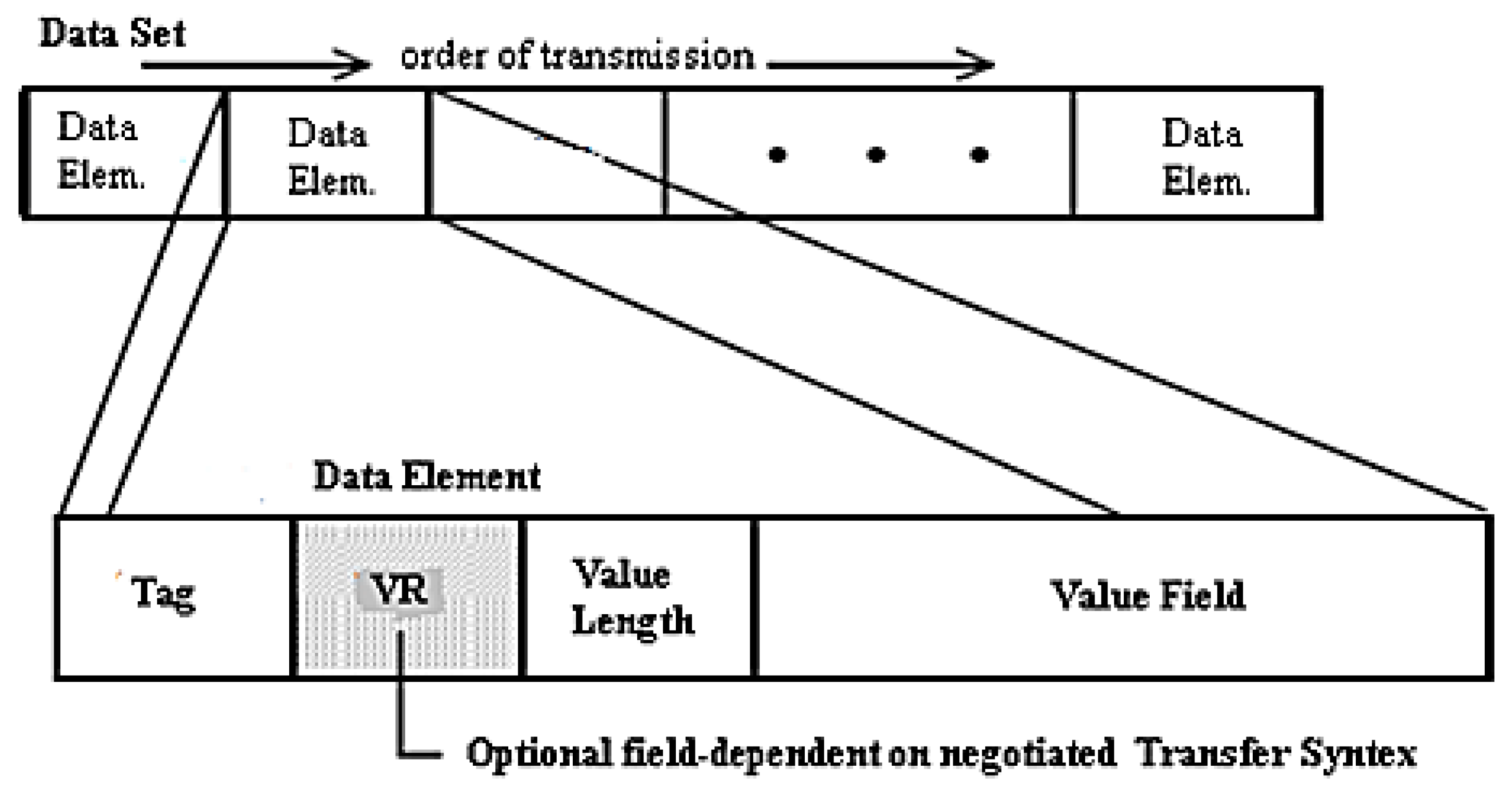
Figure 1. The header consists of a 128 byte File Preamble, followed by a 4-byte DICOM prefix. A Data Set represents an instance of a real-world Information Object. A Data Set is constructed of Data Element. Data Elements contain the encoded values of attributes of that object.
Figure 2 shows the DICOM data set and data element structures. The Data Element structure consists of the following fields: Tag, Value Representation, Value Length, and the Value [
26].
- (a)
Tag: The identifier of the data element; it consists of 32 bits unsigned integer, 16 bits for the Group Number, and 16 bits of the Element Number.
- (b)
Value Representation: It specifies the data type of the value field (byte, integer, character).
- (c)
Value Length: It specifies the length of the value field (number of bytes).
- (d)
Value: It represents the data value of this data element.
4. Overview of Companding
Companding is a technique that is commonly used to implement nonuniform quantization in speech communications to achieve high signal-noise-ratio (SNR). The technique is based on compression (
C) and expansion (
E) function [
32]. Commonly, the technique first compresses a signal and then expands it [
4]. Here, compression does not mean to say data compression. Instead, compression here represents the change in a dynamic range of the original signal to a narrower range and after the expansion of the compressed signal; the expanded signal would be close to the original signal. Now, for a signal
x,
C and
E correlate as follows:
If Equation (3) is satisfied, this technique can be effectively used in reversible data hiding [
4]. However, in the case of the digital signal,
CQ and
EQ, respectively represent the quantized versions of
C and
E, where
Q denotes quantization function [
14]. The quantization function (
CQ) is represented as:
where sign(∙) is the sign function. The expansion function (
EQ) is represented as:
The value of companding error (
r) is calculated as [
14]:
Though there is a companding error (r) in the digital case, the present scheme neither does nor requires the information ‘r’, to loss lessly restore the image, unlike other techniques found in the literature. So in the present scheme, the effective capacity is equal to the size of the payload. It is also to be noted here that due to integer coefficients of lifting based DWT, companding technique would return low loss in watermarked image fidelity (due to floor function used in Equation (5)) than the traditional DWT that returns fractional value of coefficients after transformation.
Assume we have value x = 250, we would like to embed one bit W = 1. First, the value ‘x’ is divided by two based on Equation (5.) i.e., . Next, we represent the quantized value into its binary representation i.e., . Then we append ‘W’ into the binary representation of after the least significant bit (LSB), the new modified value will be . Mathematically, this is equivalent to which is considered as a watermarked coefficient. From the embedded coefficients, we can extract the embedded bit and restore the original coefficients. The watermark bits are extracted by investigating the least significant bit (LSB) of the watermarked signal.
5. Proposed Algorithm
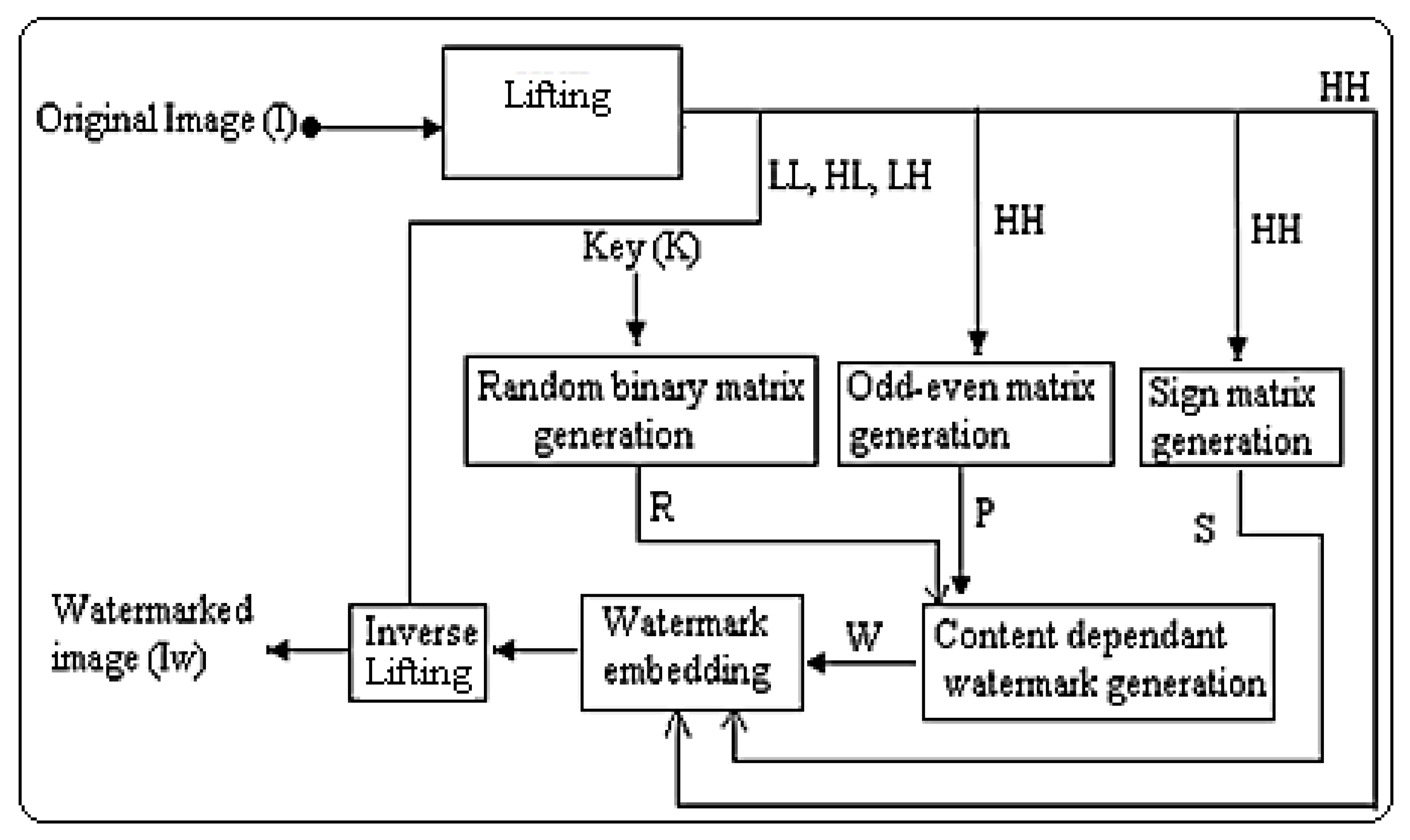
The proposed reversible watermarking scheme consists of two main modules, namely, data encoding and data decoding. The encoding module hides a watermark into the cover image. On the other hand, the decoding scheme extracts the embedded watermark and also recovered the original host signal. The block diagrams of the proposed encoding and decoding process are described in
Figure 4 and
Figure 5, respectively.
5.1. Data Encoding
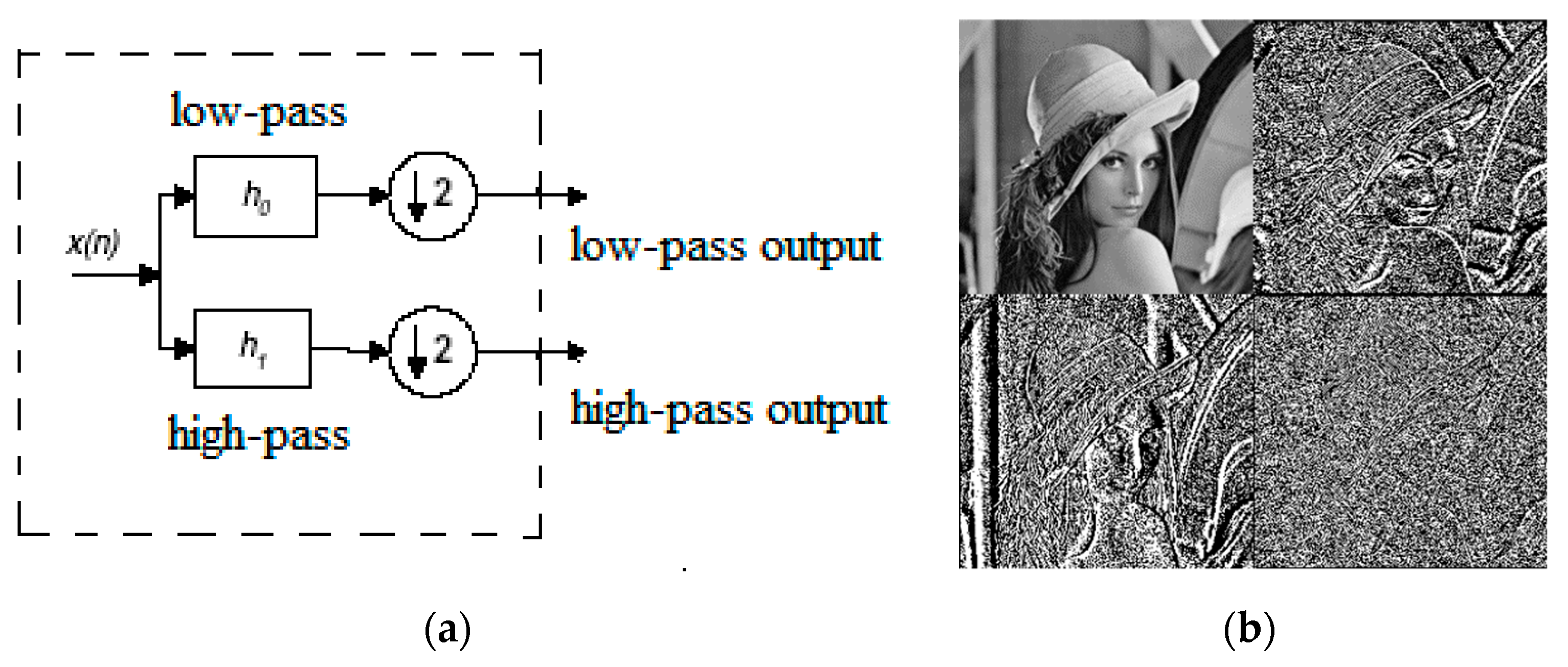
Step 1: Image transformation: Original host image (I) is decomposed into four sub-bands, i.e., low-low (LL), low-high (LH), high-low (HL), and high-high (HH) using lifting based DWT. One may use a higher level of decomposition for batter results.
Step 2: Selection of wavelets coefficients for watermark embedding: The scheme selects
HH sub-bands, as this component contains both the characteristics of horizontal and vertical edge components. Moreover, the choice of embedding the watermark information into the
HH sub-bands was motivated by experimental tests, as this one offers the best compromise between robustness and invisibility. Moreover, in the case of scalable decoding, if only the high-energy sub-bands are sent to the decoder, the watermark can be detected efficiently from those sub-bands without waiting for the others [
30]. It is also to be noted here that if other sub-bands are used, then capacity will also be increased.
Step 3: Generation of the odd-even matrix: The odd-even matrix (P) is generated from HH sub-band according to the following rule.
It is to be pointed out that the size of P and HH are the same.
Step 4: Generation of sign matrix: A sign matrix (S) is generated from HH sub-band according to the following rule.
It is also to be pointed out that the size of S and HH are the same.
Step 5: Generation of random binary matrix based on user-defined key: A binary pseudorandom matrix (R)is created depending on the secret key (K) supplied by the owner.
Step 6: Generation of watermark bit: The straightforward countermeasure against the collusion (average) attack is done by designing the watermark that depends on the host signal. A content dependent watermark (W) is produced depending on P&R, according to the following rule.
The symbol represents bit by bit XOR operation.
Step 7: Change of dynamic range: The coefficients of
HH bands are divided by two. This is analogous to compression operation as the above division operation changes the dynamic range of wavelet coefficient for the original host signal to a smaller range [
4]. This operation will prevent overflow/underflow after data embedding.
The symbol HHn represents the high-high sub-band after the change of dynamic range. The function abs (.) returns the absolute value of a signal.
Step 8: Watermark bit embedding: Then the watermark bits are embedded into the
HH sub-band according to the following rule:
The symbol HHw represents the watermarked coefficients. Then the sign matrix(S) is multiplied with HHw, to get the final watermarked HH sub-band.
Step 9: Inverse image transformation: Then, inverse lifting operation is done, and the watermarked image (Iw) is created.
5.2. Data Decoding
Step 1: Image transformation: Decompose the watermarked image (Iw) into 4-subbands, i.e., low-low (LL), high-low (HL), low-high (LH), and high-high (HH), using lifting.
Step 2: Watermark information (bit) extraction: The watermark bits (W′) are extracted by investigating the least significant bit (LSB) of HH sub-bands.
Step 3: Generation of random binary matrix based on user-defined key: A binary pseudorandom matrix (R) is created depending on the secret key (K) supplied by the owner that was used at watermark embedding time.
Step 4: Extraction of odd-even matrix pattern: Then odd-even matrix pattern (P′) is generated based on the extracted watermark W′.
Step 5: Generation of sign matrix: A sign matrix (S) is generated from HH sub-band, according to Equations (10) and (11).
Step 6: Restoration of HH sub-band of watermarked image: The watermarked HH sub-band is restored to its original form according to the following rule.
The symbol represents the restored HH sub-band. Then inverse lifting operation is done to reconstruct the original host image (I).
6. Performance Evaluation
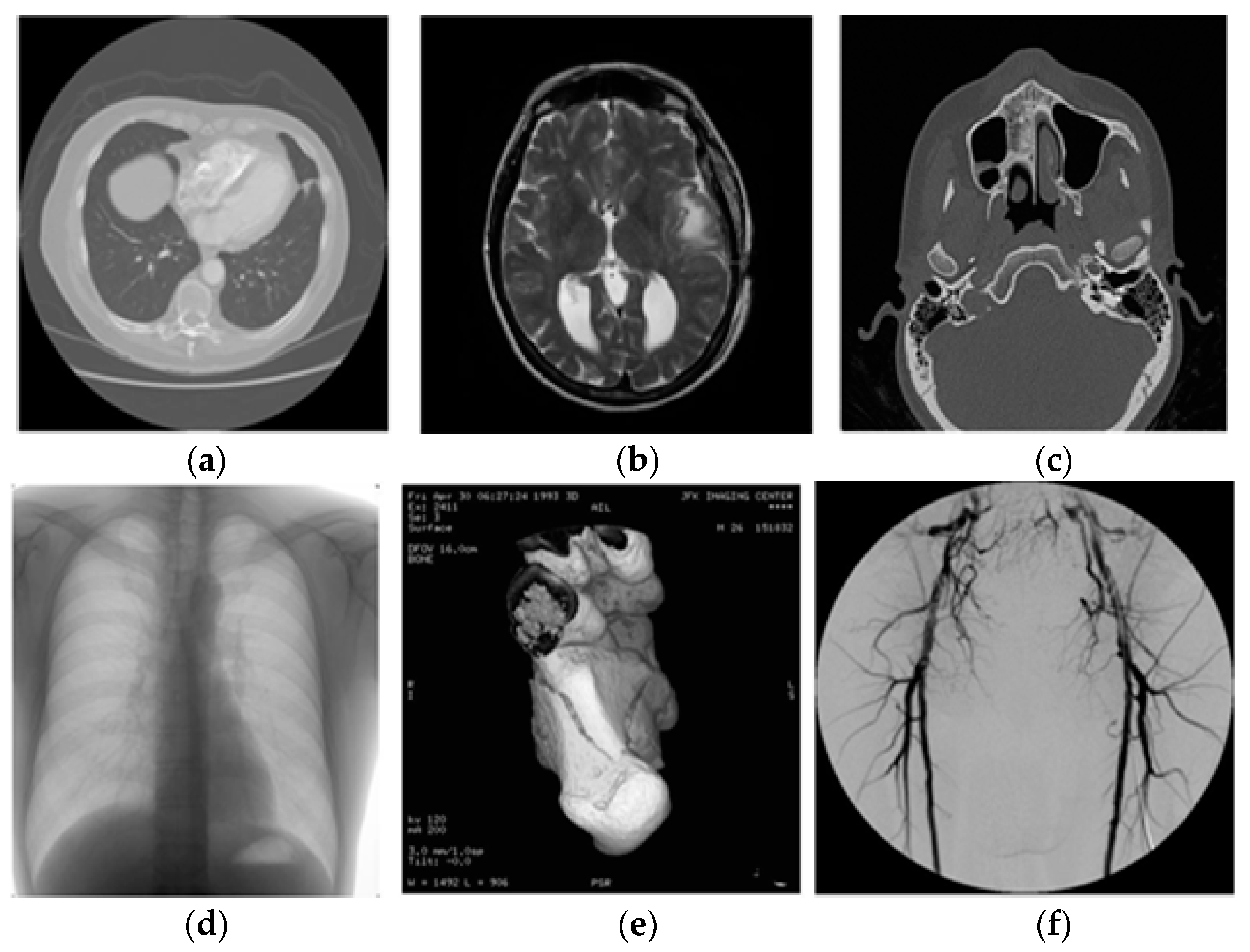
The performance of the proposed reversible watermarking scheme is evaluated over various DICOM medical images having diverse image features and characteristics. The test medical images are of size (512 × 512). All experimentations are evaluated in Pentium 4, with 512 MB RAM and 2.80 GHz processor, by MATLAB 7.
The present study uses Mean-Structure-Similarity-Index-Measure (MSSIM) [
33] and Peak–Signal-to-Noise-Ratio (PSNR) as distortion measures for the watermarked image. On the other hand, the relative entropy distance (Kullback Leibler distance (KLD)) [
3] is used to quantify the security (K) of the proposed scheme. The large Peak–Signal-to-Noise-Ratio (PSNR) and Mean-Structure-Similarity-Index-Measure (MSSIM) values and low-security values of the watermarked medical image represent better imperceptibility and security of the hidden data, respectively [
34]. PSNR is defined as:
The symbol MAX represents the maximum gray value of pixel for the DICOM medical image. Mean Square Error (MSE) is represented as:
where, the symbol ‘
X’ is the gray value of the pixel for the original DICOM host image and ‘
’ is the gray value of pixel for the watermarked DICOMimage. The symbol ‘
M’ and ‘
N’ are the height and width of the host image, respectively. MSSIM [
33] is defined as:
where,
where the symbol ‘
P’ and ‘
’ are the original and the distorted DICOM image signals, respectively. The symbol ‘
M′’ represents the number of local windows in the DICOM image. The symbol ‘
Pj′’ and ‘
’ are the image information at the j′-th local window. The functions
,
and
are the luminance, contrast, and structure comparison functions respectively. The symbols
α,
β, and
γ {where
α > 0,
β > 0,
γ > 0} are the parameters used to control the relative weight of the above components. The KLD (D(a||b)) is represented as [
3]:
where the symbol
and
representsthe probability distribution functions (PDF) of the random variables
R (i.e., original host image) and
S (i.e., watermarked image), respectively. The symbol
Ea represents the expectation concerning the joint distribution ‘a’. If
a(
X) =
b(
X) the security value is always non-negative or zero. On the other hand, the security value may be assumed to be ‘
K’ if
D (
a||
b) ≤
K [
3]. In the proposed scheme, the normalized cross-correlation (NCC) is used to quantify the quality of the extracted watermark [
34]. The NCC value between the original watermark image (
W) and the extracted watermark image (
W′) is represented as:
Figure 6 shows the test images.
Figure 7 shows the few decomposed images using lifting.
Figure 8 and
Figure 9 show the watermarked images along with PSNR, MSSIM, and ‘
K’ values and also the restored images, respectively. From
Figure 8 and
Figure 9, it is cleared that the watermark is embedded in the DICOM host image without decreasing the fidelity/quality of the image. Moreover, the image is restored completely by the proposed scheme.
Table 1 shows the variation of PSNR, MSSIM, and KLD values for the images shown in
Figure 6. As expected with the increase in payload size, the quality in term of PSNR (dB) of the watermarked image is decreased. It is also seen that due to the increase of payload size, there is no such deviation in structural values of watermarked images. It is quite interesting to see that for MRI-2 image, and there is no change in structural value even if the payload size is increased to 65,536 bits. It is also to be noted that with the increase in payload size, the value of KLD is also increased. However, till the KLD value is very low and approaching to zero (0). That ensures that the scheme is secured. The performance of different lifting based wavelets on the test images is shown in
Table 2. It is seen that ‘haar’, ‘db1′ and ‘bior1.1′ offers better performance than the other wavelets. On the other hand, the performance of various wavelets and their image security value for a fixed payload of 65,536 bits is shown in
Table 3. It is seen that in all test cases, the KLD values are very less and approaching to zero (0). That ensures that the scheme is secured for all type of lifting based wavelets.
Table 4 shows the variation of PSNR, MSSIM for different payload size (for Lung image), and wavelets. It is seen that ‘Haar’, ‘db1′ and ‘bior1.1′ offers better performance than the others wavelets even if the payload is increased to 65,536 bits.
To study the performance for collusion operation, we simulate fading like operation on watermarked DICOM image. We call this operation as a fading based collusion operation. Commonly, when collusion attack occurs on a continuous multimedia signal such as audio, video and DICOM images, the evaluation of time-varying weights (TVW) become vital which is equivalent to different gains in fading channels. Fading in communication channel means random deviation in received signal strength. This occurs as multiple copies of the same message signal are received over variable path lengths [
35,
36]. A robust Multi-Carrier-Code-Division-Multiple-Access (MC-CDMA) based fingerprinting scheme against time-varying collusion attack, which is analogous to fading, is proposed in [
37]. The algorithm uses multicarrier approach for codeword generation (i.e., Hadamard-Walsh codes), time-varying channel response for colluder weight evaluation, and the Maximal Ratio Combining (MRC) detector [
36]. It is quite reasonable to accept fading operation as collusion-like as colluders would develop an average watermarked DICOM frame through variable weights instead of equal weight to remove their identities.
To simulate collusion operations, five different watermarks (each watermark (
Wi) is a pseudo-random binary sequence generated based on secret Key (K)) are embedded in host DICOM images and five different watermarked images are obtained. In the present scheme, we have tested the anti-collusion performance of the proposed reversible watermarking algorithm by transmitting first (in fact it is a random choice from the total set) four (e.g.) watermarked DICOM frame using MC-CDMA [
35] through Rayleigh fading wireless channel. Transmission is done at different Signal-to-Noise-Ratio (SNR) values changing from 50 dB to 100 dB. In the present test, we keep SNR value to very high as DICOM images are very sensitive to noise than traditional images. The resultant received watermarked DICOM frames are then averaged. Transmission of watermarked DICOM frames through Rayleigh fading channel followed by the averaging operation is one way of implementing collusion operation. In the mobile radio communication system, the low value of SNR suggests that the channel is under deep fade. On the other hand, the high value of SNR represents the opposite. In the present scenario, high and low SNR values represent light and heavy collusion operations, respectively [
29]. We also test the anti-collusion performance of the proposed scheme by directly averaging watermarked DICOM frame, but without channel fading. This operation is called a non-fading based collusion operation.
Figure 10 shows a few frames from ‘Lung’ DICOM image database.
Figure 11a shows a watermarked frame after non-fading based collusion operation.
Figure 11b–f show watermarked DICOM frames after time-varying collusion attacks with different SNR (transmitting each watermarked DICOM frames through fading channel at different SNR values) and then averaged.
Table 5 shows the BER (bit error rate) values for different watermarks extracted from the colluded average images. Low BER values indicate that the scheme is robust to fading like collusion operation. It is also seen that the BER values for
columns 2–5 are quite low compared to the BER values in
column 6. The low values of BER clearly indicate that the parties having watermarks, i.e., W
1, W
2, W
3, W
4, are identified as colluders. It is also quite clear from the numerical values of BER that parties involved in collusion operation would unambiguously be identified from the innocent users (W
5). Similar results are also obtained if different combinations of watermarked images in the set are used in collusion operations.
Table 6 shows the average results for non-fading based collusion operation. High NCC values in
Table 6 indicate that the scheme is also robust to non-fading based collusion operation.
Table 7 shows the average value of the colluder identification performance of the proposed scheme.
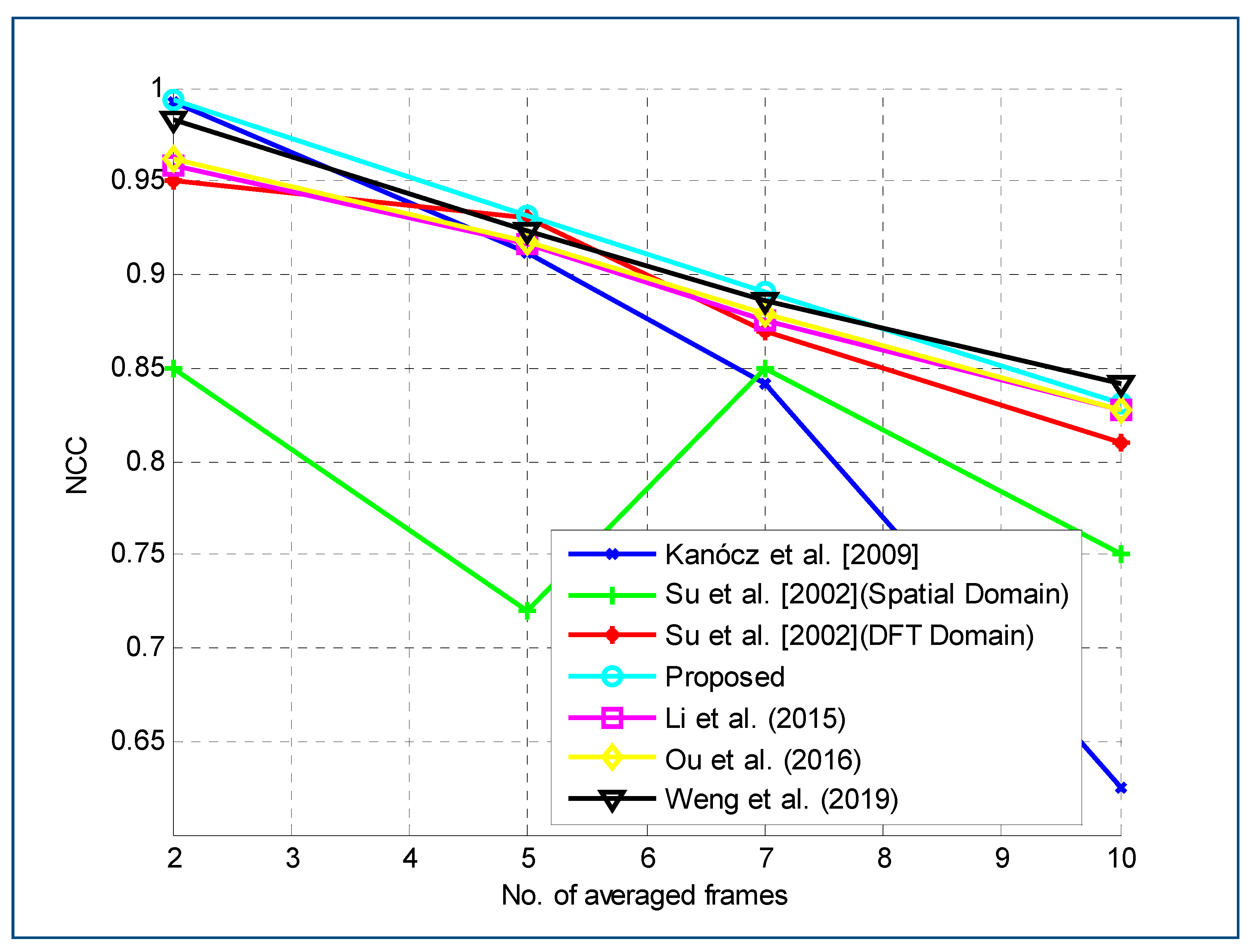
The collusion performance of the proposed method is also compared with previously reported works [
18,
19,
20,
38,
39] to demonstrate the performance comparison. In the time of comparison of our system with the previously proposed ones, we have used reference implementations provided by the authors. It is observed from the results of
Figure 12 that the proposed method offers better gain in term of NCC than the others. This is because the present scheme uses the content dependent watermark to resist the collusion attack. As expected, in
Figure 12, we have seen that as the number of frames being combined increases, the NCC value decreases. It is also seen that there is a dip in the curve for [
38] in
Figure 12. This is due to the fact that in their experimentation, every 5thframe was extracted to form the actual set of test frames. So for every 5thframe, there is a valley in the graph.
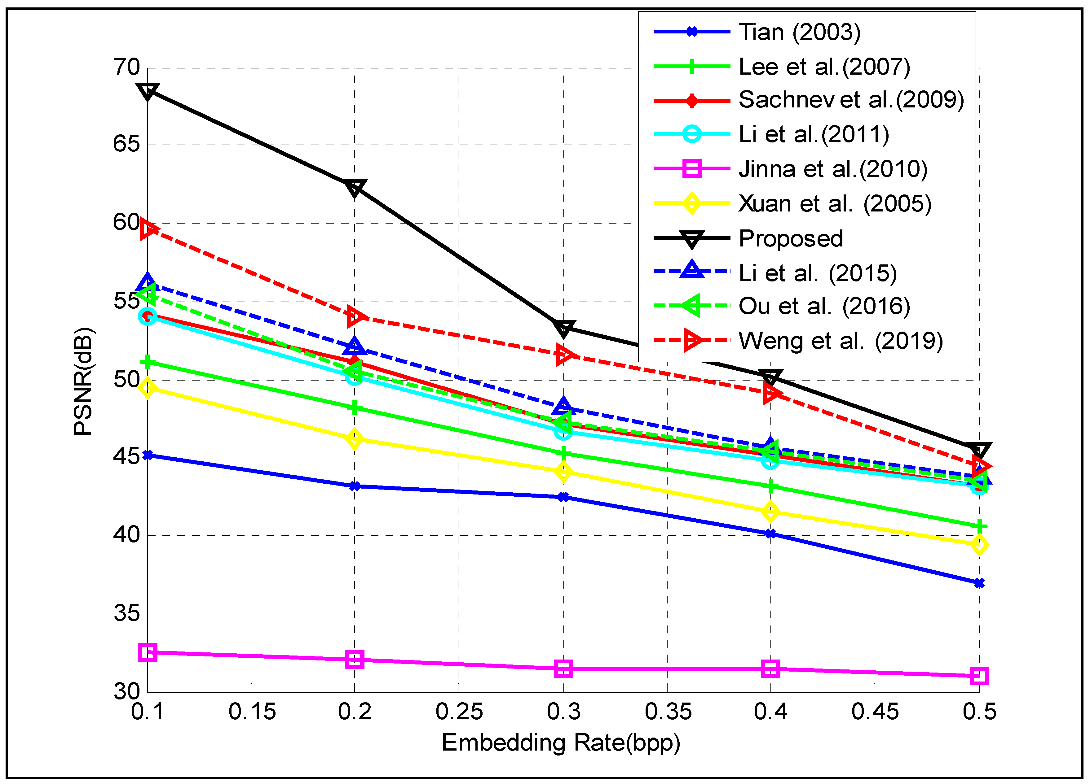
The evaluation performance of the proposed reversible watermarking scheme is compared with the existing related works.
Figure 13 shows the comparative performance in term of embedding capacity (in bpp) versus distortion in PSNR (dB). As expected, with the increase in the embedding capacity (payload), the PSNR (in dB) value decreases. As shown in the figure, the scheme proposed by [
10] offers small PSNR (in dB) compared to other reversible watermarking schemes. In the other schemes, like difference-expansion (DE) proposed by [
9,
11,
12,
13] the tradeoff between capacity and image quality is possible and relatively high PSNR can be achieved. However, as shown in the figure, the proposed scheme offers higher embedding capacity with lower distortion than the other schemes [
18,
19,
20]. This is due to the joint use of lifting and companding technique.
The execution time required to run the whole procedure as a measure of the computational load is also computed. The scheme takes on an average of 1.3543 s. We have also tested the same procedure for traditional DWT. It is seen that the average execution time is 2.1086 s. This result clearly shows that the proposed scheme is much faster than convention DWT based scheme.


