1. Introduction
Interest in cardiovascular biomaterials is primarily driven by the growing prevalence and mortality of cardiovascular disease. Vascular graft technologies, including arterio-venous grafts in hemodialysis access for patients with kidney failure, peripheral artery disease revascularization, and coronary artery bypass grafting (CABG), have a significant clinical impact. CABG procedures neared 400,000 in 2014 [
1]. Although saphenous veins are the most common graft material and are more clinically effective than synthetic grafting with currently available materials, many bypass patients do not have suitable autologous veins for grafting [
2,
3]. Current synthetic grafts in clinical use include expanded polytetrafluoroethylene (ePTFE) and polyethylene terephthalate (Dacron). These materials are desirable for their bioinert and hydrophobic properties. However, they exhibit poor long-term patency rates. Despite the poor long-term results for both ePTFE and Dacron grafting, no new grafting solutions have been approved by the United States Food and Drug Administration pre-market approval process in over 10 years, in large part due to the lack of hemocompatibility of the materials.
An essential criteria for any vascular graft is hemocompatibility to prevent thrombosis, a primary cause of graft failure [
4]. As reviewed previously, the process of biomaterial-induced thrombosis is mediated by the binding of platelets to the rapidly adsorbed proteins on the biomaterial or tissue-engineered surface [
5]. Thrombosis has been particularly well-studied in vitro. For example, many groups have studied biomaterial hemocompatibility using isolated coagulation factors or purified platelets [
6,
7]. More complex systems include using plasma alone or platelet-rich plasma (PRP) in vitro to determine platelet–surface interactions. Although these studies provide important mechanistic insights, a more complete system for studying thrombosis requires whole blood to understand the roles and interactions of the coagulation factors and platelets. Whole blood testing with the ability to control anticoagulant intervention is reflective of the physiological conditions of clinical graft implantations. Therefore, whole blood testing of biomaterials provides a more accurate assessment of the hemocompatibility and of the potential performance in clinical applications [
8].
Our group has used a whole blood, ex vivo shunt model for many decades to evaluate the hemocompatibility of cardiovascular biomaterials [
8,
9,
10,
11,
12,
13]. The ability to control flow rate and local or systemic drugs makes the ex vivo whole blood shunt model very powerful for potential clinical translation. These studies have generated dynamic, quantitative platelet and endpoint fibrin data for numerous biomaterials and experimental drugs. Yet, despite an extensive body of work investigating hemocompatibility of cardiovascular biomaterials and tissue-engineered surfaces, little is understood about the physical properties of the thrombi formed under these ex vivo conditions. The physical thrombus properties are critical to the patency of a vascular graft. However, two-dimensional physical or microscopic inspection, with or without a highly subjective score, is frequently the extent of assessment of the physical parameters of a three-dimensional thrombus [
14,
15]. In order to determine the potential clinical efficacy of novel biomaterials, an improved method for the assessment of graft thrombogenicity under ex vivo conditions is required. The development of such a method will better predict patency and therefore device success or failure.
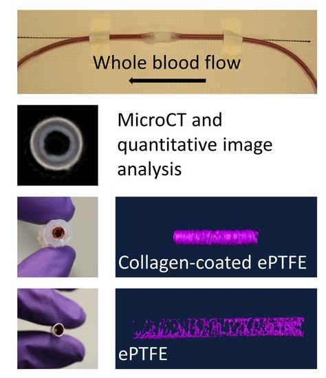
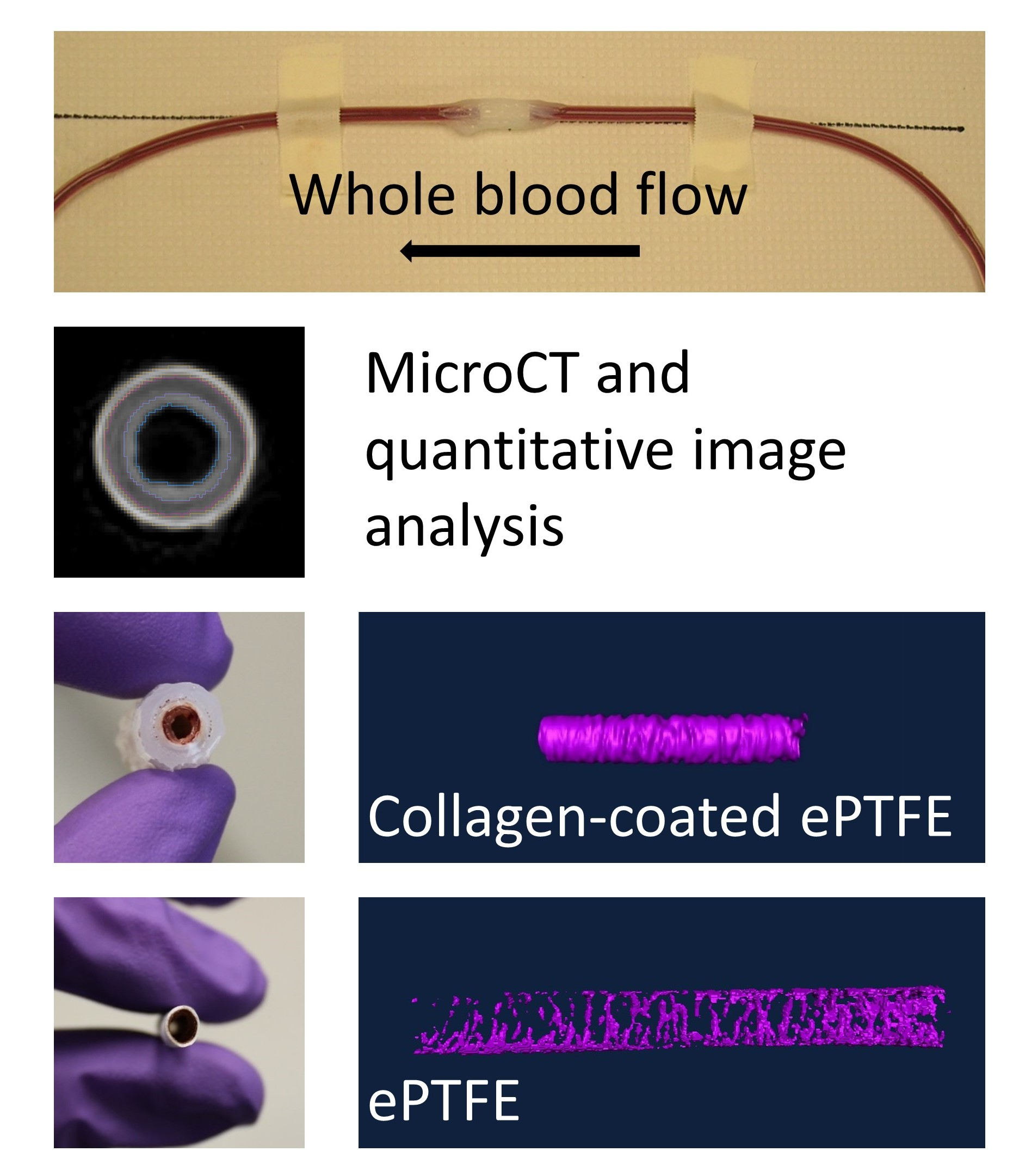
In this study, microcomputed tomography (microCT) imaging was used to analyze thrombus formation in small-diameter vascular grafts formed under flowing whole blood, primarily without antiplatelet therapies, in ex vivo shunt studies. Multiple biomaterials were used to induce a range of sizes of the thrombus. Specifically, ePTFE served as a clinical control; collagen-coated ePTFE acted as a positive, thrombogenic control; and poly(vinyl alcohol) (PVA) served as a preclinical, non-thrombogenic, hydrogel material. Several surface modifications of the PVA, which were previously evaluated for their hemocompatibility and endothelialization potential [
16,
17,
18,
19], were used in this work to assess and validate the measurement of the physical properties of the thrombus. Advanced image software analysis was then used to quantify the luminal volume (the inverse of thrombus volume) and the intra-thrombus variability. We hypothesized that the quantification of platelet and fibrin attachment would inversely correlate to the luminal volume derived using image analysis. That is, an increase in platelets or fibrin would correspond to an increase in thrombus volume and thus decrease in the volume of the lumen. This study quantified the extent of this correlation and developed a novel methodology for providing key quantitative data on the hemocompatibility of cardiovascular biomaterials. These techniques have broader applications to any number of biomaterials or tissue-engineered vascular grafts and have the potential to significantly impact the development of clinical grafts or other cardiovascular devices.
2. Materials and Methods
Overall, to demonstrate this method, multiple biomaterials were used to induce a range of thrombus sizes. The water absorption of the materials necessitated the use of multiple approaches to render the lumen or thrombus radiopaque and quantify the physical properties of the thrombus.
2.1. Device Manufacturing and Preparation
Collagen-coated ePTFE samples served as a positive thrombosis control and were prepared as described previously [
20]. Briefly, the ends of 2 cm segments of ePTFE were attached to silicone tubing (Technical Products, Inc, Oxford, GA, USA) with silicone glue. Additional glue was added to the outer surface of the materials to reinforce the ends. The grafts were covered in heat shrink tubing and the lumen was coated with equine type I collagen (1 mg/mL; Nycomed Arzeneimittel, Munich, Germany) [
21]. Unmodified ePTFE vascular grafts (W.L. Gore) were used as clinical controls (7 cm in length), and were also fabricated in accordance with previous descriptions [
11,
21]. Samples of 3 or 4 cm in length were cut out of the graft after the ex vivo shunt whole blood test to avoid edge effects in the analysis of the thrombus.
Grafts of our preclinical hydrogel (PVA) were manufactured as described previously [
11]. A solution of 10% aqueous PVA (Sigma-Aldrich, 85–124 kDa, 87%–89% hydrolyzed) was combined with 15% (
w/
v) sodium trimetaphosphate (STMP) (Sigma Aldrich) cross-linker and 30% (
w/
v) NaOH. Rods of 4 mm were dip cast to form 4 to 5 mm tubes after delamination. The luminal surfaces were then modified using a variety of techniques, including biochemical and topographical modifications, and assessed for thrombogenesis and hemocompatibility in the ex vivo shunt whole blood test. Specific modifications included integration of the peptide sequence Gly-Phe-Pro-Gly-Glu-Arg (GFPGER), plasma modification, addition of gelatin with a carbonyldiimidazole (CDI) covalent linker, and sterilization, and their preparation methods are described in greater detail in previous publications [
16,
17,
18,
19]. Samples, which were modified by the integration of GFPGER, a peptide subsequence of type I collagen, had GFPGER mixed with the STMP in the PVA manufacturing process [
17]. The luminal surfaces of plasma modification samples were subjected to NH
3 plasma modification using a variation of the radio frequency glow discharge treatment in the presence of NH
3, as described previously [
16,
22]. The PVA for the gelatin-modified samples were activated using CDI with the goal of conjugating a gelatin protein, as described previously [
18]. Additionally, unmodified PVA samples were subjected to terminal sterilization using ethylene oxide (EtO) and gamma radiation after cross-linking and before implantation, as described previously [
19]. Following manufacturing and surface modifications, PVA grafts were assembled for testing by attaching each graft to silicone tubing (Technical Products, Inc.) using heat shrink (Small Parts, Inc.) tubing connectors. Parafilm (Bemis) was used to envelop the connectors to strengthen the junction, as described previously [
11]. Samples of 4 cm in length were cut out of the center of the graft after the ex vivo shunt whole blood test to avoid edge effects in the analysis of the thrombus.
2.2. Whole Blood Testing
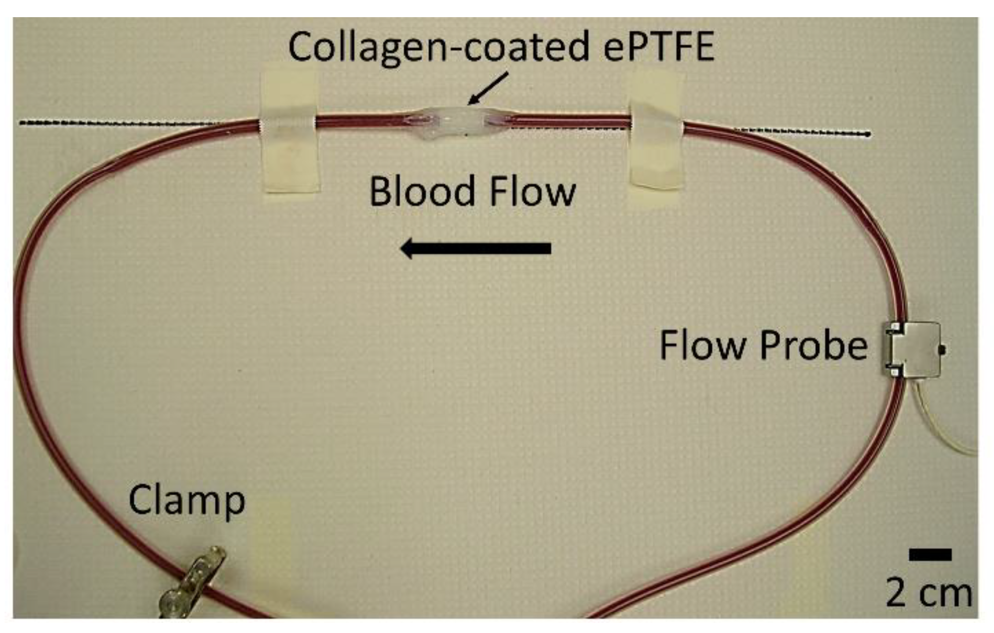
Overall, 110 PVA samples, 26 ePTFE samples, and 20 collagen-coated ePTFE samples were tested and analyzed for this study. All grafts with extended silicone tubing were placed in an ex vivo, baboon, femoral, arteriovenous shunt loop (
Figure 1). Samples were tested in five different animals. For a small subset of samples [
17], acetylsalicylic acid (ASA, Bayer Healthcare) or ASA and clopidogrel (Torrent Pharmaceuticals) was given before experimentation to reduce thrombus formation. Specifically, there were six PVA grafts, three ePTFE grafts, and one collagen-coated ePTFE graft treated with ASA; six PVA grafts, three ePTFE grafts, and one collagen-coated ePTFE grafts were treated with ASA and clopidogrel. ASA was dosed orally at 10 mg/kg at least 4 h before the start of each experiment, and clopidogrel was dosed twice per day orally at 2 mg/kg throughout the length of experimentation. The thrombogenicity of the surface was tested with whole blood containing radiolabeled platelets and fibrin. Platelet and fibrin accumulation were quantified as described previously [
8]. Briefly, indium-111-labeled platelets and iodine-125-labeled fibrin were introduced into the baboons. Platelet deposition was measured throughout the 1-hour study using a gamma camera. Fibrin incorporation was quantified following the total decay (>10 half-lives) of indium-111 [
11]. Juvenile male baboons were cared for according to strict internal and external regulations, which were described in detail previously [
8].
Upon completion of the ex vivo study (whole blood testing), grafts were fixed for subsequent microCT scanning. For ePTFE samples, a larger diameter rigid tubing was added to the exterior of the device to reduce shrinking during fixation. All samples were rinsed with phosphate-buffered saline (PBS) with Ca2+ and Mg2+, and 3.7% paraformaldehyde (PFA) was added. The materials were refrigerated for 24–72 hours to allow for complete fixation. The samples were then rinsed with PBS to remove the PFA. The ePTFE samples were stored in PBS until the day before microCT scanning.
2.3. MicroCT Preparation and Imaging
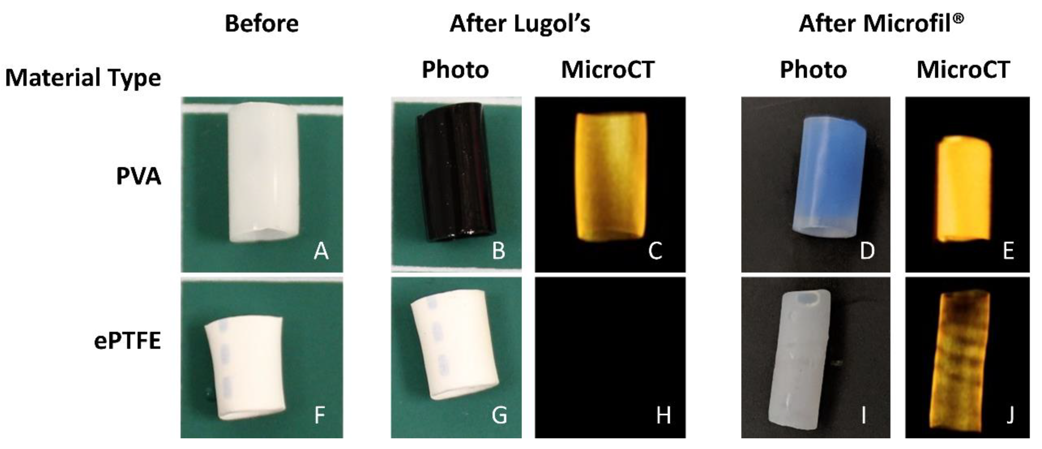
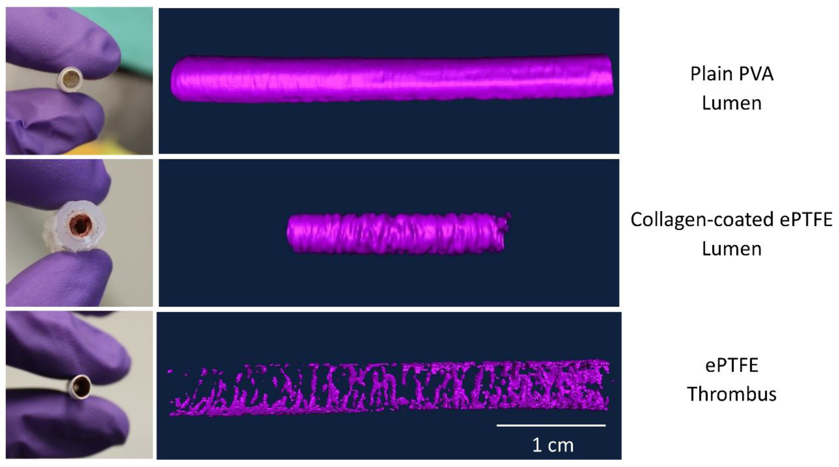
Following fixation, the samples were processed to make either their lumen (PVA) or thrombus (ePTFE, collagen ePTFE) radiopaque for microCT imaging. Each method was evaluated for each of the materials before selecting the methods presented here. Due to the differing material properties of the hydrogel (PVA) and the ePTFE, different methods were used to achieve radiopacity. The lumens of the PVA grafts were filled with Microfil® (Flow Tech, Inc.), which was mixed according to the manufacturer’s instructions. Prior to Microfil® addition, a syringe was used to remove any excess liquid in the grafts. The Microfil® was slowly pipetted into the lumen of the graft with special care taken to avoid air bubbles in the lumen. The Microfil® was cured for 2 hours at room temperature. After curing, the Parafilm and heat-shrink tubing connectors were cut away from the grafts, which were trimmed to their middle 4 cm. PVA samples were stored in PBS until microCT scanning. The thrombus within the ePTFE and collagen-coated ePTFE grafts were rendered radiopaque by soaking in Lugol’s solution (Sigma) for approximately 16 hours prior to microCT imaging.
The grafts were scanned using microCT (Perkins-Elmer, Caliper QuantumFX) with a consistent orientation of the proximal and distal graft ends. Immediately prior to scanning, the glue coating was removed from the collagen-coated ePTFE samples. The samples were centered in the scanner’s field of view using the “Live” mode and built-in stage adjustment. The 2 min (“Fine”) scan was performed using a current of 180 µA, voltage of 90 kV, and 60 mm field of view. With this instrumentation, operated at 30 frames per second (2 × 2 binning, 512 × 512 matrix), there were 3672 acquired projections, which, after four-projection averaging, resulted in 918 projections in the reconstructed image. The exposure time per projection was 0.03327 s. The resultant voxel (117 × 117 × 117µm) images were used for analysis. The sample images ranged from 165–369 slices, depending on the length of the graft. After imaging, sample dimensions (length, outer diameter, inner diameter, and wall thickness) were measured using digital calipers.
2.4. Image Analysis and Processing
To determine the physical characteristics of the thrombi on the basis of the microCT images, the Amira software package (FEI, version 5.2.2) was used by a trained operator, blinded to the specific sample treatment. The software is capable of generating three-dimensional models of the radiopaque regions of each graft, as well as calculating volume and length. Voxel images produced by the microCT scanner were imported into Amira with defined dimensions. Specifically, voxel size was calculated by dividing the field of view (FOV) in millimeters (60 mm in this case) by the voxel quantity (512). After the image was loaded, a label file was created in Amira for each image. Label files allowed for selection of specific regions of interest (ROIs) in each cross-sectional luminal slice of the image. These ROIs were combined into a final volume-rendered surface. A summary of the methods used for the various material types is provided in
Table 1.
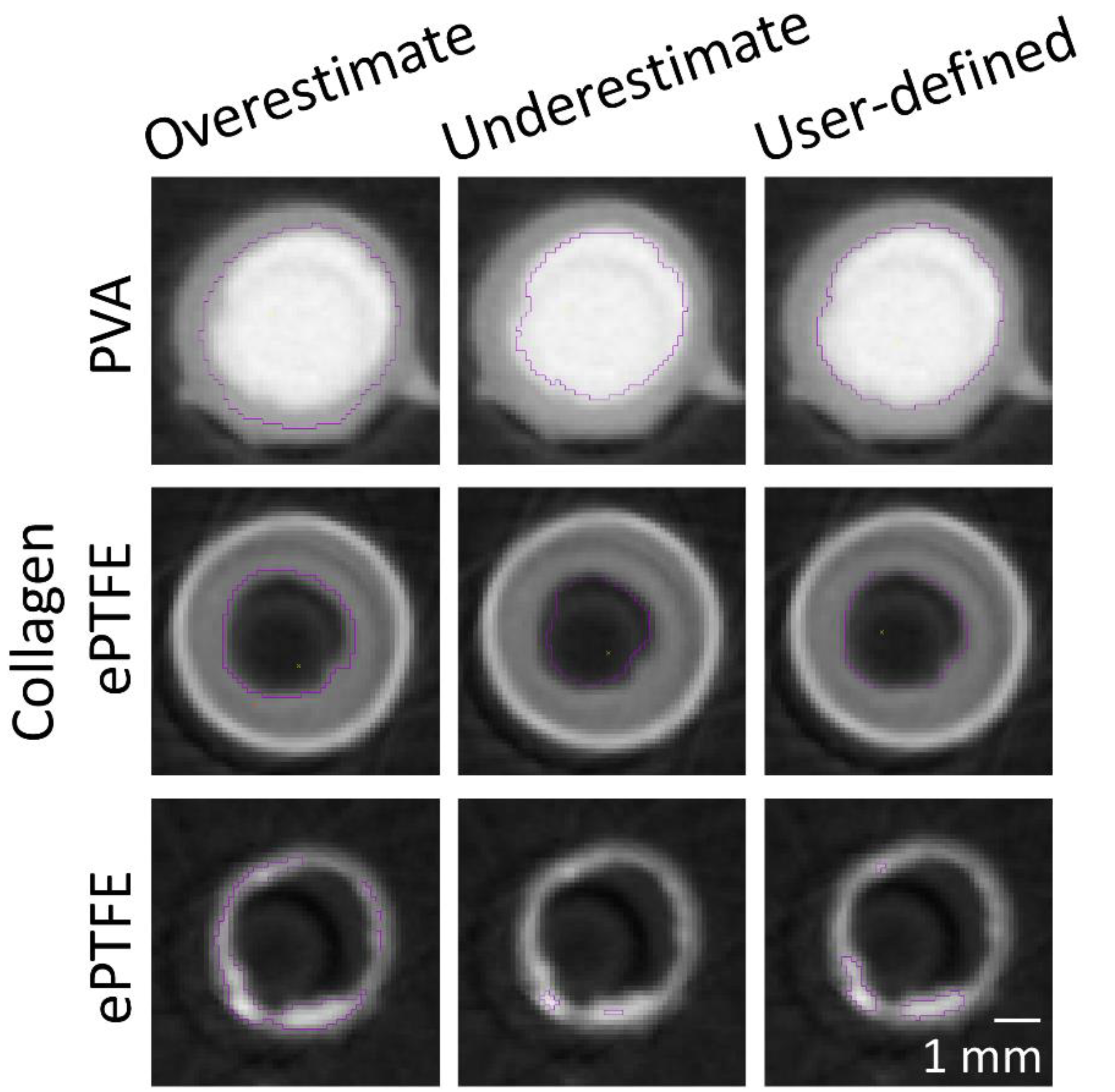
The masking wand within Amira was used to select the ROIs to include all pixels contiguous to the blinded user’s mouse click with intensity within a user-specified range. As the selection of a masking intensity range greatly impacted the final surface volume, standard calibrations were developed to ensure consistency across users and analyses. All masking ranges for PVA samples were selected to include the interior of the bright radiopaque central lumen, as well as one layer of medium gray border pixels on the outside edge (
Figure 2). A similar standard was applied for collagen-coated ePTFE samples, although the interior lumen of these samples was black. For ePTFE samples with or without collagen, the thrombi were rendered radiopaque by their absorption of the Lugol’s solution during the soaking process prior to microCT scanning. These thrombi were then selected as the region of interest in the Amira software by selecting a masking range that included only pixels with the higher intensity.
For PVA samples, the ROI contained the luminal area of the graft in each cross-section. For ePTFE samples, ROIs were selected to contain the thrombi in each cross-section. For the collagen-coated ePTFE samples, multiple ROIs (luminal and thrombus areas) were selected. The Amira imaging software allows the user to select multiple “materials” for a single sample. First, the luminal area for each cross-section was selected similar to the PVA samples. Next, the masking regions were adjusted to select the outermost heat shrink tubing as a new material. Then, the ePTFE was selected. Finally, the remaining material, which was the thrombus, was selected (
Figure 3).
The luminal volumes for PVA and collagen-coated ePTFE samples were directly quantified using selective pixel intensity masking in the Amira software. For ePTFE samples, luminal volume was calculated by subtracting the thrombus volume quantified in the Amira software from a volume calculated using a cylindrical approximation on the basis of caliper measurements. For all samples, the luminal volume was then used to calculate the average luminal area through length normalization based on the Amira-measured length; thus, results are presented as average luminal volume per length, or average cross-sectional area.
After ROIs were selected for all cross-sections, the length of the resultant surface was obtained using Amira’s slice-numbering system. The cross-sectional ROIs were then combined using Amira’s “SurfaceGen” feature to yield a three-dimensional representation of either the lumen (PVA, collagen ePTFE) or the thrombus (ePTFE, collagen ePTFE) of the graft. The areas of these surfaces within a slice were then measured using Amira’s “SurfaceArea” tool. To gain a more detailed understanding of the thrombus geometry over the entire graft surface, samples were examined on the basis of each cross-sectional slice datum, as imaged by the microCT and generated by the Amira software. The the cross-sectional thrombus and luminal areas over the entire length were exported into a table using Amira’s “AreaPerSlice” tool.
2.5. Implant Testing
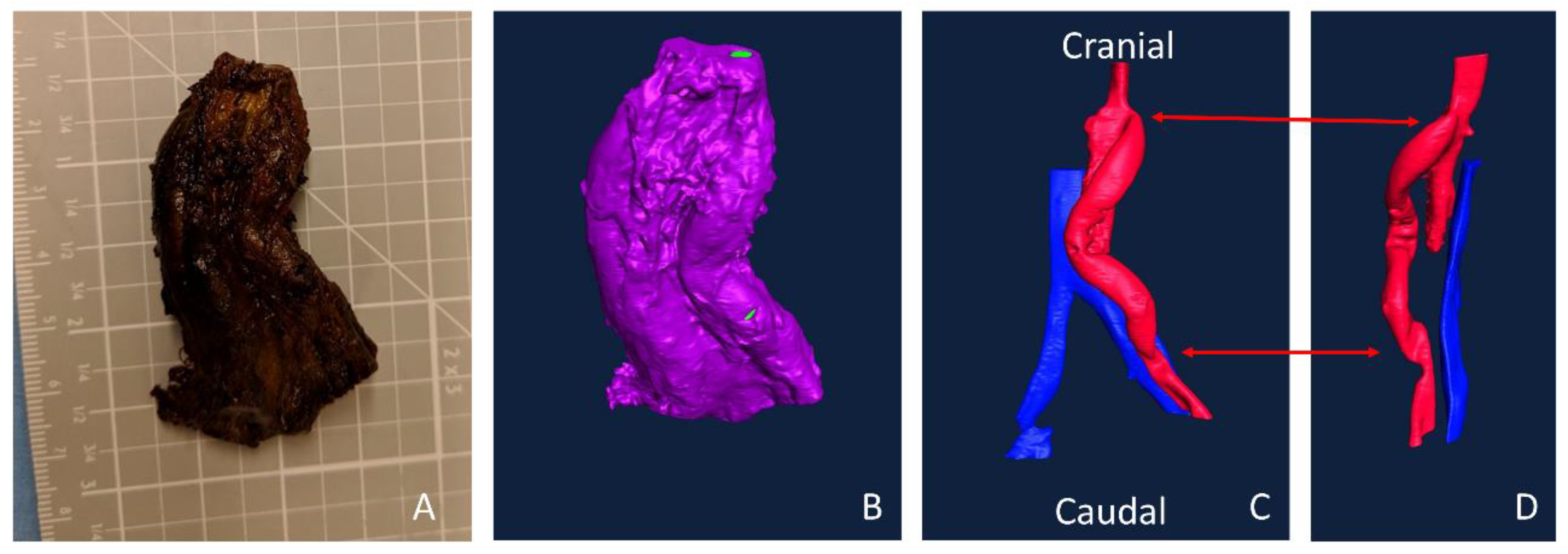
These methods were applied in a single implant study in a single animal. An aortoiliac bypass study was performed as described previously, according to the ‘‘Guide for the Care and Use of Laboratory Animals’’ prepared by the Committee on Care and Use of Laboratory Animals of the Institute of Laboratory Animal Resources, National Research Council, with approval by the Institutional Animal Care and Use Committee [
8,
23]. In brief, PVA and ePTFE grafts were implanted bilaterally from the aorta of a male, juvenile baboon to the iliac artery using end-to-side anastomoses. After 28 days, samples were explanted, fixed for several days, and soaked in Lugol’s solution overnight. The sample was imaged with the MicroCT and imported into Amira as described above. Because all the tissue was rendered radiopaque by the Lugol’s, the open areas were selected to illustrate the lumens of the vessels and graft. Multiple “materials” were selected to segment arterial or venous flow.
2.6. Statistics
The average luminal cross-sectional area (volume/length) was correlated to the platelet (per unit graft length) end point data and fibrin end point data using SPSS (IBM, Version 24.0.0.0). R2 values were calculated for each material type (collagen ePTFE, ePTFE, and PVA), and an ANOVA was used to determine if the correlation was significant (p < 0.05).
4. Discussion
This work presents a broadly applicable technique for quantifying the physical characteristics of biomaterial-induced thrombosis, which can translate to an improved understanding of clinical patency for cardiovascular device development. Thrombosis research is typically limited to specific clotting characteristics (e.g., platelet attachment, FXa (activated factor X) generation), but even when fresh, flowing, whole blood is used, little emphasis has been given to the physical characteristics of the formed thrombus beyond basic observation. These thrombus characteristics can dictate the percent stenosis and ultimately the success or failure of the device. This approach addresses the limited understanding of physical thrombus characteristics in vascular grafts with a variety of biomaterials.
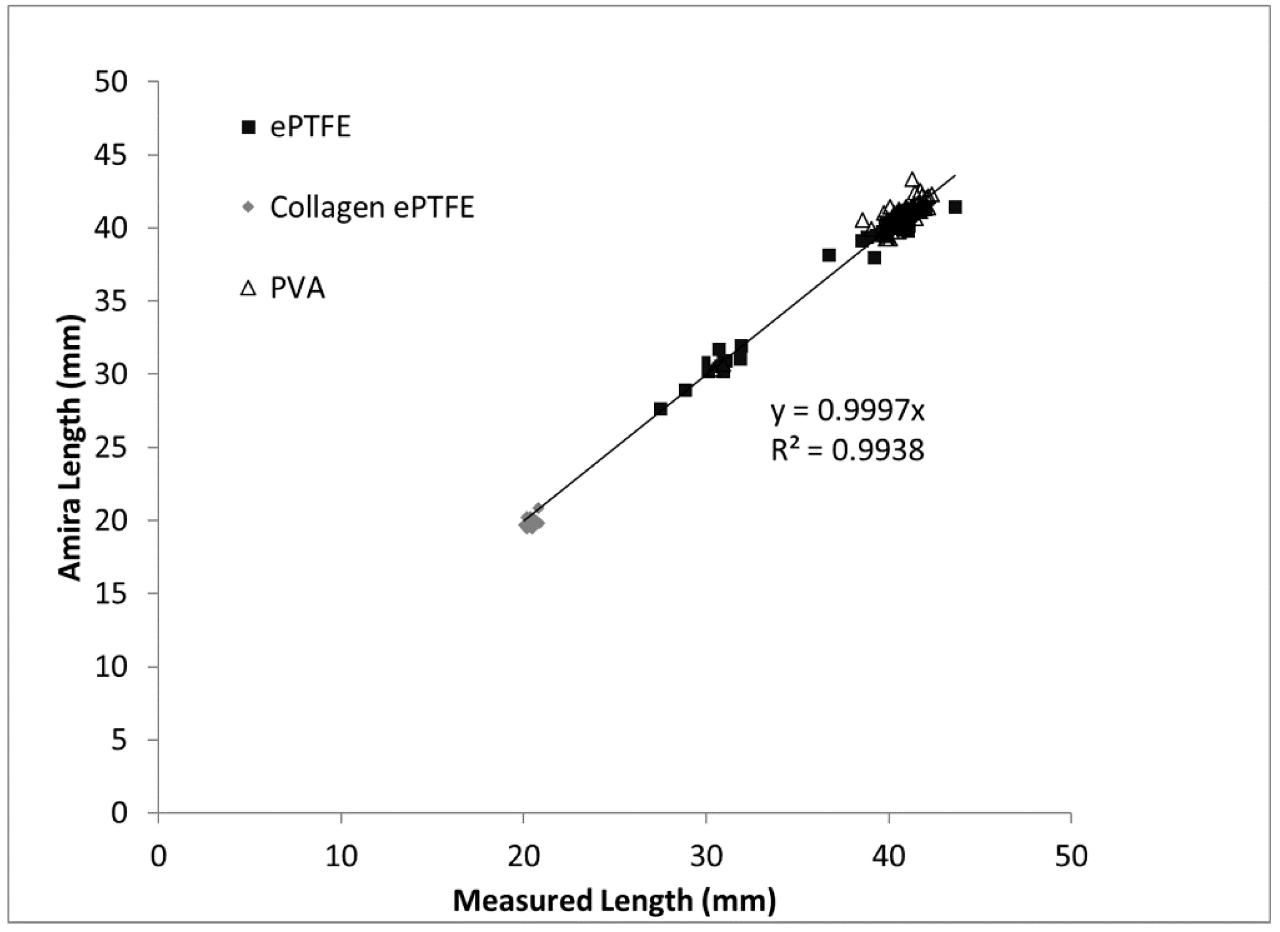
The goal of this study was to improve upon existing methods for assessing the thrombogenicity of cardiovascular materials by developing and validating an imaging-based method that provides detailed information about the physical parameters and gross morphology of thrombi formed under flowing whole blood. The thrombus volume data obtained by applying the microCT and image analysis method to a large combination of biomaterials, surface modifications, and systemic therapeutics indicate the technique’s broad applicability. The correlation of the measured thrombus volumes to the existing platelet and fibrin amounts supports the accuracy of the method. Among the validating metrics presented in this study are the comparison of the Amira-measured graft lengths to the caliper-measured lengths. As would be expected, the length measurements exhibited a near-perfect one-to-one correspondence, with a strong statistical correlation and a trendline slope of almost exactly one. Therefore, on the basis of the results of the study, a novel methodology has been developed to provide key quantitative metrics of the formation of thrombi on blood-contacting biomaterials under flow.
The developed method included distinct material processing techniques for different biomaterials, selected on the basis of their material properties. The overall goal was to generate differences in radiopacity between the lumen, the thrombus, and the biomaterial. This contrast between lumen and thrombus in the microCT images was necessary for the subsequent detection and quantification by the image analysis software. In this study, hydrogels (PVA) and non-woven meshes (ePTFE) were tested. However, these techniques can be translated to a vast array of biomaterials. For example, the technique of soaking materials in aqueous Lugol’s solution can be extended to other hydrophobic materials. Although the hydrophilicity of PVA caused equivalent uptake of Lugol’s solution by both the thrombus and the graft biomaterial, perfusing the lumen with Microfil
® enabled a clear distinction of the lumen. Therefore, this use of Microfil
® provides a material processing technique that can be translated to other hydrogels and nonporous materials [
24].
The materials tested during the development of this method span the spectrum of thrombogenicity, from low platelet attachment (as low as 0.003 billion platelets per mm) on some PVA grafts, up to 0.28 billion platelets per millimeter of graft length on collagen-coated ePTFE after 60 min exposure to whole blood. This large range of responses was designed into the study by using multiple materials, testing with and without antiplatelet therapies, and using multiple surface modifications of the PVA. The various PVA modifications were not illustrated in the current work to compare their effects, but rather were merged into a single dataset to generate a broad response range. Overall, this broad response suggests the usefulness of this technique to quantify the physical parameters of the thrombus, which can be applied to materials with a varying degree of hemocompatibility. Because platelets and fibrin are key components of thrombi formed under flow, the measured elevated amounts of platelets and fibrin on the graft surfaces during the whole blood testing indicate the formation of a thrombus, and a resultant reduction in luminal area. Therefore, the negative slope of the correlations between luminal area and platelet accumulation on the PVA and collagen-coated ePTFE grafts provides a particularly strong validation of this technique (
Figure 8). It is notable, however, that the comparison of the luminal area of collagen-coated ePTFE grafts with fibrin accumulation did not demonstrate a significant correlation (
Figure 8;
R2 = 0.039,
p = 0.402,
F = 0.737). This may have been due to the orientation of the hydroxyl groups in the fibrinogen protein, which render it more likely to interact with PVA surfaces than collagen-coated ePTFE surfaces [
24,
25]. Importantly, these whole blood experiments occurred under an arterial flow rate, which tends to lead to the formation of more platelet-rich thrombi. In contrast, thrombi formed under venous flow tend to contain higher fibrin quantities [
26,
27,
28]. The application and correlation of this method of thrombus quantification to platelet and fibrin accumulation remains to be performed under venous flow conditions.
The application of an imaging-based method to the measurement of thrombus formation on relatively non-thrombogenic cardiovascular biomaterials presents broader challenges. This was demonstrated in this study’s finding of a relatively weak correlation between the resultant luminal area and the platelet and fibrin attachment measured on ePTFE grafts (
Figure 8). The PVA (with a broad range of responses due to the numerous surface modifications) and collagen-coated ePTFE (inherently prothrombogenic) biomaterials had strong correlations with an increase in platelet and fibrin accumulation, indicating a decrease in average luminal area. In contrast, the average luminal area in ePTFE samples did not change dramatically across a broad range of platelet and fibrin attachment, leading to the lack of correlation. Although this weak correlation could be attributed to a greater platelet and fibrin composition in the ePTFE thrombus without as much of an effect on the luminal area, the relative inefficacy of the method as applied to non-collagen coated ePTFE grafts is hypothesized to be caused by the limited ability of the user to distinguish small differences in pixel intensity when a low quantity of pixels is present, as in the ePTFE with low thrombogenicity. In order to determine if the unchanged luminal area is due to thrombus composition or a limitation in resolving small thrombus areas, future experiments could adopt a longer whole blood testing study period. Additionally, different microCT instrumentation with higher resolution would enable the quantification of smaller thrombi or thrombi in smaller diameter grafts. Indeed, we have been successful at translating these protocols and image analysis method to an alternative microCT system, and anticipate that researchers could use any microCT imaging system that this available to them. Additionally, alternative contrast agents, such as nanoparticles [
29], may improve feature detection and improve image segmentation.
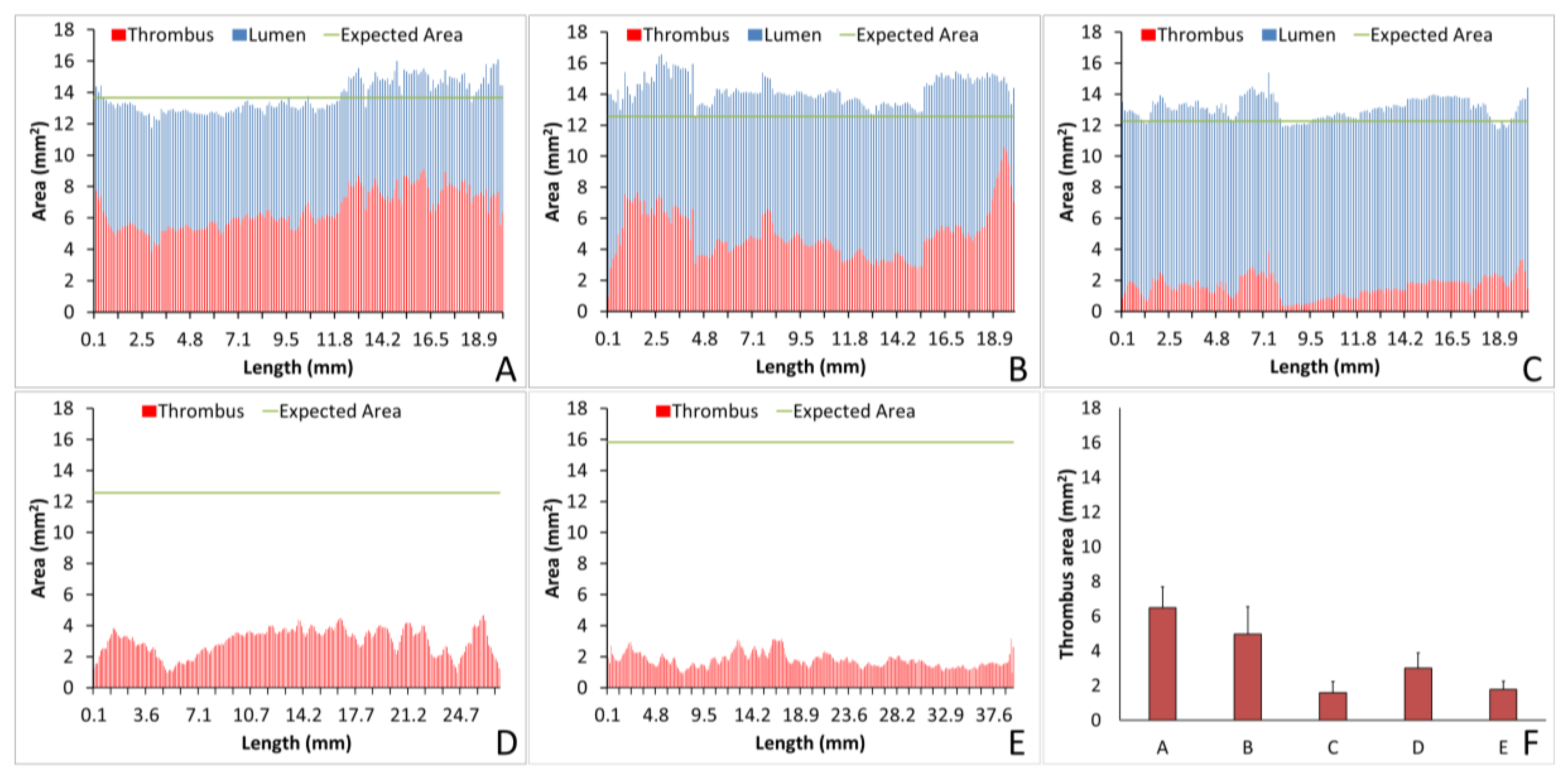
The analysis of individual thrombi on grafts can provide valuable information on the hemocompatibility of biomaterials. Using Amira, we were able to quantify the lumen or thrombus cross-sectional area per slice, enabling analysis of the thrombus formation at all points throughout the graft and a quantification of the thrombus variability across the graft length. For example, for the collagen-coated ePTFE grafts tested under no anticoagulant and ASA alone, the average thrombus areas were equivalent, as shown in
Figure 7A,B, respectively. Importantly, however, the ASA treated study resulted in an increased variability of cross-sectional thrombus volume per slice. Physiologically, this could predispose the thrombus to embolization. Although the data presented here only display a representative image and a full analysis is beyond the scope of presenting this method, future work will examine the variability and the compare distributions between various samples. In addition to improving the understanding of biomaterial hemocompatibility in the well-established and well-controlled arteriovenous, whole blood, shunt model, these methods illustrate the potential of applying this method to a more complex in vivo, end-to-side implant model. Although the occluded sample could not be visualized with this technique, the patent side was well illustrated. Using non-destructive imaging at this length scale allows for an increased understanding of the path of the blood flow and the patency of the implanted graft along its length and particularly at the critical points of healing, the anastomoses. The sample tested here did suggest some narrowing at the anastomoses. This imaging could be combined with the more destructive histological process to quantify the intimal hyperplasia at the anastomoses [
8]. Thus, these methods could be used to characterize both the hemocompatibility of biomaterials, as well as the healing responses, therefore identifying where biomaterials fail.
The methods developed in this study do have some limitations. The specific equipment (microCT scanner and Amira software) require a significant financial investment, and the training of Amira program users to accurately determine pixel masking ranges is time-intensive. However, the methods developed and presented in this study provide novel, validated techniques for the measurement of the physical parameters of thrombi formed on blood-contacting materials under flow. Applications of this technique to future work could include its extension to the hemocompatibility of biomaterials under venous blood flow conditions, and to the development of novel cardiovascular biomaterials and tissue-engineered implants. Given the well-established importance of assessing biomaterial thrombogenicity prior to clinical implementation, the introduction of this methodology provides a powerful tool for the development of blood-contacting biomaterials and tissue-engineered implants.


