
Mechanical Properties of Re-Entrant Hybrid Honeycomb Structures for Morphing Wings


Abstract
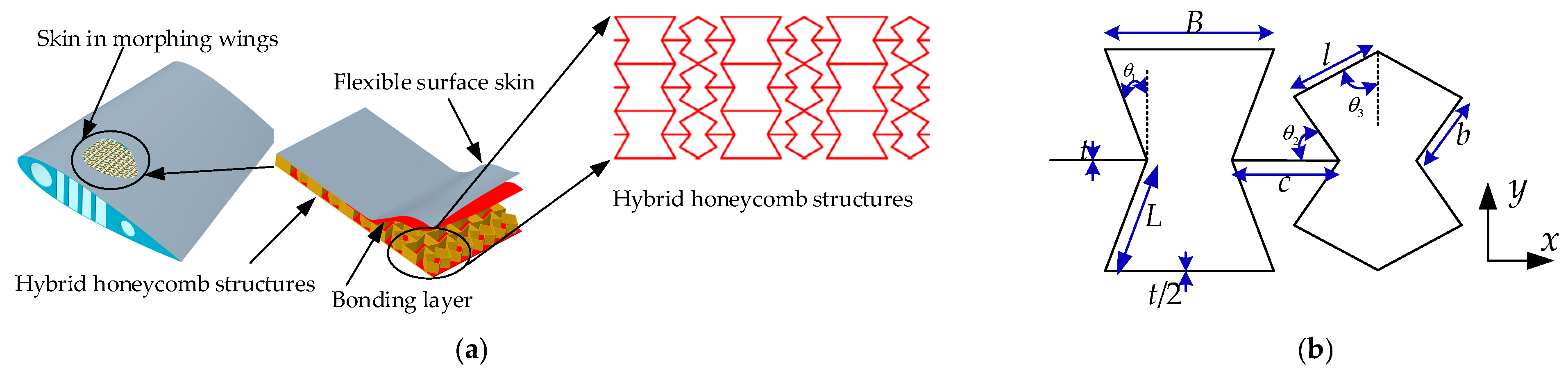
1. Introduction
2. Theoretical Analysis Model
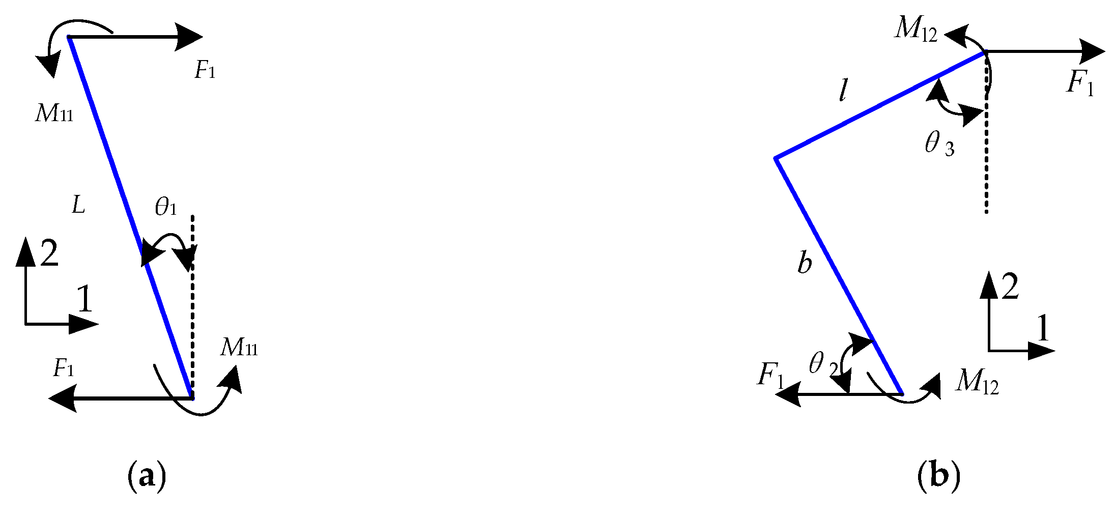
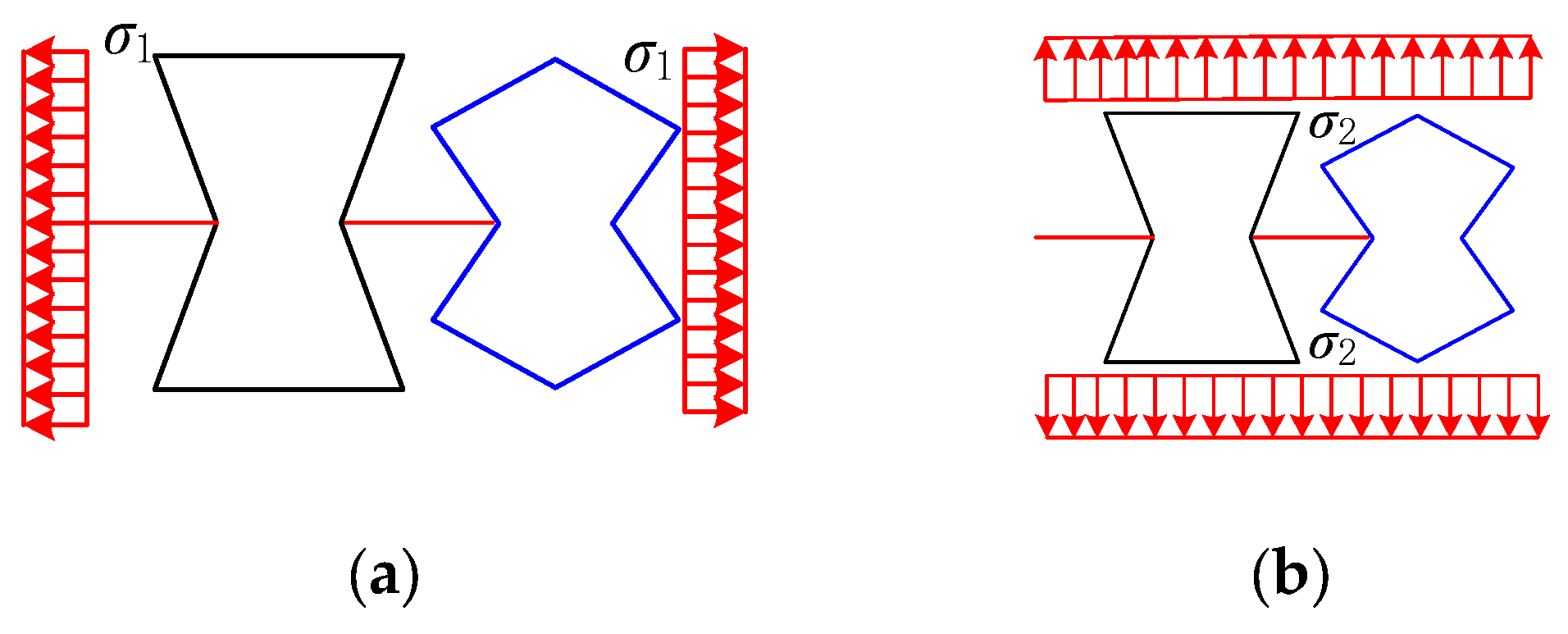
2.1. Single-Cell x-Direction Stretching
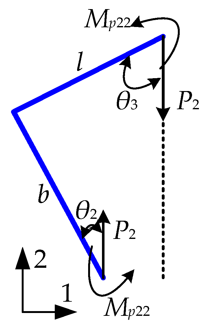
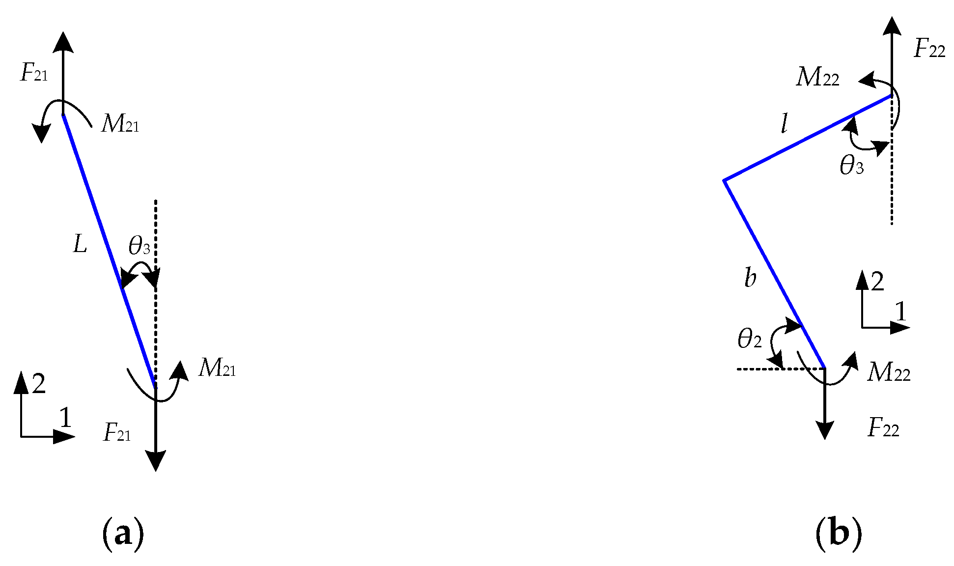
2.2. Single-Cell y-Direction Stretching
2.3. Hybrid Honeycomb Structure Elastic Modulus and Poisson’s Ratio
3. Finite Element Analysis (FEA) and Experiment
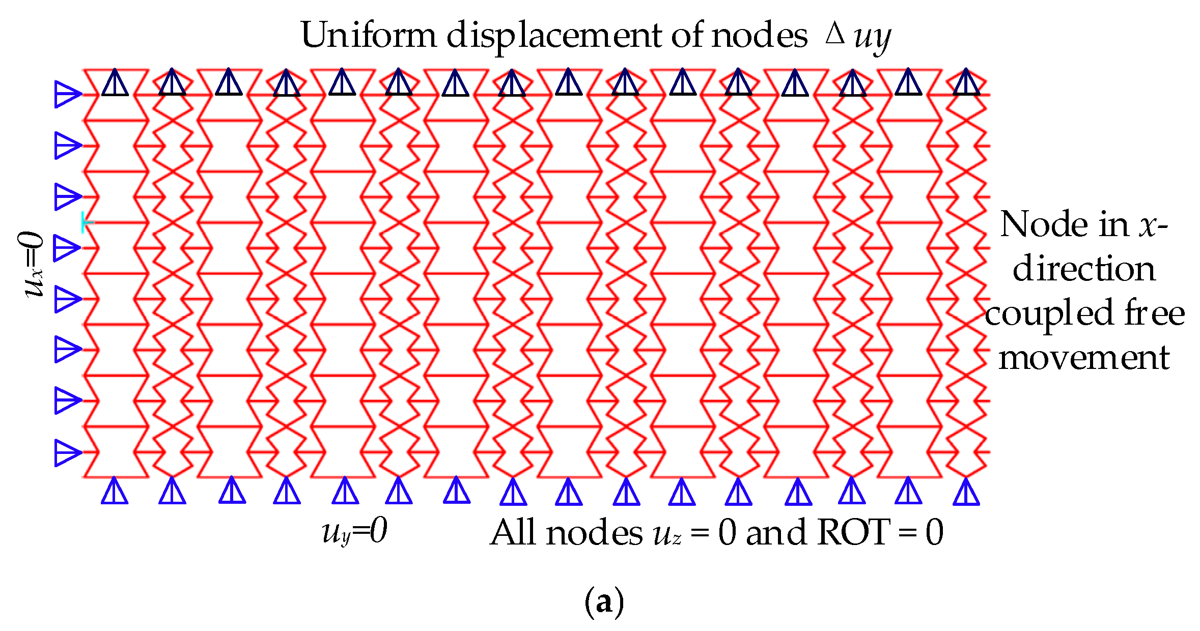
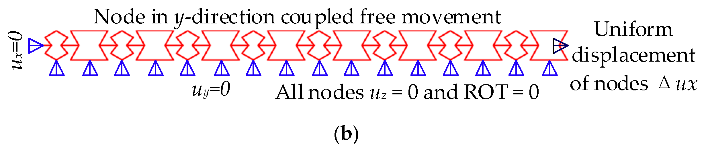
3.1. Finite Element Analysis Section
3.2. Experiments
4. Discussion
4.1. Effect of Parameter θ2 on Cell Structure
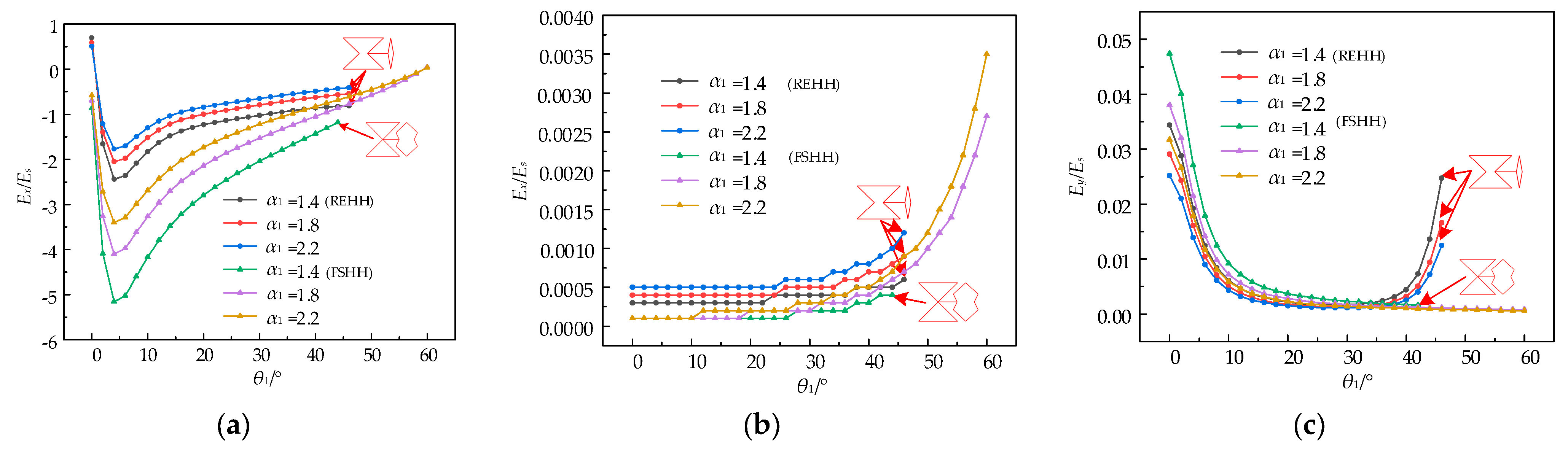
4.2. Effect of Parameters α1 and α2 on Cell Structure
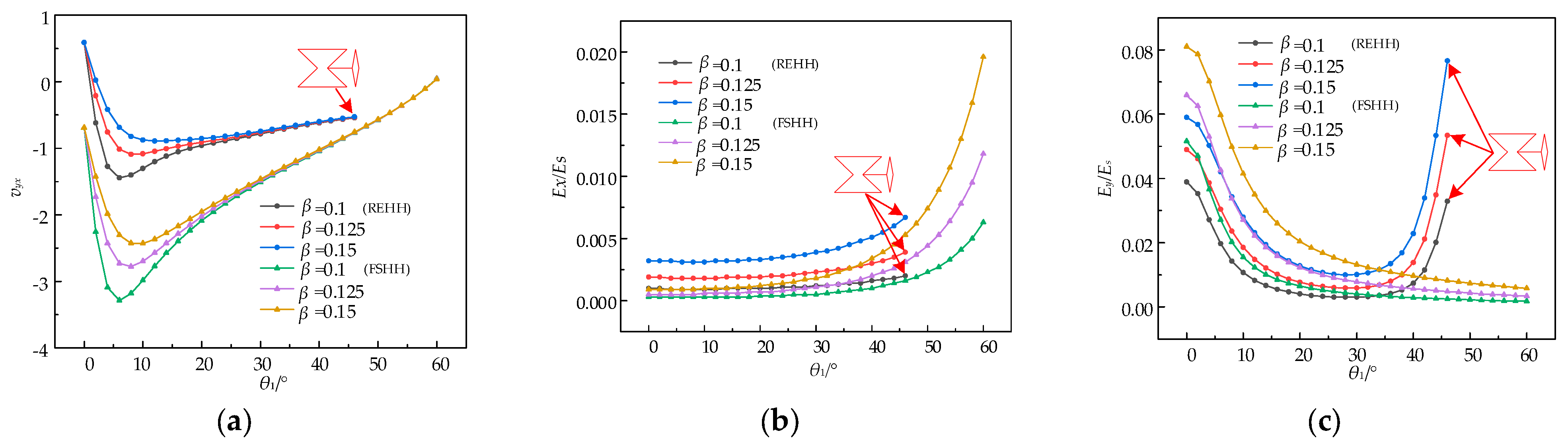
4.3. Effect of Parameter on Cell Structure
5. Conclusions
- (1)
- The theoretical models of the elastic modulus Ex/Es, Ey/Es, and Poisson’s ratio vyx of the REHH structures were developed based on the Euler–Bernoulli beam model and Castigliano’s second theorem. The relative errors in the relative elastic modulus Ex/Es and Ey/Es, as well as Poisson’s ratio vyx between the simulation and theoretical results were no more than 7.03%, 9.5%, and −8.78%.
- (2)
- The two samples of the REHH structures were fabricated using 3D printing technology, and an experimental setup was established for conducting a tensile test. The relative errors between the experimental and theoretical results of the relative elastic modulus Ex/Es and Ey/Es, as well as Poisson’s ratio vyx were no more than 0.63%, 7.4%, and 8.75%, thereby validating the accuracy of the theoretical and simulated models.
- (3)
- Parametric studies reveal that the mechanical properties of the REHH structures exhibit a similar trend to the former FSHH structures as with the vertex angle θ1 of the concave hexagon increasing. The size ratio Ex/Es of the REHH structures is typically smaller, while Ey/Es is generally larger, with no significant disparity between them. However, in terms of NPR properties, the REHH structures demonstrate remarkable superiority compared to the FSHH structures. The parameters of the cell elements can be adjusted to achieve tuneable tensile properties.
Author Contributions
Funding
Institutional Review Board Statement
Data Availability Statement
Conflicts of Interest
References
- Heo, H.; Ju, J.; Kim, D.M.; Jeon, C.S. Passive morphing airfoil with honeycombs. In Proceedings of the ASME 2011 International Mechanical Engineering Congress and Exposition, Denver, CO, USA, 11–17 November 2011; pp. 263–271. [Google Scholar]
- Spadoni, A.; Ruzzene, M. Static aeroelastic response of chiral-core airfoils. J. Intell. Mater. Syst. Struct. 2007, 18, 1067–1075. [Google Scholar] [CrossRef]
- Easey, N.; Chuprynyuk, D.; Musa, W.S.; Bangs, A.; Dobah, Y.; Shterenlikht, A.; Scarpa, F. Dome-shape auxetic cellular metamaterials: Manufacturing, modeling, and testing. Front. Mater. 2019, 6, 86. [Google Scholar] [CrossRef]
- Chiang, Y.C.; Mostafavi, S.; Bier, H. Assembly of shells with bi-stable mechanism. In Advances in Architectural Geometry; Chalmers University of Technology: Gothenburg, Sweden, 2018; pp. 54–71. [Google Scholar]
- Liu, J.Y.; Guo, H.B.; Wang, T. A review of acoustic metamaterials and phononic crystals. Crystals 2020, 10, 305. [Google Scholar] [CrossRef]
- Balan, P.M.; Mertens, A.J.; Bahubalendruni, M.V.A.R. Auxetic mechanical metamaterials and their futuristic developments: A state-of-art review. Mater. Today Commun. 2023, 34, 105285. [Google Scholar] [CrossRef]
- Nicolaou, Z.G.; Motter, A.E. Mechanical metamaterials with negative compressibility transitions. Nat. Mater. 2012, 11, 608–613. [Google Scholar] [CrossRef] [PubMed]
- Yang, H.; Jiang, S.C.; Wang, Y.; Xiao, H. Fluid-Structure Coupling and Aerodynamic Performance of a Multi-Dimensional Morphing Wing with Flexible Metastructure Skin. Aerospace 2023, 10, 678. [Google Scholar] [CrossRef]
- Olympio, K.R.; Gandhi, F. Zero Poisson’s Ratio Cellular Honeycombs for Flex Skins Undergoing One-Dimensional Morphing. SAGE J. 2010, 21, 1737–1753. [Google Scholar] [CrossRef]
- Alsaidi, B.; Joe, W.Y.; Akbar, M. Computational Analysis of 3D Lattice Structures for Skin in Real-Scale Camber Morphing Aircraf. Aerospace 2019, 6, 79. [Google Scholar] [CrossRef]
- Alvarez-Trejo, A.; Cuan-Urquizo, E.; Bhate, D.; Roman-Flores, A. Mechanical metamaterials with topologies based on curved elements: An overview of design, additive manufacturing and mechanical properties. Mater. Des. 2023, 233, 112190. [Google Scholar] [CrossRef]
- Xue, H.P.; Luo, Z.; Brown, T.; Beier, S. Design of Self-Expanding Auxetic Stents Using Topology Optimization. Front. Bioeng. Biotechnol. 2020, 8, 736. [Google Scholar] [CrossRef] [PubMed]
- Liu, T.Z.; Zhang, Y.L.; Yang, J.L.; Cai, J.G. Composite negative stiffness structure with tunable and temperature-dependent properties induced by viscoelastic and shape-memory materials. Compos. Commun. 2024, 48, 101937. [Google Scholar] [CrossRef]
- Jopek, H. Finite Element Analysis of Tunable Composite Tubes Reinforced with Auxetic Structures. Materials 2018, 10, 1359. [Google Scholar] [CrossRef]
- Mustahsan, F.; Khan, S.Z.; Zaidi, A.A.; Alahmadi, Y.H. Re-entrant honeycomb auxetic structure with enhanced directional properties. Materials 2022, 15, 8022. [Google Scholar] [CrossRef] [PubMed]
- Ma, F.; Wang, C.; Liu, C.; Wu, J. Structural designs, principles, and applications of thin-walled membrane and plate-type acoustic/elastic metamaterials. J. Appl. Phys. 2021, 129, 231103. [Google Scholar] [CrossRef]
- Wang, T.; Li, Z.; Wang, L.; Hulbert, G. Crashworthiness analysis and collaborative optimization design for a novel crash-box with re-entrant auxetic core. Struct. Multidiscip. Optim. 2020, 62, 2167–2179. [Google Scholar] [CrossRef]
- Peng, X.L.; Bargmann, S. Nacre-inspired auxetic interlocking brick-and-mortar composites. Compos. Commun. 2024, 48, 101892. [Google Scholar] [CrossRef]
- Lu, Z.; Li, X.; Yang, Z.; Xie, F. Novel structure with negative Poisson’s ratio and enhanced Young’s modulus. Compos. Struct. 2016, 138, 243–252. [Google Scholar] [CrossRef]
- Fu, M.; Chen, Y.; Hu, L. A novel auxetic honeycomb with enhanced in-plane stiffness and buckling strength. Aerosp. Sci. Technol. 2017, 160, 574–585. [Google Scholar] [CrossRef]
- Fu, M.; Chen, Y.; Hu, L. Bilinear elastic characteristic of enhanced auxetic honeycombs. Compos. Struct. 2017, 175, 101–110. [Google Scholar] [CrossRef]
- Xu, M.; Liu, D.; Wang, P.; Zhang, Z.; Jia, H.; Lei, H.; Fang, D. In-plane compression behavior of hybrid honeycomb meta-structures: Theoretical and experimental studies. Aerosp. Sci. Technol. 2020, 106, 106081. [Google Scholar] [CrossRef]
- Xiao, C.D.; Tian, R.L.; Zhang, X.L.; Li, S. Variable stiffness and zero Poisson’s ratio of the butterfly-shaped mechanical metamaterial. Compos. Commun. 2024, 49, 101958. [Google Scholar] [CrossRef]
- Shen, J.; Zhou, S.; Huang, X.; Xie, Y. Simple cubic three-dimensional auxetic metamaterials. Phys. Status Solidi 2014, 251, 1515–1522. [Google Scholar] [CrossRef]
- Lim, T.C. A 3D auxetic material based on intersecting double arrowheads. Phys. Status Solidi 2016, 253, 1252–1260. [Google Scholar] [CrossRef]
- Nugroho, W.T.; Dong, Y.; Pramanik, A.; Selvan, M.C.P.; Zhang, Z.; Ramakrishna, S. Additive manufacturing of re-entrant structures: Well-tailored structures, unique properties, modelling approaches and real applications. Addit. Manuf. 2023, 78, 103. [Google Scholar] [CrossRef]
- Khan, S.Z.; Masood, S.H.; Cottam, R. Mechanical properties of a novel plymetal manufactured by laser-assisted direct metal deposition. Int. J. Adv. Manuf. Technol. 2017, 91, 1839–1849. [Google Scholar] [CrossRef]


| Ex/Es | Ey/Es | vyx | |||||||
|---|---|---|---|---|---|---|---|---|---|
| θ1 | Theoretical Results | Simulated Results | REs/% | Theoretical Results | Simulated Results | REs/% | Theoretical Results | Simulated Results | REs/% |
| 10° | 0.0000357 | 0.0000384 | 7.03 | 0.0023 | 0.00216 | −6.48 | −3.91 | −4.2 | −7.43 |
| 20° | 0.000045 | 0.0000485 | 6.44 | 0.0008 | 0.000748 | −6.95 | −2.18 | −2.39 | −8.78 |
| 30° | 0.0000691 | 0.000072 | 4.02 | 0.0005 | 0.000476 | −5.04 | −1.44 | −1.54 | −6.94 |
| 40° | 0.000128 | 0.000134 | 4.68 | 0.0004 | 0.000425 | 5.88 | −0.99 | −1.07 | −7.47 |
| 50° | 0.000292 | 0.000305 | 4.2 | 0.0003 | 0.000328 | 8.53 | −0.57 | −0.62 | −8.06 |
| 60° | 0.000824 | 0.000883 | 6.68 | 0.0002 | 0.000221 | 9.5 | 0.0458 | 0.043 | −6.51 |
| Simulated Results | Experimental Results | REs/% | |
|---|---|---|---|
| Ex/Es | 0.0005366 | 0.0005403 | 0.63 |
| Ey/Es | 0.00261 | 0.00248 | 7.4 |
| vyx | −1.416 | −1.54 | 8.75 |
Disclaimer/Publisher’s Note: The statements, opinions and data contained in all publications are solely those of the individual author(s) and contributor(s) and not of MDPI and/or the editor(s). MDPI and/or the editor(s) disclaim responsibility for any injury to people or property resulting from any ideas, methods, instructions or products referred to in the content. |
© 2024 by the authors. Licensee MDPI, Basel, Switzerland. This article is an open access article distributed under the terms and conditions of the Creative Commons Attribution (CC BY) license (https://creativecommons.org/licenses/by/4.0/).
Share and Cite
Wang, Y.; Guo, Y.; Yang, H. Mechanical Properties of Re-Entrant Hybrid Honeycomb Structures for Morphing Wings. Biomimetics 2024, 9, 521. https://doi.org/10.3390/biomimetics9090521
Wang Y, Guo Y, Yang H. Mechanical Properties of Re-Entrant Hybrid Honeycomb Structures for Morphing Wings. Biomimetics. 2024; 9(9):521. https://doi.org/10.3390/biomimetics9090521
Chicago/Turabian StyleWang, Yan, Yingjie Guo, and Hui Yang. 2024. "Mechanical Properties of Re-Entrant Hybrid Honeycomb Structures for Morphing Wings" Biomimetics 9, no. 9: 521. https://doi.org/10.3390/biomimetics9090521
APA StyleWang, Y., Guo, Y., & Yang, H. (2024). Mechanical Properties of Re-Entrant Hybrid Honeycomb Structures for Morphing Wings. Biomimetics, 9(9), 521. https://doi.org/10.3390/biomimetics9090521