
Innate Orientating Behavior of a Multi-Legged Robot Driven by the Neural Circuits of C. elegans

 , ,
, ,
Abstract
1. Introduction
2. Materials and Methods
2.1. Dynamic Simulation of C. elegans’ BNN
2.1.1. The Whole-Brain Structure of C. elegans
2.1.2. Modelling the Neural Network of C. elegans
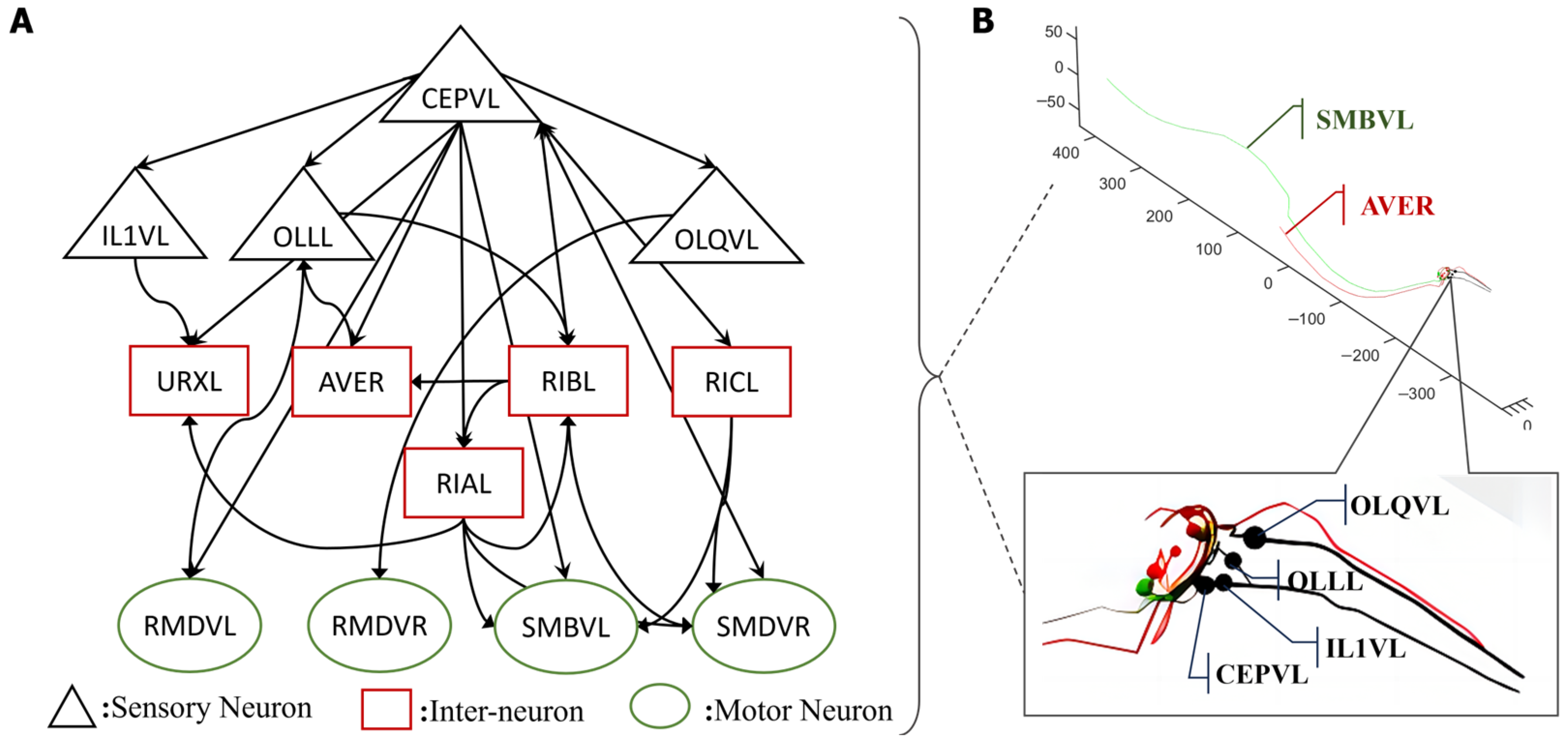
2.1.3. Control Circuit Identification
2.2. Robotic Platforms
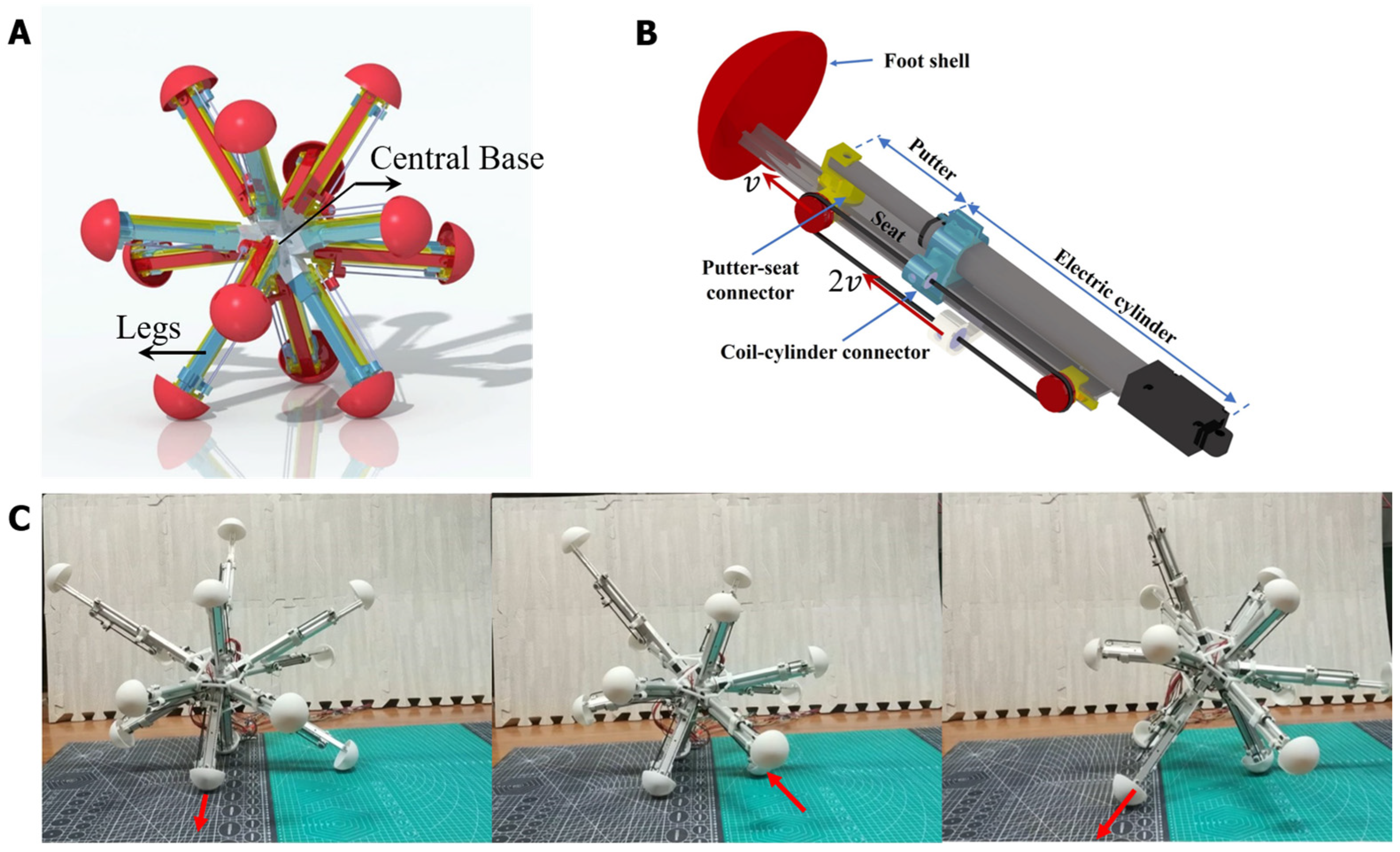
2.2.1. Twelve-Legged Radial-Skeleton Robot
2.2.2. Kinetic Model of the Robot for Simulation
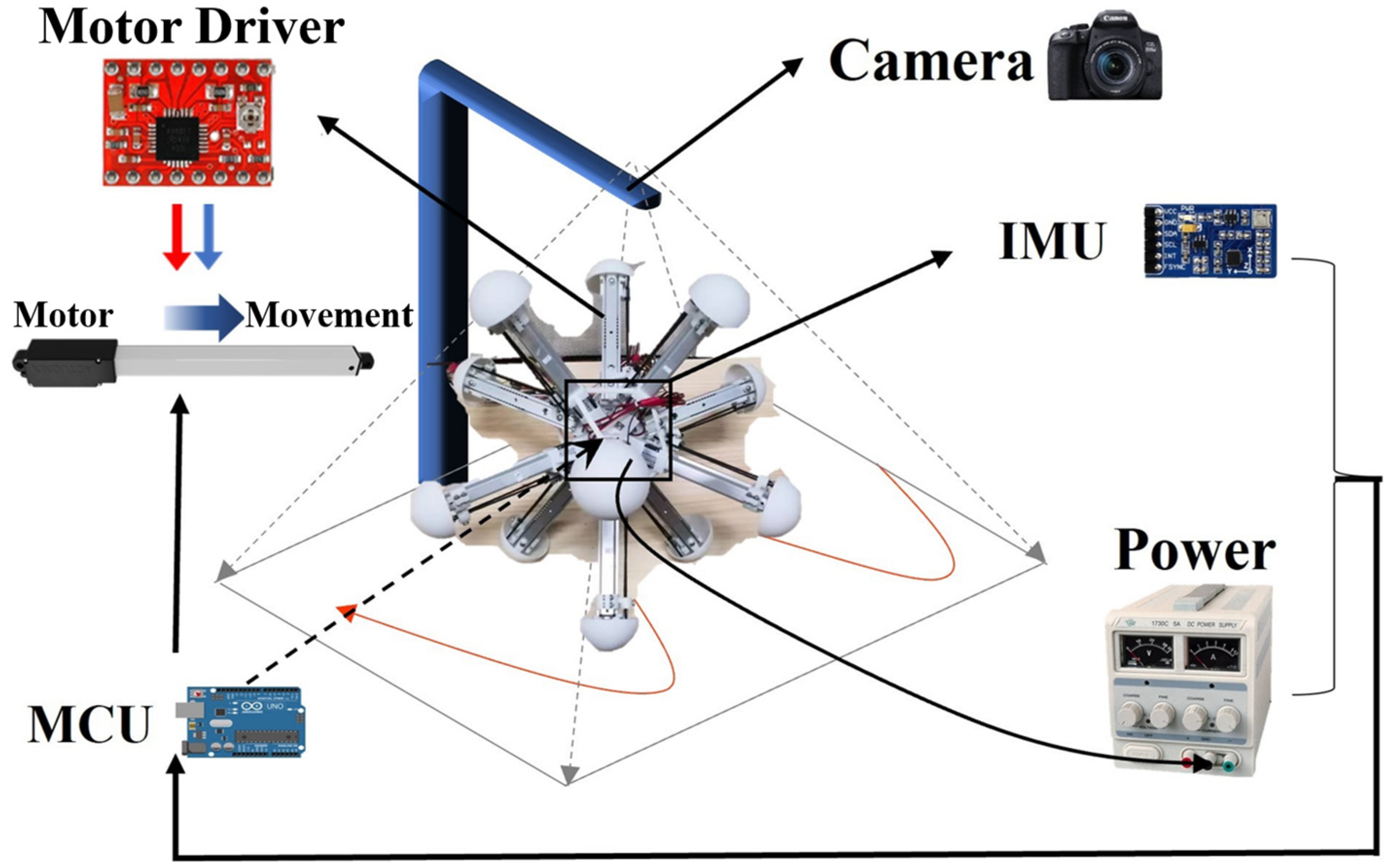
2.2.3. Construction of the Experimental Platform
3. Results
3.1. Visualization of the Whole-Brain BNN Model
3.2. The BNN Model Controls Robot Orientation
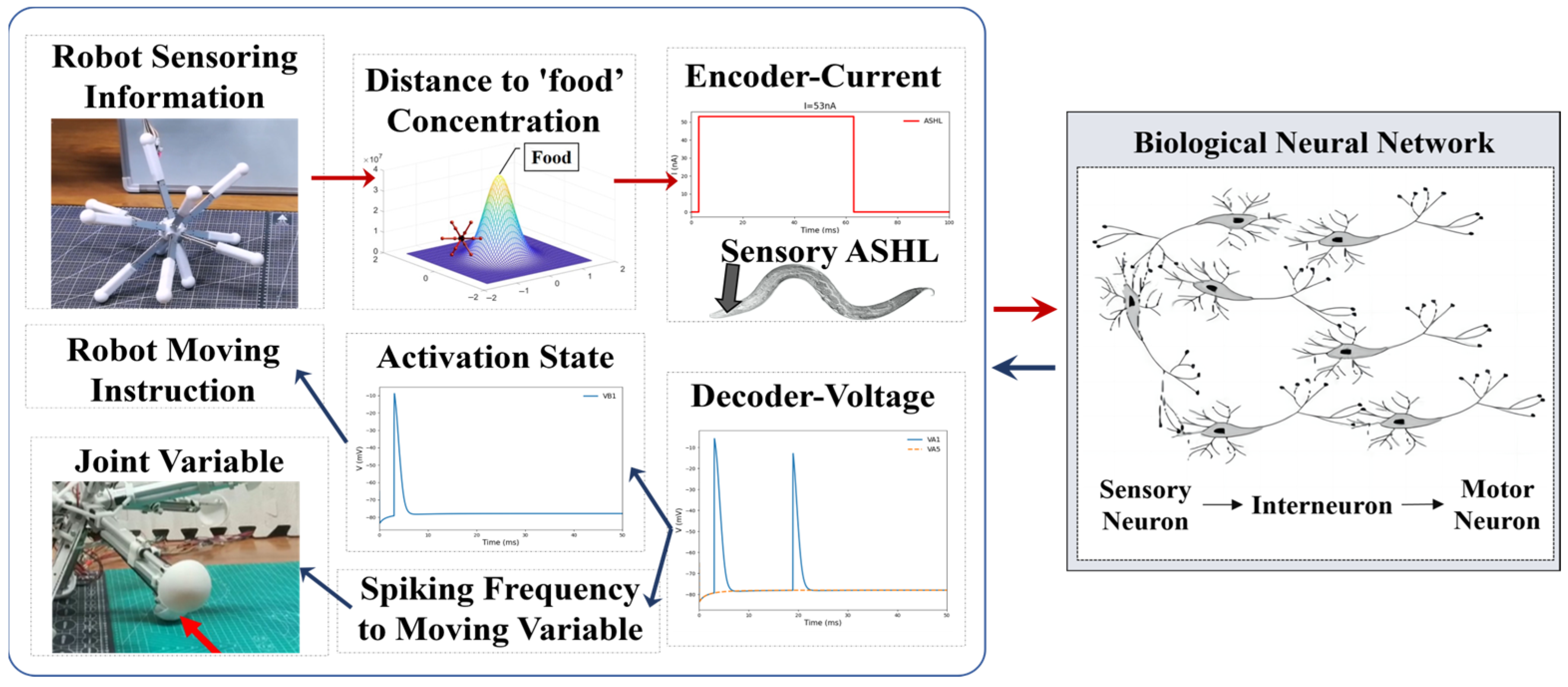
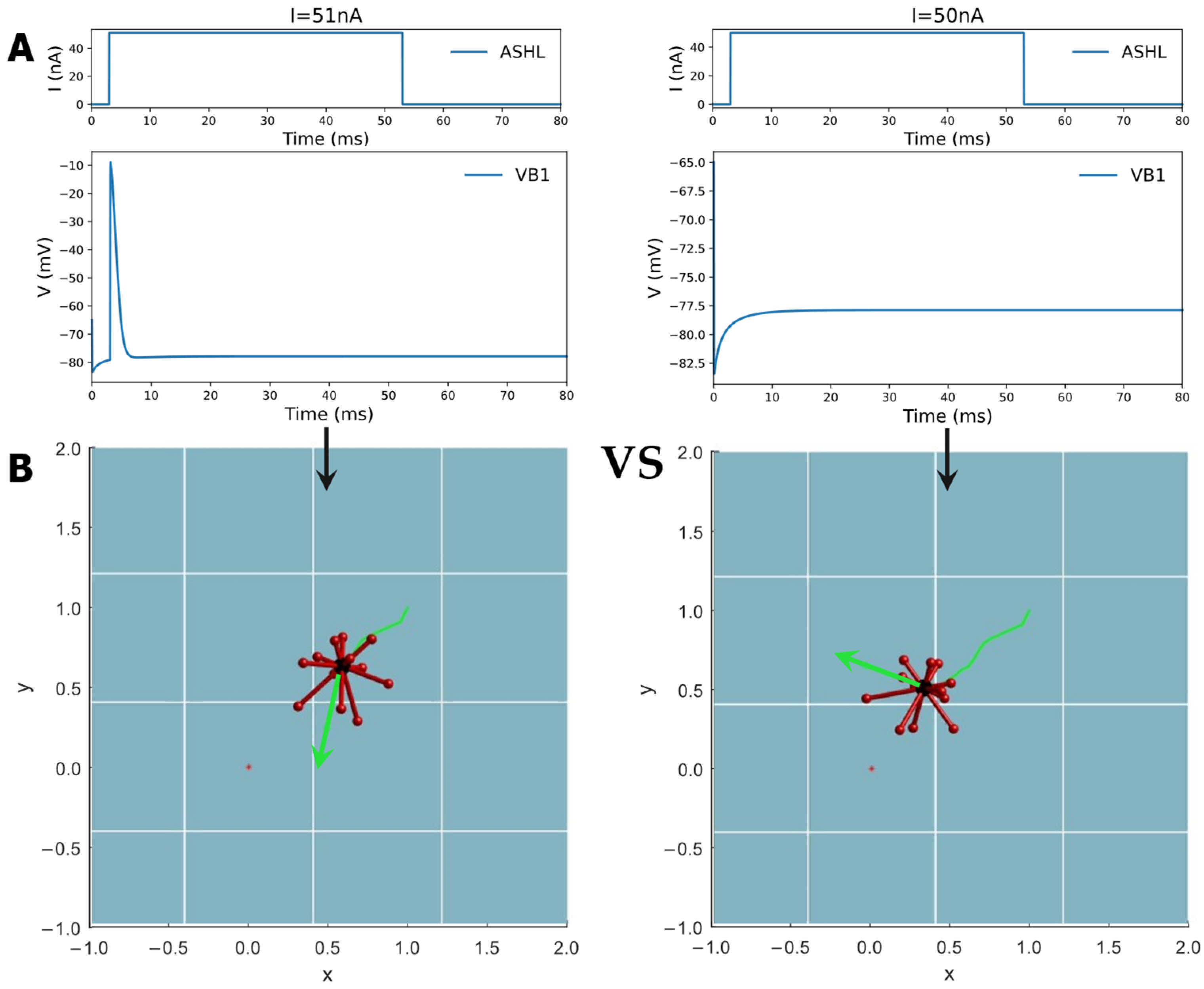
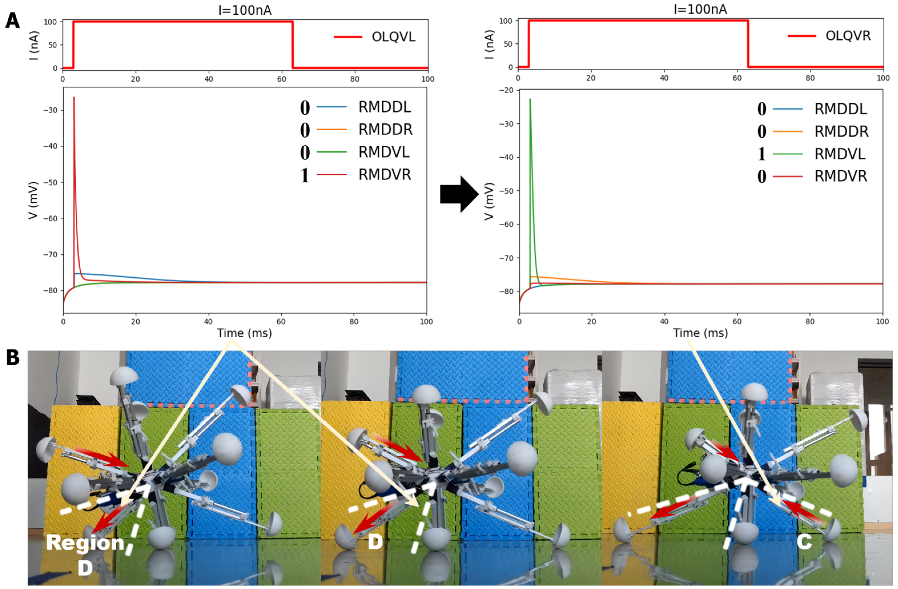
3.2.1. Mechanism by Which BNN Controls the Robot
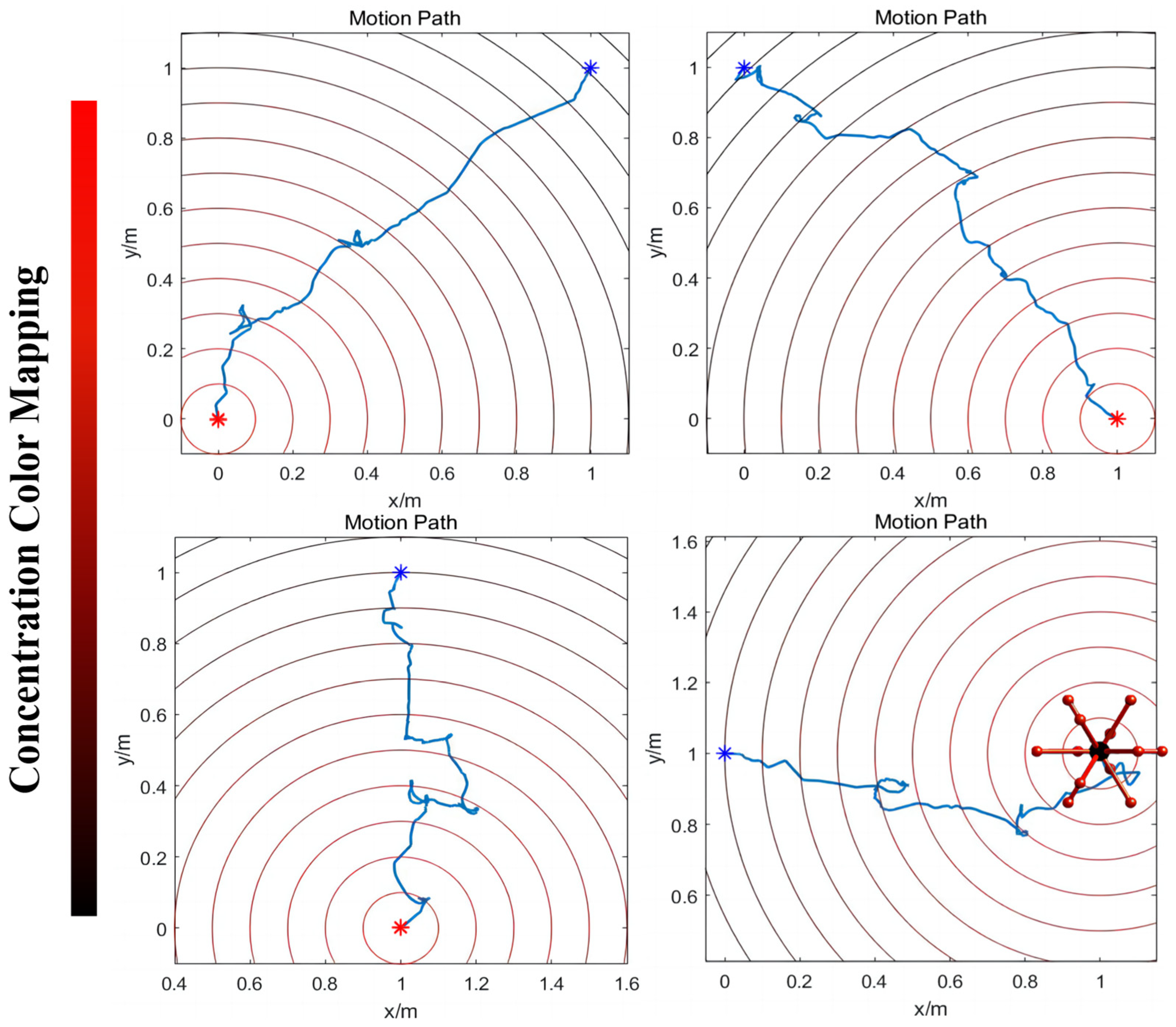
3.2.2. Innate ‘Foraging’ Behavior Control
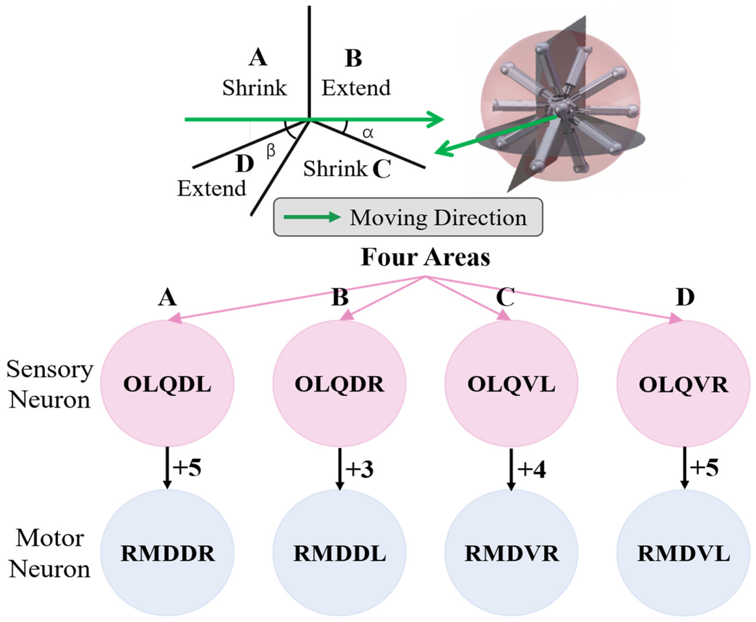
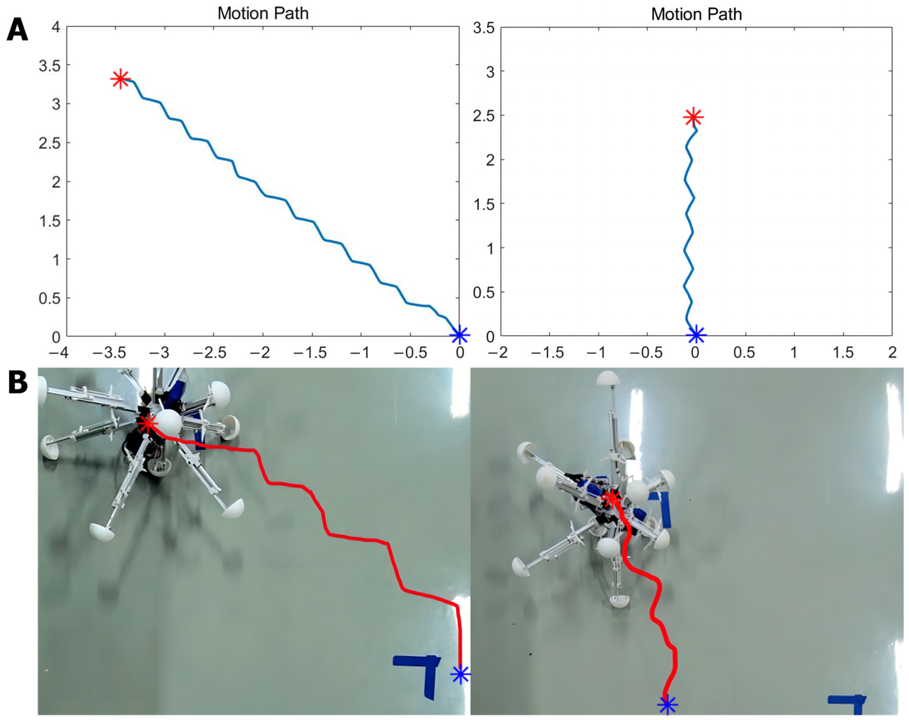
3.2.3. Omnidirectional Locomotion Control
3.3. Experimental Validation of the BNN Control
4. Discussion
4.1. Contributions and Limitations
4.2. Analysis of Results
Supplementary Materials
Author Contributions
Funding
Institutional Review Board Statement
Data Availability Statement
Conflicts of Interest
References
- Dorkenwald, S.; Matsliah, A.; Sterling, A.R.; Schlegel, P.; Yu, S.-C.; McKellar, C.E.; Lin, A.; Costa, M.; Eichler, K.; Yin, Y. Neuronal wiring diagram of an adult brain. bioRxiv 2023. [Google Scholar] [CrossRef]
- Deco, G.; Tononi, G.; Boly, M.; Kringelbach, M.L. Rethinking segregation and integration: Contributions of whole-brain modelling. Nat. Rev. Neurosci. 2015, 16, 430–439. [Google Scholar] [CrossRef]
- Cakan, C.; Jajcay, N.; Obermayer, K. Neurolib: A simulation framework for whole-brain neural mass modeling. Cogn. Comput. 2023, 15, 1132–1152. [Google Scholar] [CrossRef]
- Blachowicz, T.; Grzybowski, J.; Steblinski, P.; Ehrmann, A. Neuro-inspired signal processing in ferromagnetic nanofibers. Biomimetics 2021, 6, 32. [Google Scholar] [CrossRef]
- Mujika, A.; Leškovský, P.; Álvarez, R.; Otaduy, M.A.; Epelde, G. Modeling behavioral experiment interaction and environmental stimuli for a synthetic C. elegans. Front. Neuroinform. 2017, 11, 71. [Google Scholar] [CrossRef] [PubMed]
- Lechner, M.; Hasani, R.; Amini, A.; Henzinger, T.A.; Rus, D.; Grosu, R. Neural circuit policies enabling auditable autonomy. Nat. Mach. Intell. 2020, 2, 642–652. [Google Scholar] [CrossRef]
- Sarma, G.P.; Lee, C.W.; Portegys, T.; Ghayoomie, V.; Jacobs, T.; Alicea, B.; Cantarelli, M.; Currie, M.; Gerkin, R.C.; Gingell, S. OpenWorm: Overview and recent advances in integrative biological simulation of Caenorhabditis elegans. Philos. Trans. R. Soc. B 2018, 373, 20170382. [Google Scholar] [CrossRef] [PubMed]
- Black, L. A Worm’s Mind in a Lego Body. Available online: https://www.i-programmer.info/news/105-artificial-intelli-%20920%20gence/7985-a-worms-mind-in-a-lego-body.html (accessed on 16 November 2014).
- Gingell, S.; Portegys, T. A Food Foraging C. elegans Robot. May 2019. Available online: https://www.researchgate.net/publication/333506681_A_food_foraging_C_elegans_robot (accessed on 16 November 2014).
- Deng, X.; Xu, J.-X.; Wang, J.; Wang, G.-y.; Chen, Q.-s. Biological modeling the undulatory locomotion of C. elegans using dynamic neural network approach. Neurocomputing 2016, 186, 207–217. [Google Scholar] [CrossRef]
- Yin, X.; Noguchi, N.; Choi, J. Development of a target recognition and following system for a field robot. Comput. Electron. Agric. 2013, 98, 17–24. [Google Scholar] [CrossRef]
- Tsalik, E.L.; Hobert, O. Functional mapping of neurons that control locomotory behavior in Caenorhabditis elegans. J. Neurobiol. 2003, 56, 178–197. [Google Scholar] [CrossRef]
- Schafer, W.R. Mechanosensory molecules and circuits in C. elegans. Pflüg. Arch. Eur. J. Physiol. 2015, 467, 39–48. [Google Scholar] [CrossRef] [PubMed]
- Zhen, M.; Samuel, A.D. C. elegans locomotion: Small circuits, complex functions. Curr. Opin. Neurobiol. 2015, 33, 117–126. [Google Scholar] [CrossRef] [PubMed]
- Gray, J.M.; Hill, J.J.; Bargmann, C.I. A circuit for navigation in Caenorhabditis elegans. Proc. Natl. Acad. Sci. USA 2005, 102, 3184–3191. [Google Scholar] [CrossRef]
- Riddle, D.L.; Blumenthal, T.; Meyer, B.J.; Priess, J.R. C. elegans II; Cold Spring Harbor Laboratory Press: Cold Spring Harbor, NY, USA, 1997. [Google Scholar]
- Yang, D.; Yang, S.; Yu, Y.; Wang, Q. Design and Experiment of Complex Terrain Adaptive Robot Based on Deep Reinforcement Learning. J. Astronaut. 2022, 43, 1176. [Google Scholar] [CrossRef]
- Venkataraman, A.; Jagadeesha, K.K. Evaluation of inter-process communication mechanisms. Architecture 2015, 86, 64. [Google Scholar]
- Izquierdo, E.J.; Beer, R.D. Connecting a connectome to behavior: An ensemble of neuroanatomical models of C. elegans klinotaxis. PLoS Comput. Biol. 2013, 9, e1002890. [Google Scholar] [CrossRef] [PubMed]
- Mohammadi, A.; Byrne Rodgers, J.; Kotera, I.; Ryu, W.S. Behavioral response of Caenorhabditis elegans to localized thermal stimuli. BMC Neurosci. 2013, 14, 66. [Google Scholar] [CrossRef] [PubMed]
- Milward, K.; Busch, K.E.; Murphy, R.J.; De Bono, M.; Olofsson, B. Neuronal and molecular substrates for optimal foraging in Caenorhabditis elegans. Proc. Natl. Acad. Sci. USA 2011, 108, 20672–20677. [Google Scholar] [CrossRef]
- Goodman, M.B.; Sengupta, P. How Caenorhabditis elegans senses mechanical stress, temperature, and other physical stimuli. Genetics 2019, 212, 25–51. [Google Scholar] [CrossRef]
- Chatzigeorgiou, M.; Bang, S.; Hwang, S.W.; Schafer, W.R. tmc-1 encodes a sodium-sensitive channel required for salt chemosensation in C. elegans. Nature 2013, 494, 95–99. [Google Scholar] [CrossRef]
- Altun, Z.F.; Herndon, L.A.; Wolkow, C.A.; Crocker, C.; Lints, R.; Hall, D.H. WormAtlas; 2002–2024. Available online: http://www.wormatlas.org (accessed on 24 March 2024).
- Kaplan, J.M.; HoRVITZ, H.R. A dual mechanosensory and chemosensory neuron in Caenorhabditis elegans. Proc. Natl. Acad. Sci. USA 1993, 90, 2227–2231. [Google Scholar] [CrossRef] [PubMed]
- Sawin, E.R.; Ranganathan, R.; Horvitz, H.R. C. elegans locomotory rate is modulated by the environment through a dopaminergic pathway and by experience through a serotonergic pathway. Neuron 2000, 26, 619–631. [Google Scholar] [CrossRef]
- McDonald, P.W.; Hardie, S.L.; Jessen, T.N.; Carvelli, L.; Matthies, D.S.; Blakely, R.D. Vigorous motor activity in Caenorhabditis elegans requires efficient clearance of dopamine mediated by synaptic localization of the dopamine transporter DAT-1. J. Neurosci. 2007, 27, 14216–14227. [Google Scholar] [CrossRef] [PubMed]
- Wen, Q.; Po, M.D.; Hulme, E.; Chen, S.; Liu, X.; Kwok, S.W.; Gershow, M.; Leifer, A.M.; Butler, V.; Fang-Yen, C. Proprioceptive coupling within motor neurons drives C. elegans forward locomotion. Neuron 2012, 76, 750–761. [Google Scholar] [CrossRef] [PubMed]
- Faumont, S.; Lindsay, T.; Lockery, S. Neuronal microcircuits for decision making in C. elegans. Curr. Opin. Neurobiol. 2012, 22, 580–591. [Google Scholar] [CrossRef] [PubMed]
- Fenyves, B.G.; Szilágyi, G.S.; Vassy, Z.; Sőti, C.; Csermely, P. Synaptic polarity and sign-balance prediction using gene expression data in the Caenorhabditis elegans chemical synapse neuronal connectome network. PLoS Comput. Biol. 2020, 16, e1007974. [Google Scholar] [CrossRef] [PubMed]
- Hodgkin, A.L.; Huxley, A.F. A quantitative description of membrane current and its application to conduction and excitation in nerve. J. Physiol. 1952, 117, 500. [Google Scholar] [CrossRef]
- Nicoletti, M.; Loppini, A.; Chiodo, L.; Folli, V.; Ruocco, G.; Filippi, S. Biophysical modeling of C. elegans neurons: Single ion currents and whole-cell dynamics of AWCon and RMD. PLoS ONE 2019, 14, e0218738. [Google Scholar] [CrossRef]
- Kang, L.; Gao, J.; Schafer, W.R.; Xie, Z.; Xu, X.S. C. elegans TRP family protein TRP-4 is a pore-forming subunit of a native mechanotransduction channel. Neuron 2010, 67, 381–391. [Google Scholar] [CrossRef]
- Davis, P.; Zarowiecki, M.; Arnaboldi, V.; Becerra, A.; Cain, S.; Chan, J.; Chen, W.J.; Cho, J.; da Veiga Beltrame, E.; Diamantakis, S. WormBase in 2022—Data, processes, and tools for analyzing Caenorhabditis elegans. Genetics 2022, 220, iyac003. [Google Scholar] [CrossRef]
- Wang, J.; Chen, L.; Fei, X. Analysis and control of the bifurcation of Hodgkin–Huxley model. Chaos Solitons Fractals 2007, 31, 247–256. [Google Scholar] [CrossRef]
- Nielsen, M.S.; Axelsen, L.N.; Sorgen, P.L.; Verma, V.; Delmar, M.; Holstein-Rathlou, N.-H. Gap junctions. Compr. Physiol. 2012, 2, 1981–2035. [Google Scholar] [CrossRef] [PubMed]
- Hall, D.H. Gap junctions in C. elegans: Their roles in behavior and development. Dev. Neurobiol. 2017, 77, 587–596. [Google Scholar] [CrossRef] [PubMed]
- Vogel, R.; Weingart, R. Mathematical model of vertebrate gap junctions derived from electrical measurements on homotypic and heterotypic channels. J. Physiol. 1998, 510 Pt 1, 177. [Google Scholar] [CrossRef]
- Awile, O.; Kumbhar, P.; Cornu, N.; Dura-Bernal, S.; King, J.G.; Lupton, O.; Magkanaris, I.; McDougal, R.A.; Newton, A.J.; Pereira, F. Modernizing the NEURON simulator for sustainability, portability, and performance. Front. Neuroinform. 2022, 16, 884046. [Google Scholar] [CrossRef] [PubMed]
- Kindt, K.S.; Viswanath, V.; Macpherson, L.; Quast, K.; Hu, H.; Patapoutian, A.; Schafer, W.R. Caenorhabditis elegans TRPA-1 functions in mechanosensation. Nat. Neurosci. 2007, 10, 568–577. [Google Scholar] [CrossRef] [PubMed]
- Zhang, F.; Yu, Y.; Wang, Q.; Zeng, X.; Niu, H. A terrain-adaptive robot prototype designed for bumpy-surface exploration. Mech. Mach. Theory 2019, 141, 213–225. [Google Scholar] [CrossRef]
- Zhang, F.; Yu, Y.; Wang, Q.; Zeng, X. Physics-driven locomotion planning method for a planar closed-loop terrain-adaptive robot. Mech. Mach. Theory 2021, 162, 104353. [Google Scholar] [CrossRef]
- Yang, D.; Liu, Y.; Ding, F.; Yu, Y. Bionic Multi-legged Robot Based on End-to-end Artificial Neural Network Control. In Proceedings of the 2022 IEEE International Conference on Cyborg and Bionic Systems (CBS), Wuhan, China, 24–26 March 2023; pp. 104–109. [Google Scholar]
- Yang, D.; Liu, Y.; Yu, Y. A General Locomotion Approach for a Novel Multi-legged Spherical Robot. In Proceedings of the 2023 IEEE International Conference on Robotics and Automation (ICRA), London, UK, 29 May–2 June 2023; pp. 10146–10152. [Google Scholar]
- Xue, M.; Zhu, C. The socket programming and software design for communication based on client/server. In Proceedings of the 2009 Pacific-Asia Conference on Circuits, Communications and Systems, Chengdu, China, 16–17 May 2009; pp. 775–777. [Google Scholar]
- Akram, M.A.; Nanda, S.; Maraver, P.; Armañanzas, R.; Ascoli, G.A. An open repository for single-cell reconstructions of the brain forest. Sci. Data 2018, 5, 1–12. [Google Scholar]
- Towlson, E.K.; Vértes, P.E.; Yan, G.; Chew, Y.L.; Walker, D.S.; Schafer, W.R.; Barabási, A.-L. Caenorhabditis elegans and the network control framework—FAQs. Philos. Trans. R. Soc. B Biol. Sci. 2018, 373, 20170372. [Google Scholar] [CrossRef]
- Brezina, V.; Orekhova, I.V.; Weiss, K.R. The neuromuscular transform: The dynamic, nonlinear link between motor neuron firing patterns and muscle contraction in rhythmic behaviors. J. Neurophysiol. 2000, 83, 207–231. [Google Scholar] [CrossRef] [PubMed]
- Hills, T.; Brockie, P.J.; Maricq, A.V. Dopamine and glutamate control area-restricted search behavior in Caenorhabditis elegans. J. Neurosci. 2004, 24, 1217–1225. [Google Scholar] [CrossRef] [PubMed]
- Pradhan, S.; Quilez, S.; Homer, K.; Hendricks, M. Environmental programming of adult foraging behavior in C. elegans. Curr. Biol. 2019, 29, 2867–2879.e4. [Google Scholar] [CrossRef] [PubMed]
- Petzold, B.C.; Park, S.-J.; Ponce, P.; Roozeboom, C.; Powell, C.; Goodman, M.B.; Pruitt, B.L. Caenorhabditis elegans body mechanics are regulated by body wall muscle tone. Biophys. J. 2011, 100, 1977–1985. [Google Scholar] [CrossRef] [PubMed]
- Wei, H.; Ye, J.; Li, J.; Wang, Y. Design and Simulation of a Hierarchical Parallel Distributed Processing Model for Orientation Selection Based on Primary Visual Cortex. Biomimetics 2023, 8, 314. [Google Scholar] [CrossRef]
- Zeng, T.; Si, B. A brain-inspired compact cognitive mapping system. Cogn. Neurodyn. 2021, 15, 91–101. [Google Scholar] [CrossRef]
- Baxter, D.A.; Byrne, J.H. Learning rules from neurobiology. In Neurobiology of Neural Networks; The MIT Press: Cambridge, MA, USA, 1993. [Google Scholar] [CrossRef]


| Parameters | Values |
|---|---|
| 3.1 | |
| 0.289 nS | |
| 75 mV | |
| 55 mV | |
| 84 mV | |
| 45 mV |
| Sensory Neuron (Mechanosensory) | Motor Neuron | Current Stimuli Value Range (Unit: nA) |
|---|---|---|
| ASHL | DA, DB, VA, VB, VD, SMB, SMD, RMB, RMD | 60- (One action potential only) |
| ADEL | DA, DB, VA, VB, VD | 59–64 (Oscillation Range) |
| ADER | DA, DB, VA, VB, VD | 59–68 (Oscillation Range) |
| CEPDL | DA, DB, VA, VB, VD, SMB, SMD, RMB, RMD | 64–111 (Oscillation Range) |
| CEPDR | DA, DB, VA, VB, VD, SMB, SMD, RMB, RMD | 64–91 (Oscillation Range) |
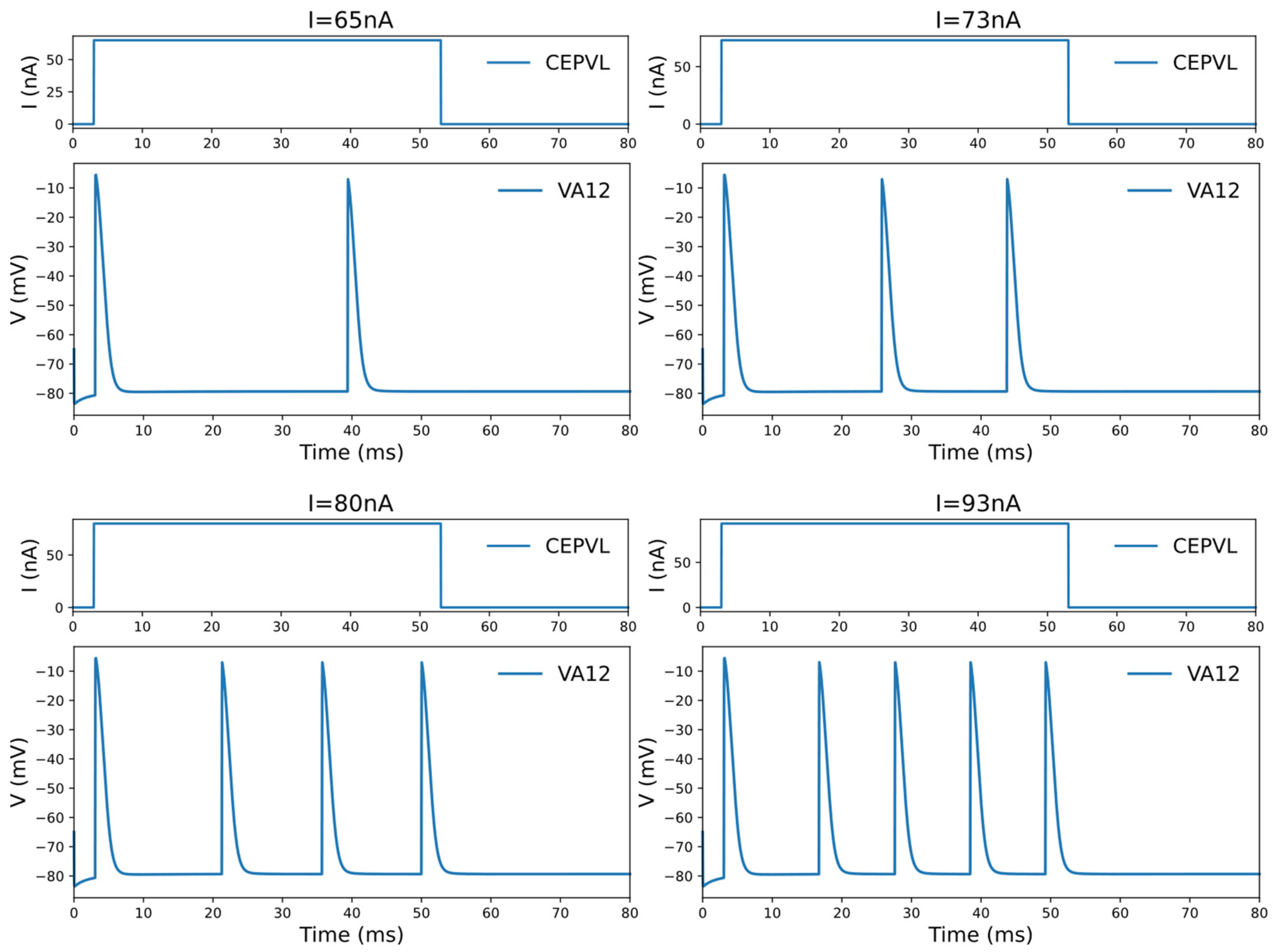
| CEPVL | DA, DB, VA, VB, VD, SMB, SMD, RMB, RMD | 64–111 (Oscillation Range) |
| CEPVR | DA, DB, VA, VB, VD, SMB, SMD, RMB, RMD | 64–85 (Oscillation Range) |
| PDEL | DA, DB, VA, VB, SMDVL | 60–190 (Oscillation Range) |
| PDER | DA, DB, VA, VB, VD, SMB, SMD, RMB, RMD | 60–88 (Oscillation Range) |
| OLQDL | RMDDR | 91– (One action potential only) |
| OLQDR | RMDDL | 91– (One action potential only) |
| OLQVL | RMDVR | 91– (One action potential only) |
| OLQVR | RMDVL | 94– (One action potential only) |
Disclaimer/Publisher’s Note: The statements, opinions and data contained in all publications are solely those of the individual author(s) and contributor(s) and not of MDPI and/or the editor(s). MDPI and/or the editor(s) disclaim responsibility for any injury to people or property resulting from any ideas, methods, instructions or products referred to in the content. |
© 2024 by the authors. Licensee MDPI, Basel, Switzerland. This article is an open access article distributed under the terms and conditions of the Creative Commons Attribution (CC BY) license (https://creativecommons.org/licenses/by/4.0/).
Share and Cite
Hu, K.; Zhang, Y.; Ding, F.; Yang, D.; Yu, Y.; Yu, Y.; Wang, Q.; Baoyin, H. Innate Orientating Behavior of a Multi-Legged Robot Driven by the Neural Circuits of C. elegans. Biomimetics 2024, 9, 314. https://doi.org/10.3390/biomimetics9060314
Hu K, Zhang Y, Ding F, Yang D, Yu Y, Yu Y, Wang Q, Baoyin H. Innate Orientating Behavior of a Multi-Legged Robot Driven by the Neural Circuits of C. elegans. Biomimetics. 2024; 9(6):314. https://doi.org/10.3390/biomimetics9060314
Chicago/Turabian StyleHu, Kangxin, Yu Zhang, Fei Ding, Dun Yang, Yang Yu, Ying Yu, Qingyun Wang, and Hexi Baoyin. 2024. "Innate Orientating Behavior of a Multi-Legged Robot Driven by the Neural Circuits of C. elegans" Biomimetics 9, no. 6: 314. https://doi.org/10.3390/biomimetics9060314
APA StyleHu, K., Zhang, Y., Ding, F., Yang, D., Yu, Y., Yu, Y., Wang, Q., & Baoyin, H. (2024). Innate Orientating Behavior of a Multi-Legged Robot Driven by the Neural Circuits of C. elegans. Biomimetics, 9(6), 314. https://doi.org/10.3390/biomimetics9060314