
Dynamic Analysis of the Locomotion Mechanism in Foxtail Robots: Frictional Anisotropy and Bristle Diversity


Abstract

1. Introduction
2. Methodology
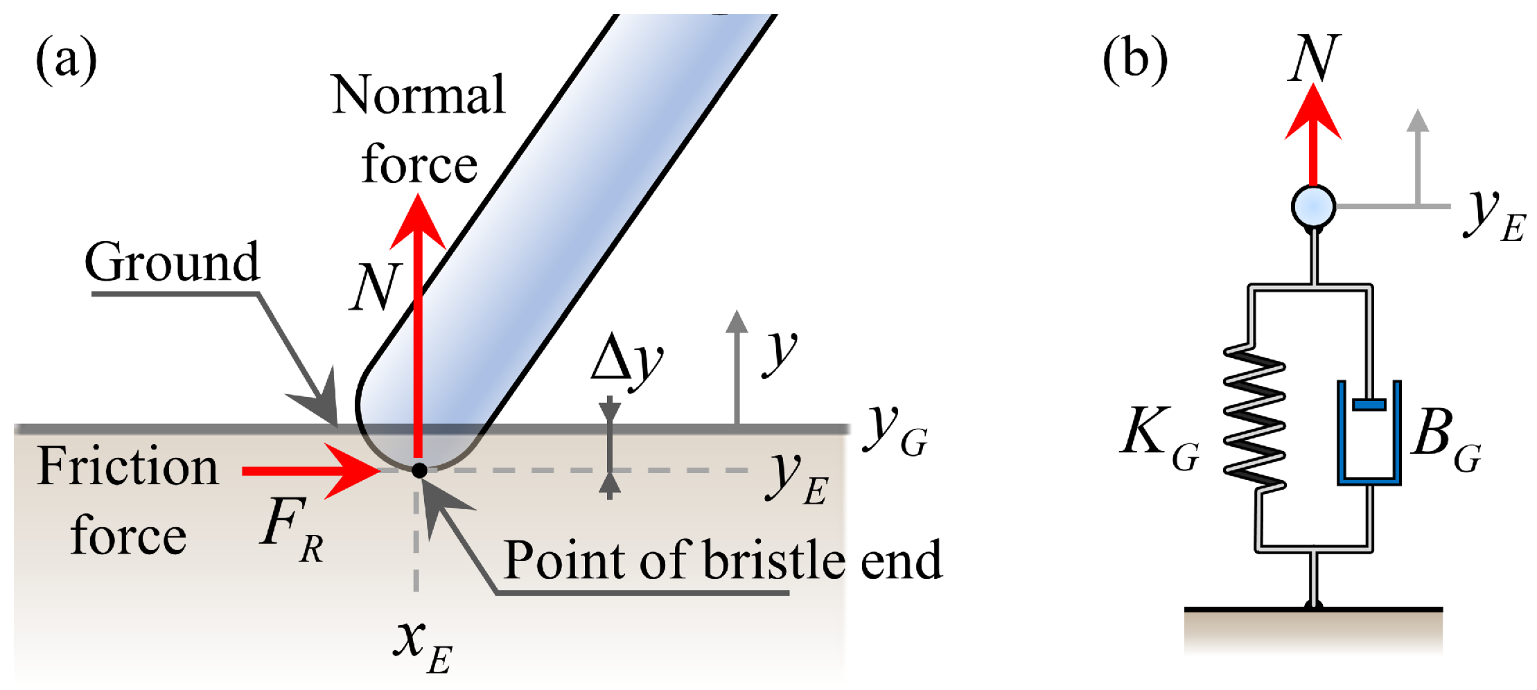
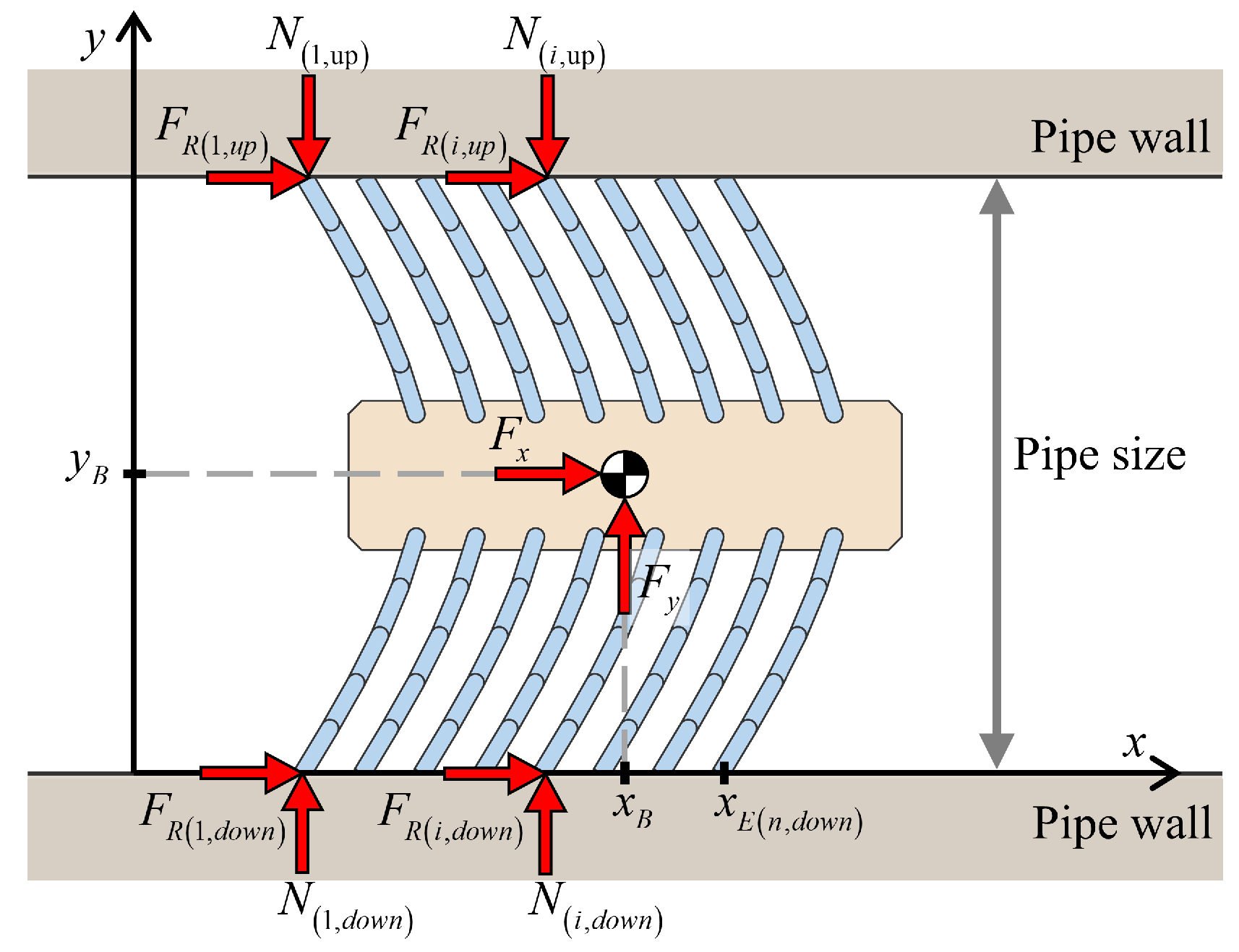
2.1. Ground Contact Model
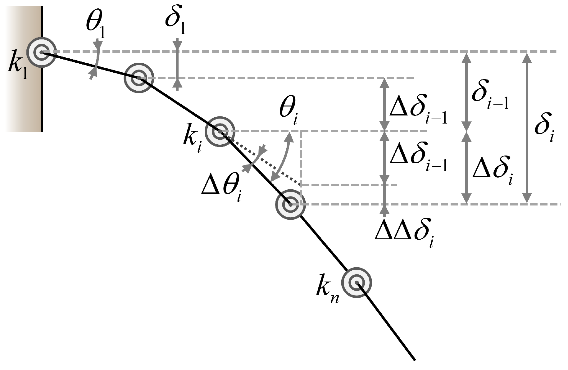
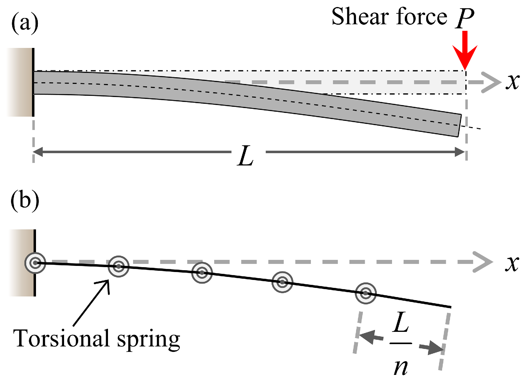
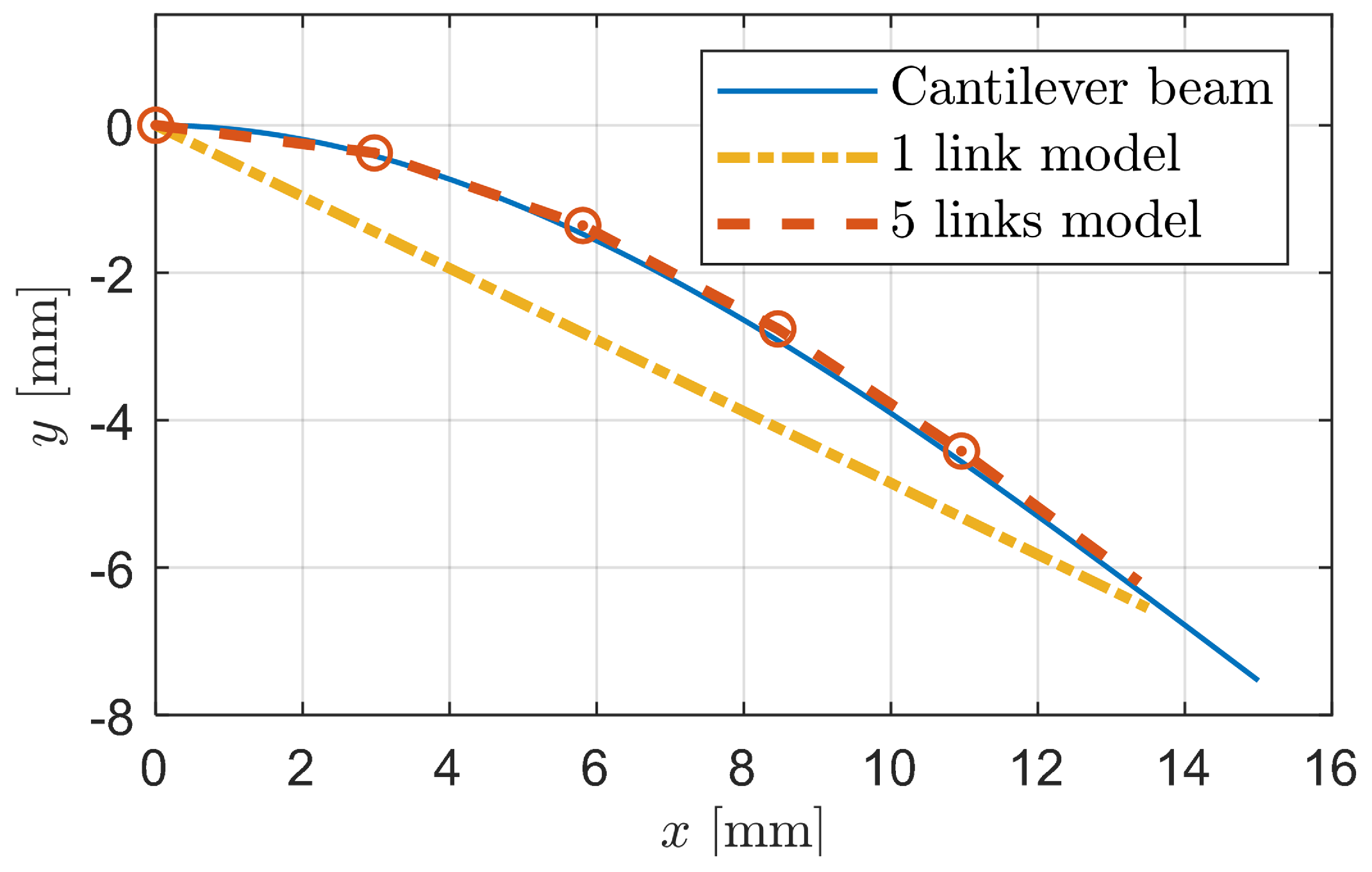
2.2. Linkage-Spring Model
2.3. Dynamic Analysis Using Euler–Lagrange Method
2.4. Specification
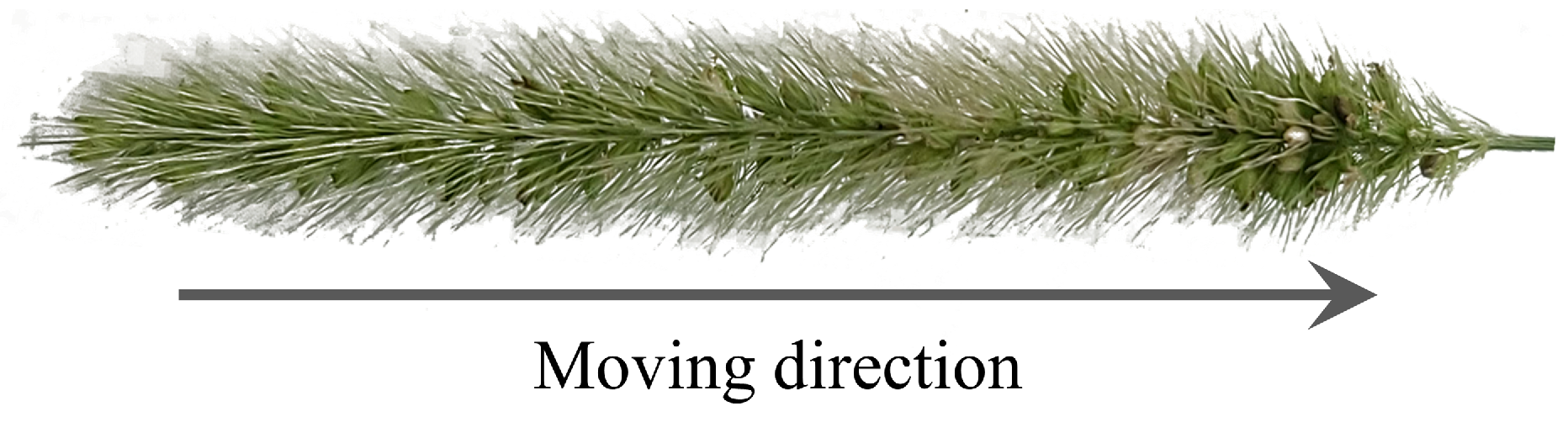
3. Bristle Model
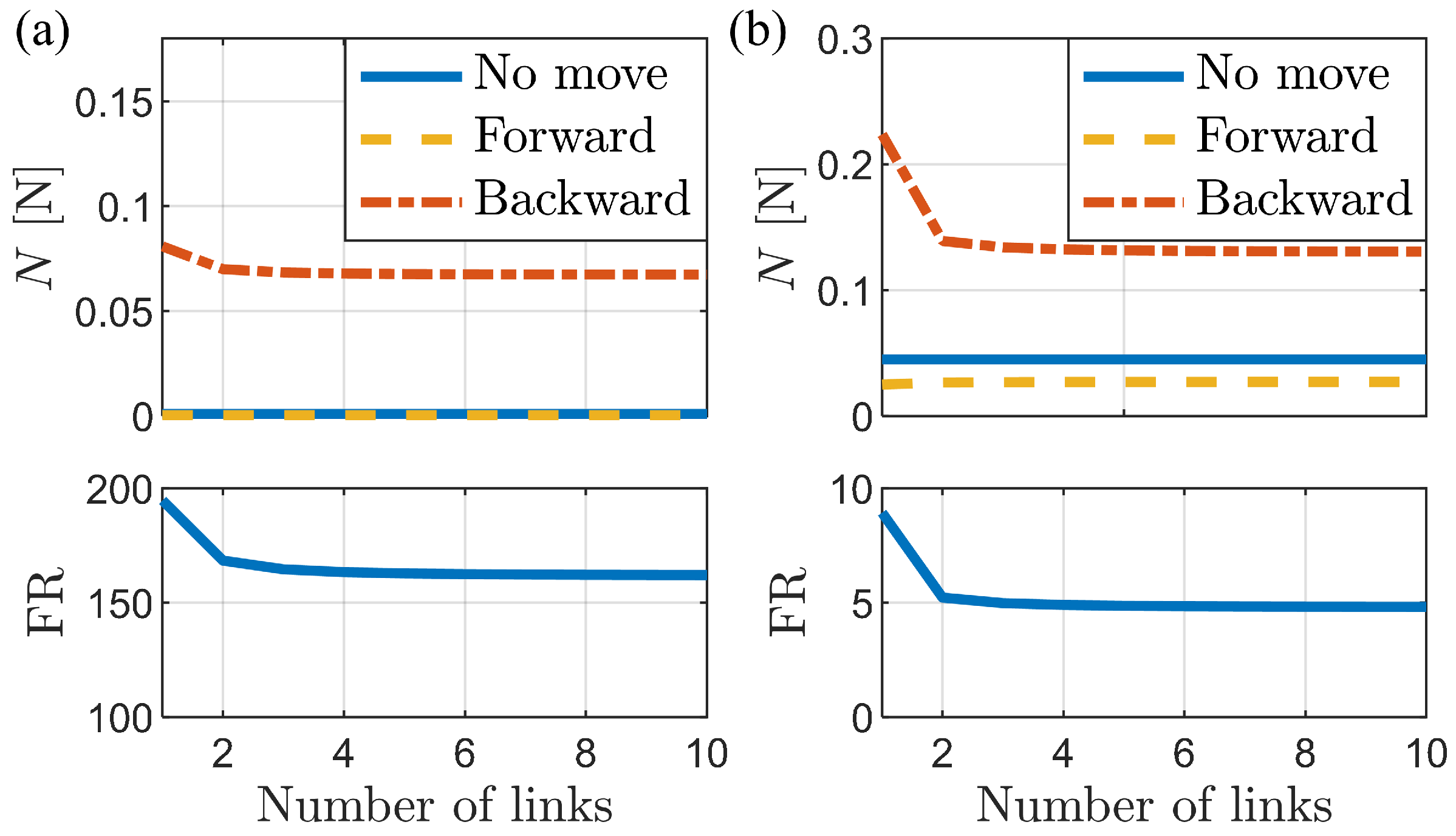
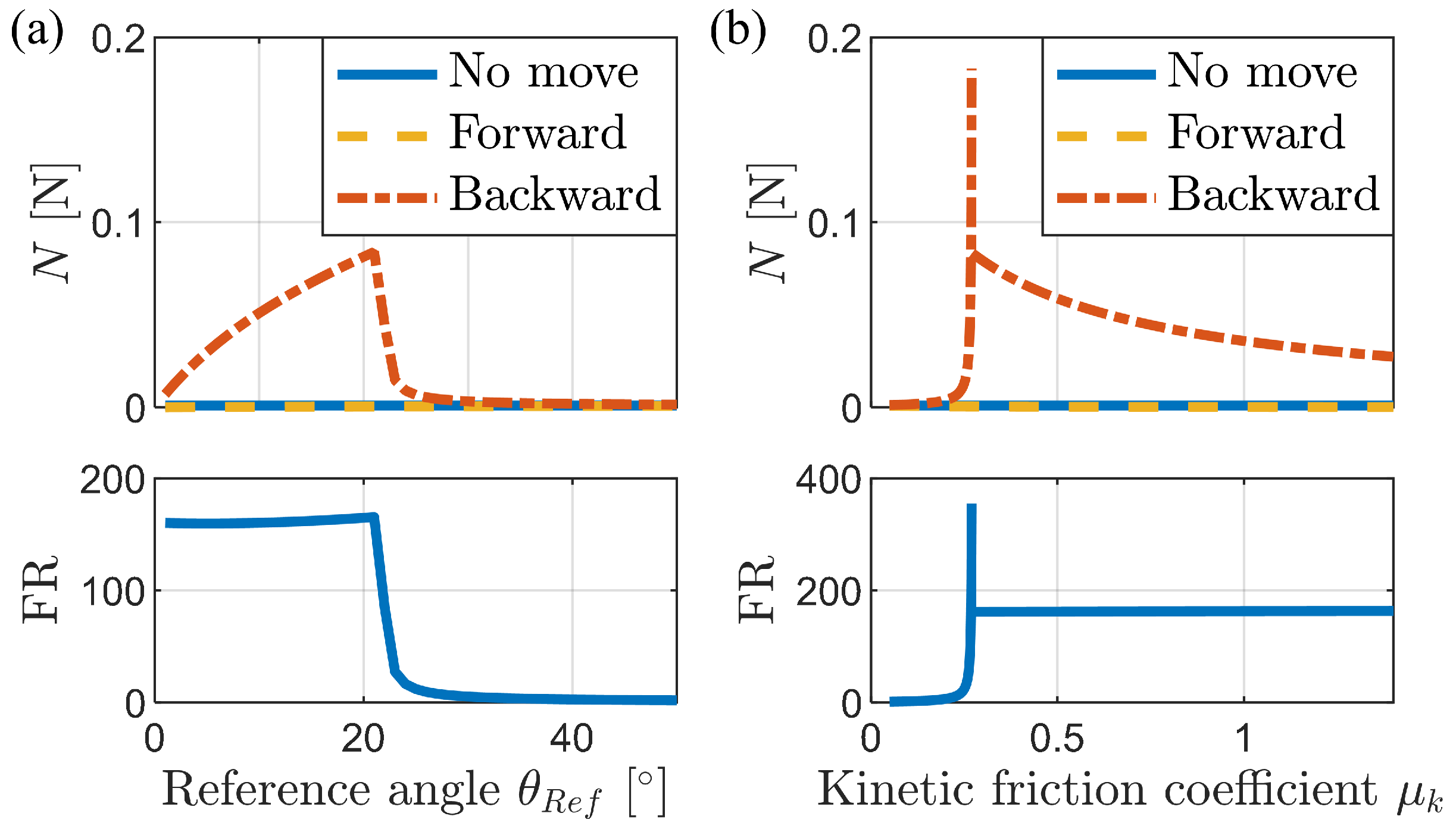
3.1. Analysis of Frictional Anisotropy Based on Changes in Major Design Parameters
3.2. Simulation of the Bristle Model
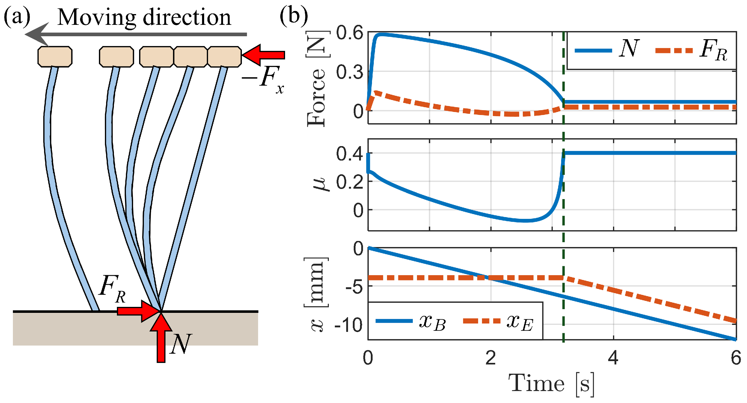
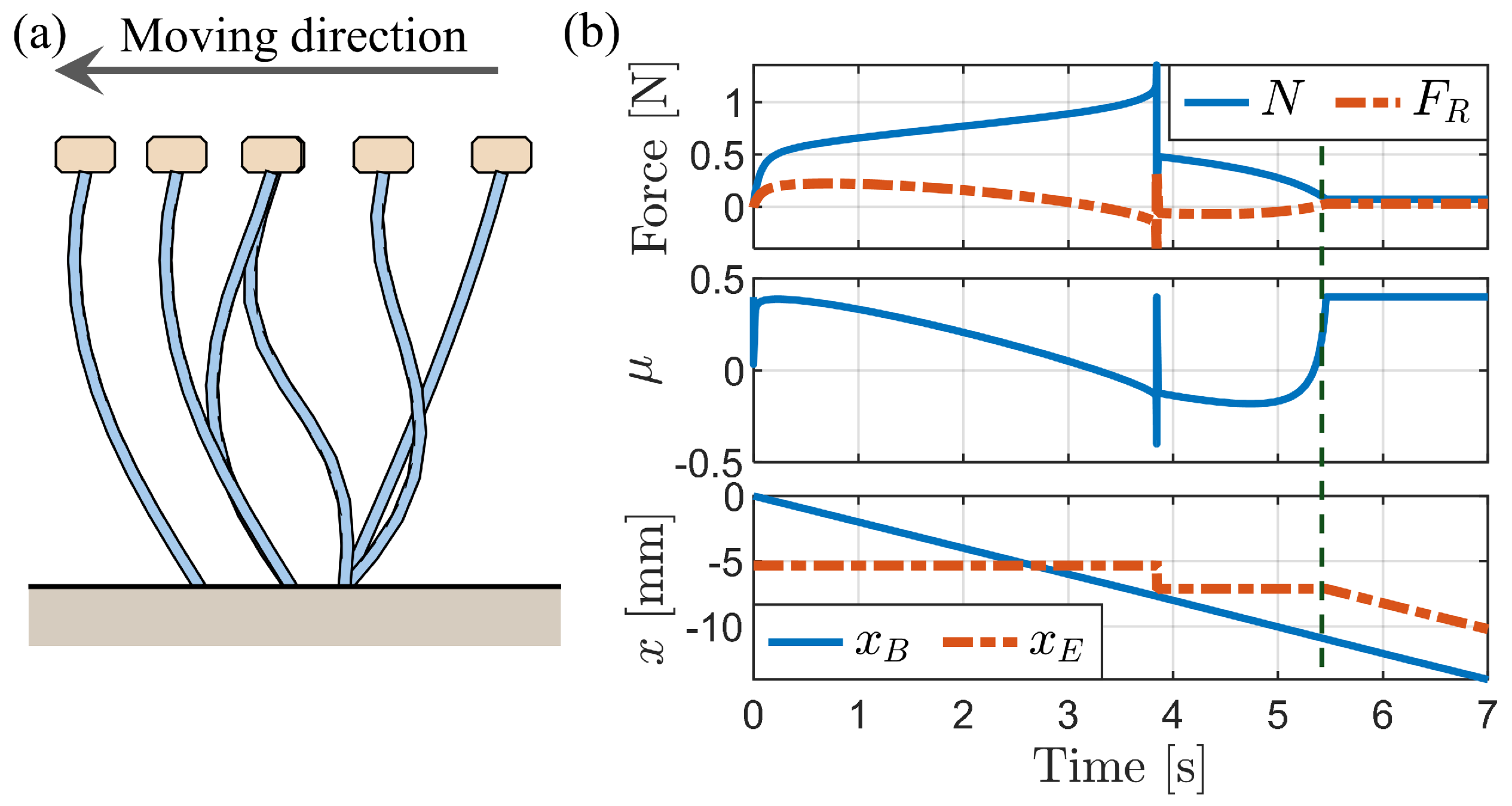
3.2.1. Simulation of Buckling Behavior during Backward Motion
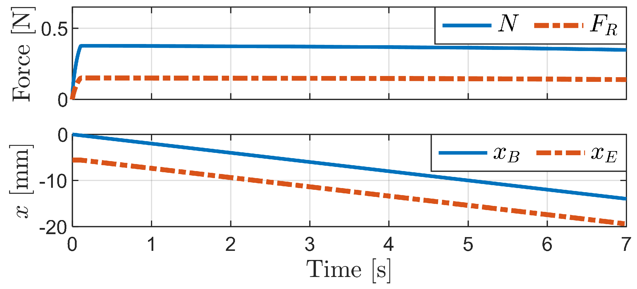
3.2.2. Press-and-Release Simulation
4. Foxtail Robot Model
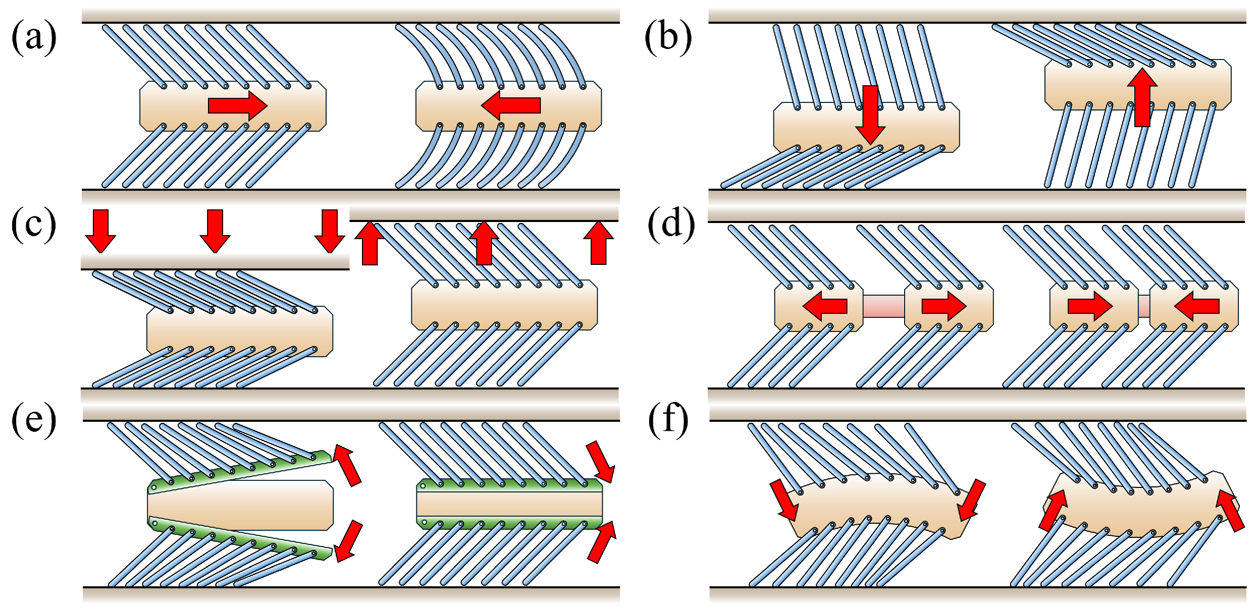
4.1. Passive Locomotion by External Forces
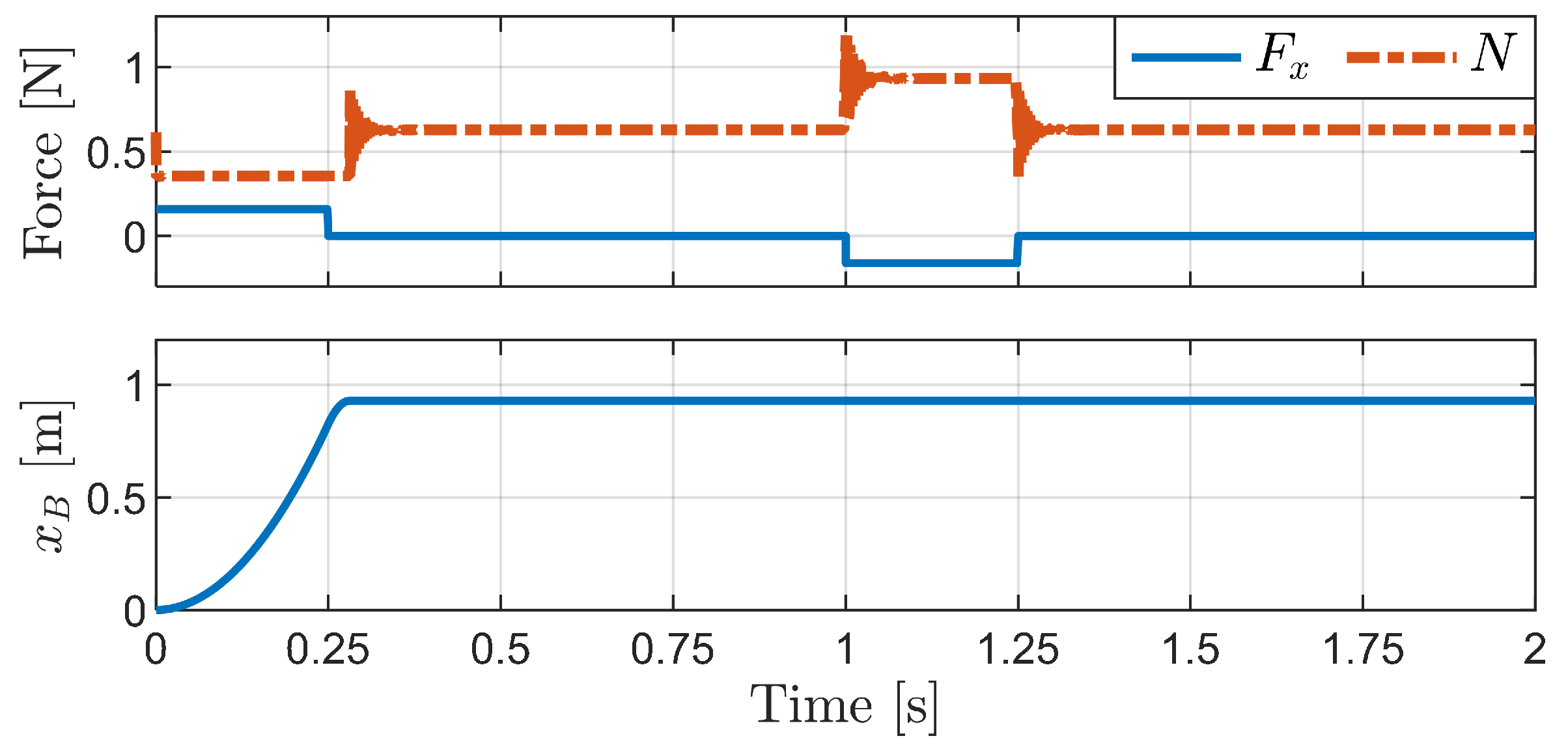
4.1.1. Horizontal External Force
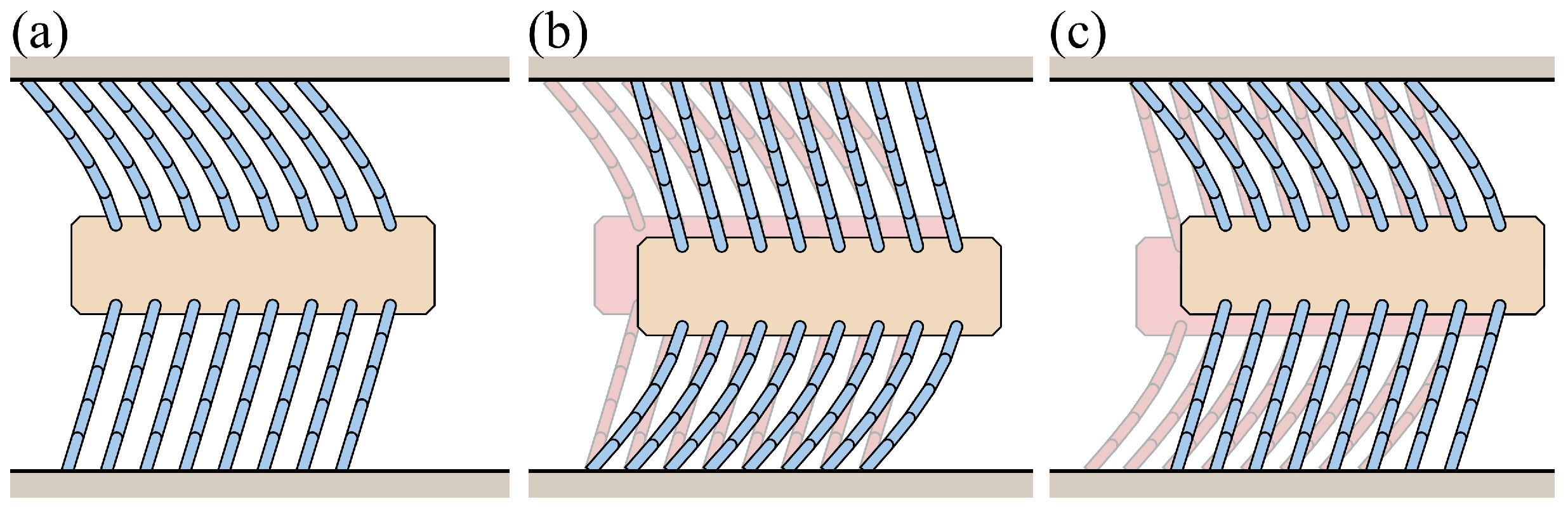
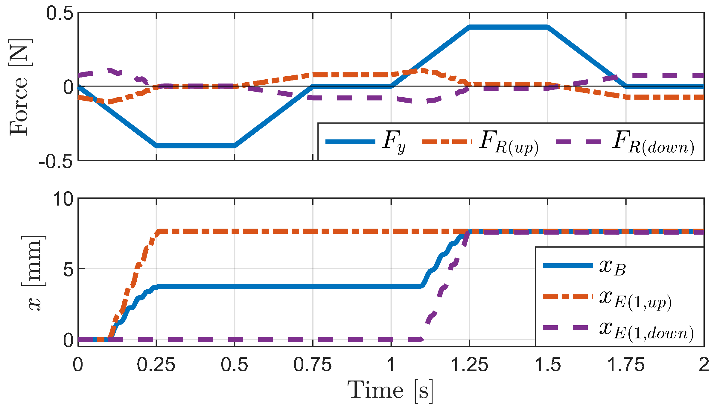
4.1.2. Vertical External Force
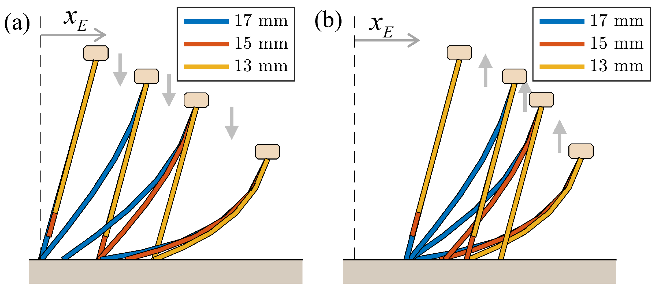
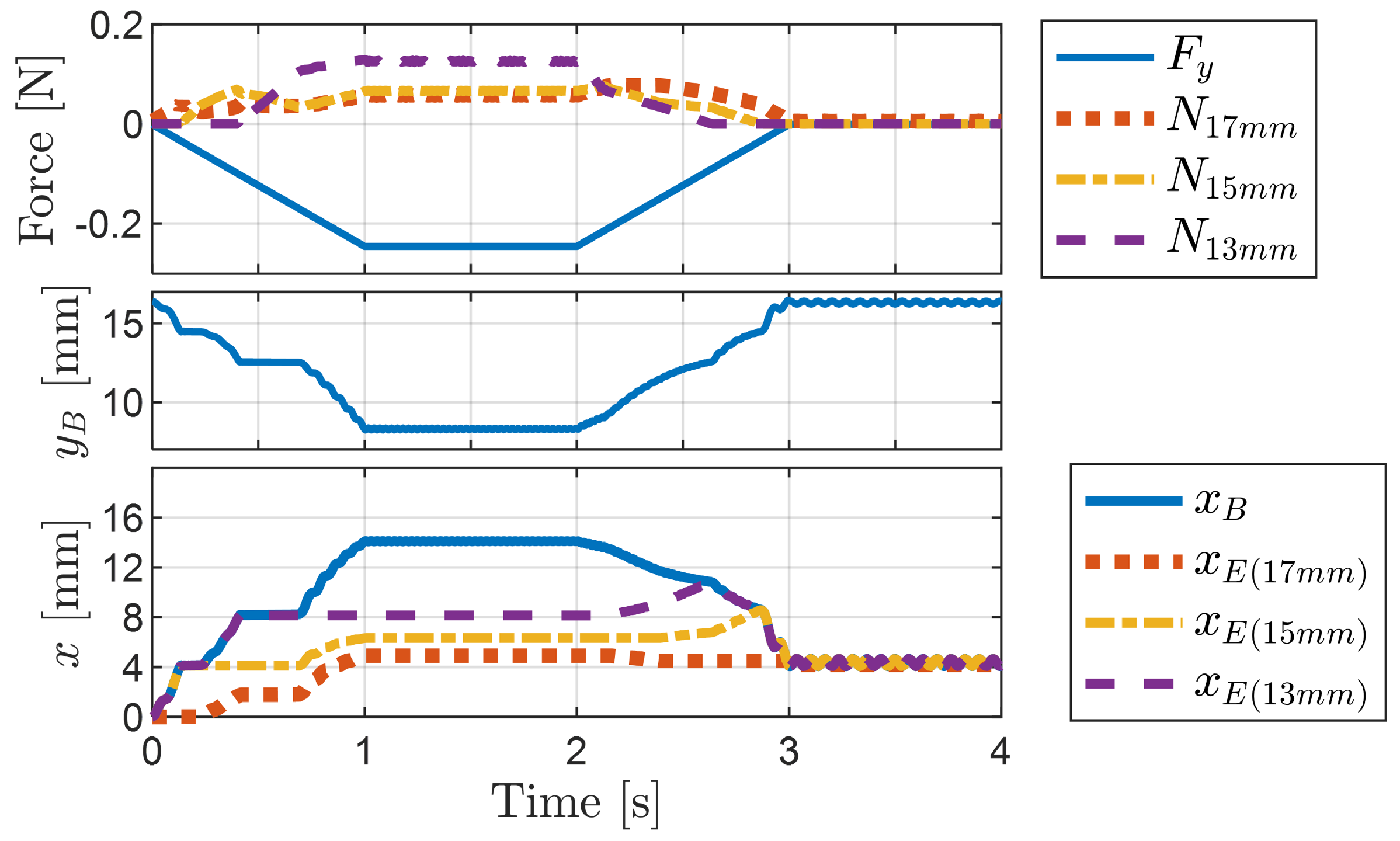
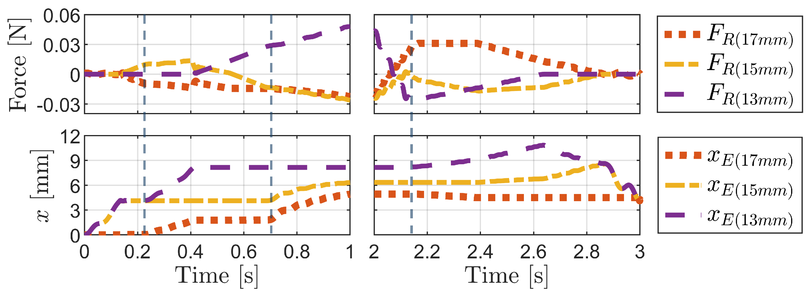
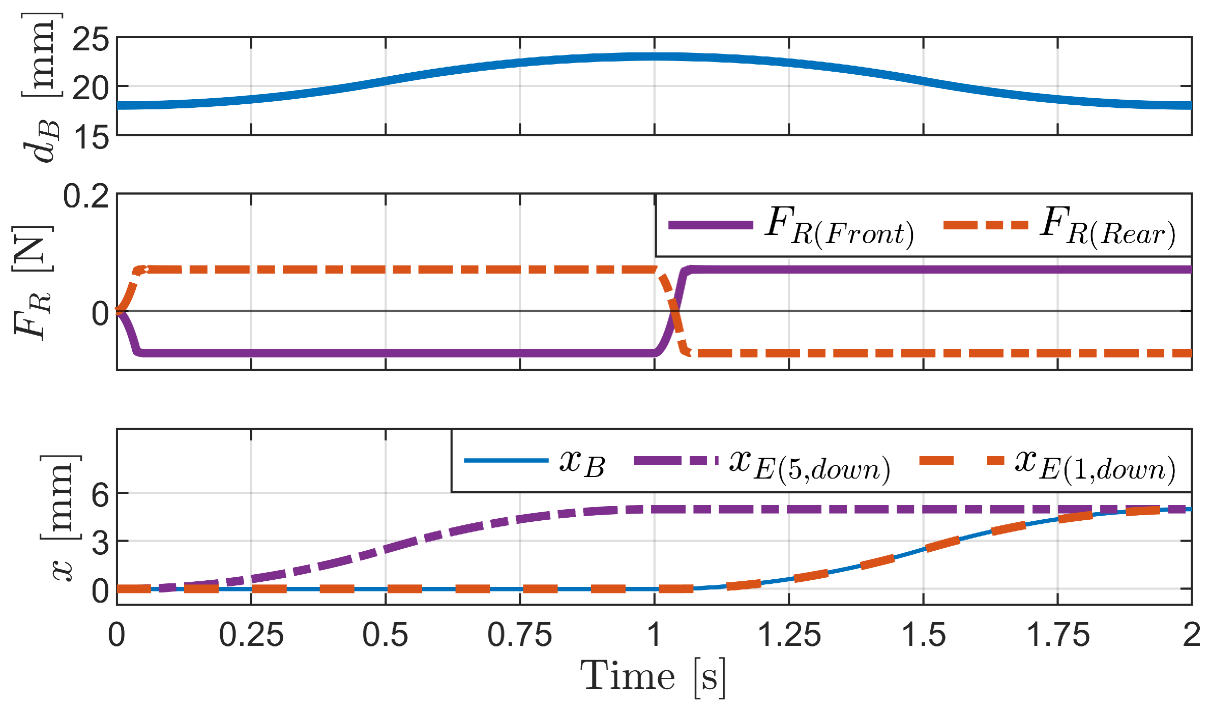
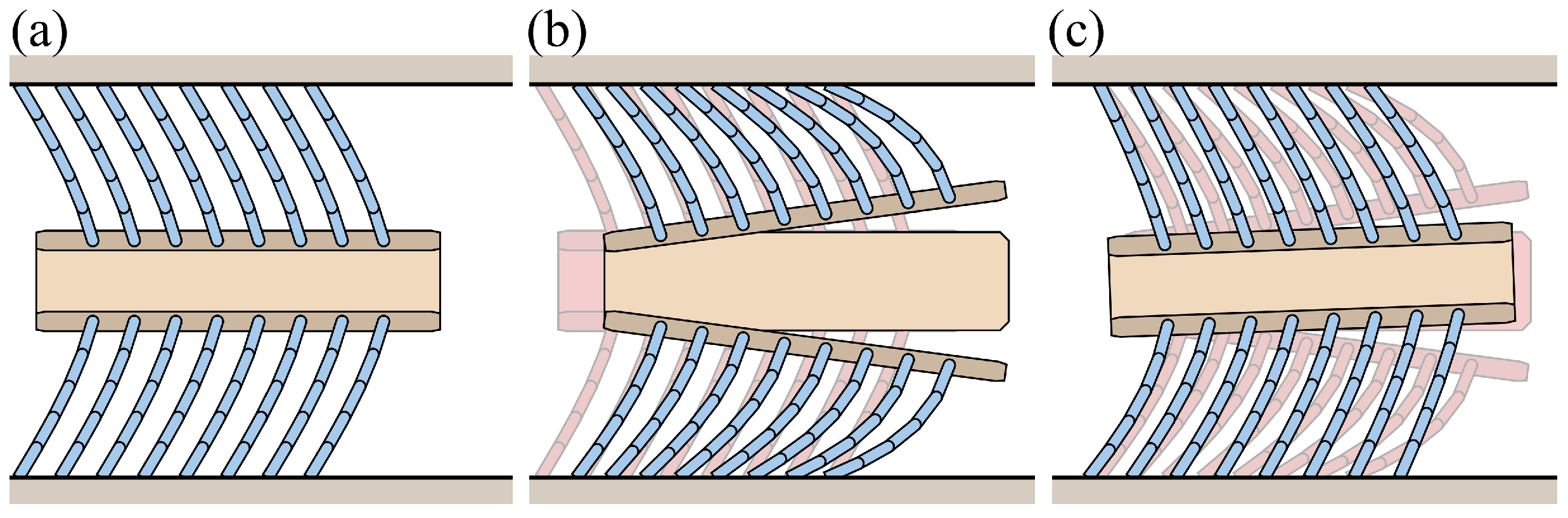
4.1.3. Change in Pipe Height
4.2. Active Locomotion by Internal Actuation
4.2.1. Inchworm Mechanism
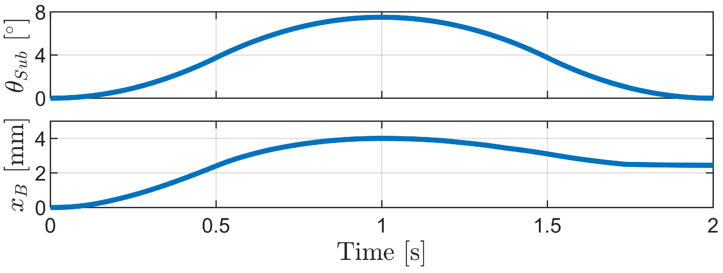
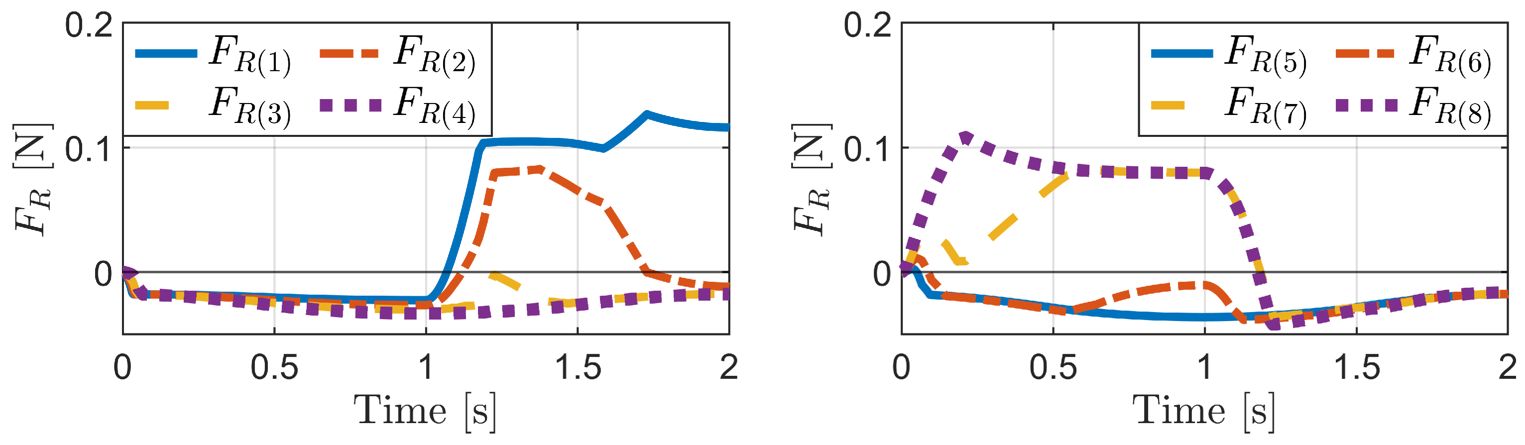
4.2.2. Phase-Difference Mechanism
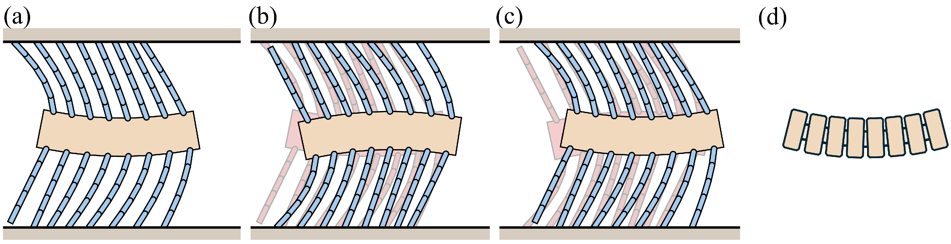
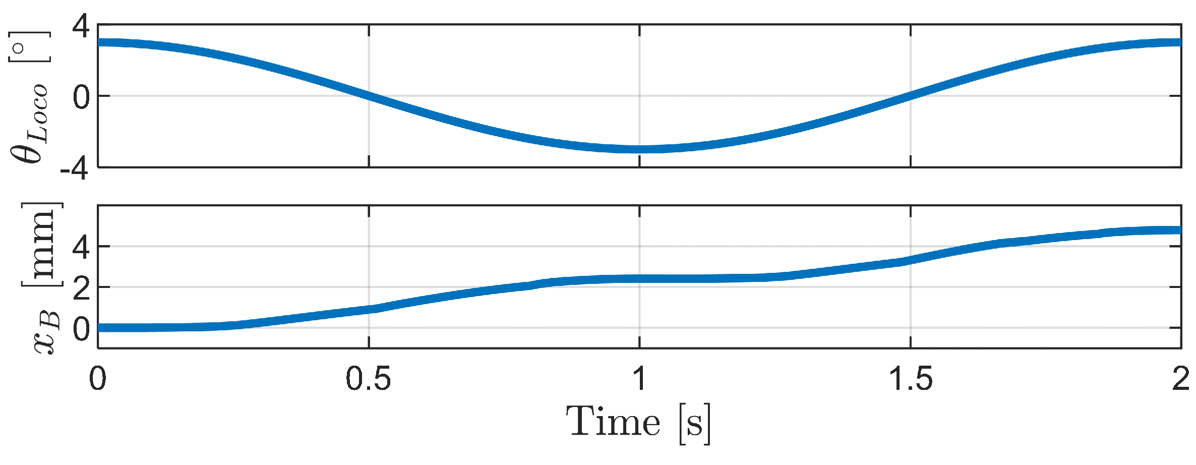
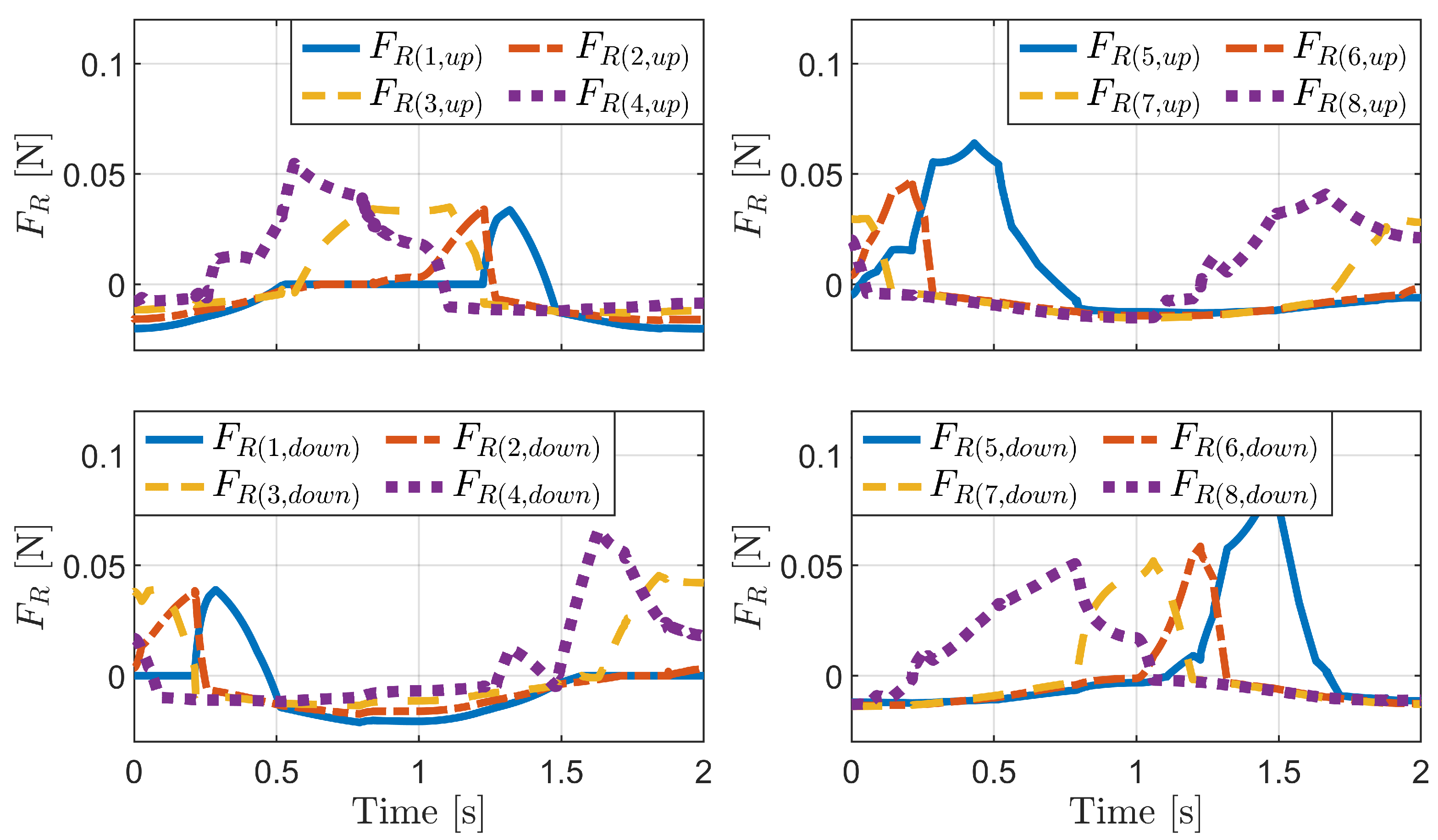
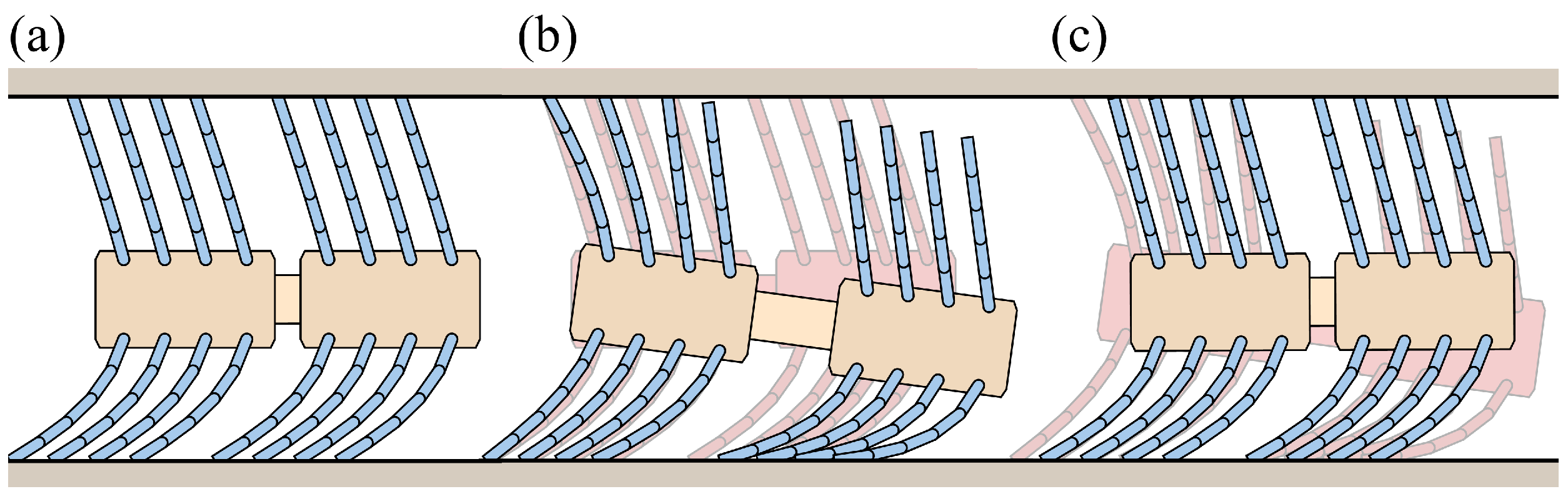
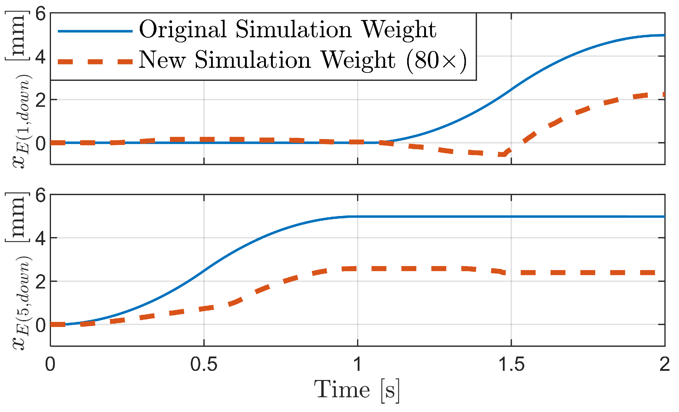
4.2.3. Carangiform Locomotion Mechanism
5. Discussion
6. Conclusions
Author Contributions
Funding
Institutional Review Board Statement
Data Availability Statement
Acknowledgments
Conflicts of Interest
Abbreviations
| PLA | Polylactic Acid; |
| CAD | Computer-Aided Design; |
| FR | Force Ratio; |
| PH | Pipe Height. |
Appendix A. Derivation of Spring Stiffness for Linkage-Spring Model
References
- Kim, Y. Design of a Biomimetic Robot Using Foxtail Mechanism and Carangiform-Locomotion for Various Environments. Master’s Thesis, Yonsei University, Seoul, Republic of Korea, August 2014. [Google Scholar]
- Mita, M.; Kakushima, K.; Ataka, M.; Toshiyoshi, H.; Fujita, H. Foxtail actuators. In Proceedings of the 13th International Conference on Solid-State Sensors, Actuators and Microsystems, Seoul, Republic of Korea, 5–9 June 2005; Volume 1, pp. 680–683. [Google Scholar] [CrossRef]
- Lee, C.W.; Go, D.S.; Heo, M.H.; Lee, D.W.; Yoon, H.U. A soft linear actuator with gentle manipulation mechanism. In Proceedings of the 2019 16th International Conference on Ubiquitous Robots (UR), Jeju, Republic of Korea, 24–27 June 2019; pp. 775–778. [Google Scholar] [CrossRef]
- Lee, M.; Kim, Y.; Leem, S.; Park, J.; Park, S.; Kim, B. Locomotion characteristics of foxtail and foxtail type robot according to acting force. In Proceedings of the 2010 3rd IEEE RAS & EMBS International Conference on Biomedical Robotics and Biomechatronics, Tokyo, Japan, 26–29 September 2010; pp. 604–609. [Google Scholar] [CrossRef]
- Minami, K.; Yano, S. Electrostatic micro actuator with distributed ciliary electrodes (E-Maccel). IEEJ Trans. Sens. Micromach. 2004, 124, 381–386. [Google Scholar] [CrossRef]
- Lu, Q.; Mahtab, B.; Zhao, F.; Song, K.Y.; Feng, Y. Bioinspiration to robot locomotion implementing 3d printed foxtail grass. In Proceedings of the 2021 IEEE International Conference on Robotics and Biomimetics (ROBIO), Sanya, China, 27–31 December2021; pp. 69–73. [Google Scholar] [CrossRef]
- Lee, M.; Kim, Y.; Leem, S.; Kim, B. Locomotion Characteristics of a Foxtail and a Foxtail-like Robot. Trans. Korean Soc. Mech. Eng. A 2010, 34, 1893–1899. [Google Scholar] [CrossRef]
- Choi, Y. Development of a Foxtail Robot Moving in an Irregular Pipeline. Master’s Thesis, Yonsei University, Seoul, Republic of Korea, August 2007. [Google Scholar]
- Wang, Z.; Gu, H. A bristle-based pipeline robot for ill-constraint pipes. IEEE/ASME Trans. Mechatron. 2008, 13, 383–392. [Google Scholar] [CrossRef]
- Lee, D. Design of Foxtail Robot Using Phase Difference Motion for Narrow Space. Master’s Thesis, Yonsei University, Seoul, Republic of Korea, August 2018. [Google Scholar]
- Cicconofri, G.; DeSimone, A. Motility of a model bristle-bot: A theoretical analysis. Int. J. Non-Linear Mech. 2015, 76, 233–239. [Google Scholar] [CrossRef]
- DeSimone, A.; Tatone, A. Crawling Motility Through the Analysis of Model Locomotors: Two Case Studies. Eur. Phys. J. E 2012, 35, 1–8. [Google Scholar] [CrossRef] [PubMed]
- Becker, F.; Börner, S.; Kästner, T.; Lysenko, V.; Zeidis, I.; Zimmermann, K. Spy Bristle Bot—A Vibration-Driven Robot for the Inspection of Pipelines. In Proceedings of the 58th Ilmenau Scientific Colloquium, Ilmenau, Germany, 8–12 September 2014; pp. 1–7. [Google Scholar]
- Becker, F. An Approach to the Dynamics of Vibration-Driven Robots with Bristles. IFAC-Pap. 2015, 48, 842–843. [Google Scholar] [CrossRef]
- Tallapragada, P.; Gandra, C. A Mobile Mathieu Oscillator Model for Vibrational Locomotion of a Bristlebot. J. Mech. Robot. 2021, 13, 054501. [Google Scholar] [CrossRef]
- Kim, D.; Hao, Z.; Mohazab, A.R.; Ansari, A. On the Forward and Backward Motion of Milli-Bristlebots. Int. J. Non-Linear Mech. 2020, 127, 103551. [Google Scholar] [CrossRef]
- Cheng, Q.; Yang, F.; Jiang, H.; Cai, H. Investigation of the friction reduction and anisotropy of seta structure with large deflection cantilever beam model. Tribol. Int. 2022, 172, 107640. [Google Scholar] [CrossRef]
- Adduci, R.; Vermaut, M.; Perrelli, M.; Cosco, F.; Vanpaemel, S.; Naets, F.; Mundo, D. A review of bushing modelling approaches for MultiBody simulations. Mech. Mach. Theory 2024, 191, 105496. [Google Scholar] [CrossRef]
- Wojtyra, M. Modeling of static friction in closed-loop kinematic chains—Uniqueness and parametric sensitivity problems. Multibody Syst. Dyn. 2017, 39, 337–361. [Google Scholar] [CrossRef]
- Lo, Y.L.; Chen, T.C.; Ho, T.L. Design in triangle-profiles and T-profiles of a wirebond using a linkage-spring model. IEEE Trans. Compon. Packag. Technol. 2001, 24, 457–467. [Google Scholar] [CrossRef]
- Chalissery, D.; Schönfeld, D.; Walter, M.; Shklyar, I.; Andrae, H.; Schwörer, C.; Amann, T.; Weisheit, L.; Pretsch, T. Highly shrinkable objects as obtained from 4D printing. Macromol. Mater. Eng. 2022, 307, 2100619. [Google Scholar] [CrossRef]
- Raibert, M.H. Hopping in Legged Systems—Modeling and Simulation for the Two-Dimensional One-Legged Case. IEEE Trans. Syst. Man Cybern. 1984, SMC-14, 451–463. [Google Scholar] [CrossRef]
- Medel, F.; Abad, J.; Esteban, V. Stiffness and damping behavior of 3D printed specimens. Polym. Test. 2022, 109, 107529. [Google Scholar] [CrossRef]
- Trujillo, M.; Corral, L.; Curtin, M.; Abdelkefi, A. Comparative investigations on the dynamical responses of ABS and PLA additively-manufactured beams. Int. J. Non-Linear Mech. 2023, 157, 104558. [Google Scholar] [CrossRef]
- Shiba, M.; Sato, R.; Fukuda, T. A comparison of mechanical characteristics among Setaria viridis var. minor, Setaria italica, and Setaria× pycnocoma species of the family Poaceae. Plant Species Biol. 2024, 39, 51–58. [Google Scholar] [CrossRef]


| Parameter | Value | Units |
|---|---|---|
| Material | PLA | |
| Bristle length L | 15 | mm |
| Bristle reference angle | 15 | degree (°) |
| Bristle thickness h | 0.4 | mm |
| Bristle width b | 0.4 | mm |
| PLA density | 1240 | kg/m3 |
| PLA damping ratio | 3 | % |
| Kinetic friction coefficient | 0.4 | |
| Characteristic velocity | 0.001 | mm/s |
| Area moment of inertia I | 2.13 × 10⁻³ | mm4 |
| Young’s modulus of PLA E | 3500 | MPa |
| Ground stiffness | 104 | N/m |
| Ground damping | 75 | N·s/m |
Disclaimer/Publisher’s Note: The statements, opinions and data contained in all publications are solely those of the individual author(s) and contributor(s) and not of MDPI and/or the editor(s). MDPI and/or the editor(s) disclaim responsibility for any injury to people or property resulting from any ideas, methods, instructions or products referred to in the content. |
© 2024 by the authors. Licensee MDPI, Basel, Switzerland. This article is an open access article distributed under the terms and conditions of the Creative Commons Attribution (CC BY) license (https://creativecommons.org/licenses/by/4.0/).
Share and Cite
Lee, J.; Jeong, H.; Kim, T.; Yang, H. Dynamic Analysis of the Locomotion Mechanism in Foxtail Robots: Frictional Anisotropy and Bristle Diversity. Biomimetics 2024, 9, 311. https://doi.org/10.3390/biomimetics9060311
Lee J, Jeong H, Kim T, Yang H. Dynamic Analysis of the Locomotion Mechanism in Foxtail Robots: Frictional Anisotropy and Bristle Diversity. Biomimetics. 2024; 9(6):311. https://doi.org/10.3390/biomimetics9060311
Chicago/Turabian StyleLee, Jaegak, Hyemi Jeong, Taehyun Kim, and Hyunseok Yang. 2024. "Dynamic Analysis of the Locomotion Mechanism in Foxtail Robots: Frictional Anisotropy and Bristle Diversity" Biomimetics 9, no. 6: 311. https://doi.org/10.3390/biomimetics9060311
APA StyleLee, J., Jeong, H., Kim, T., & Yang, H. (2024). Dynamic Analysis of the Locomotion Mechanism in Foxtail Robots: Frictional Anisotropy and Bristle Diversity. Biomimetics, 9(6), 311. https://doi.org/10.3390/biomimetics9060311