
Design of Low-Cost Modular Bio-Inspired Electric–Pneumatic Actuator (EPA)-Driven Legged Robots
 , ,
, , 

Abstract
1. Introduction
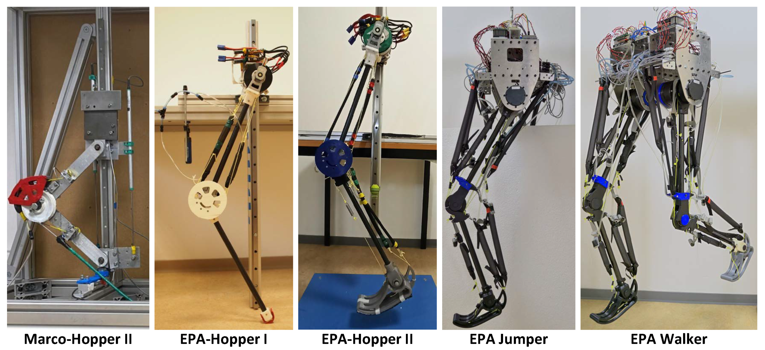
2. Overview of Previous EPA-Robot Developments
2.1. Electric–Pneumatic Actuation
2.2. Previous Iterations of EPA Robots
2.3. Control Approaches
3. EPA-Jumper and EPA-Walker Design
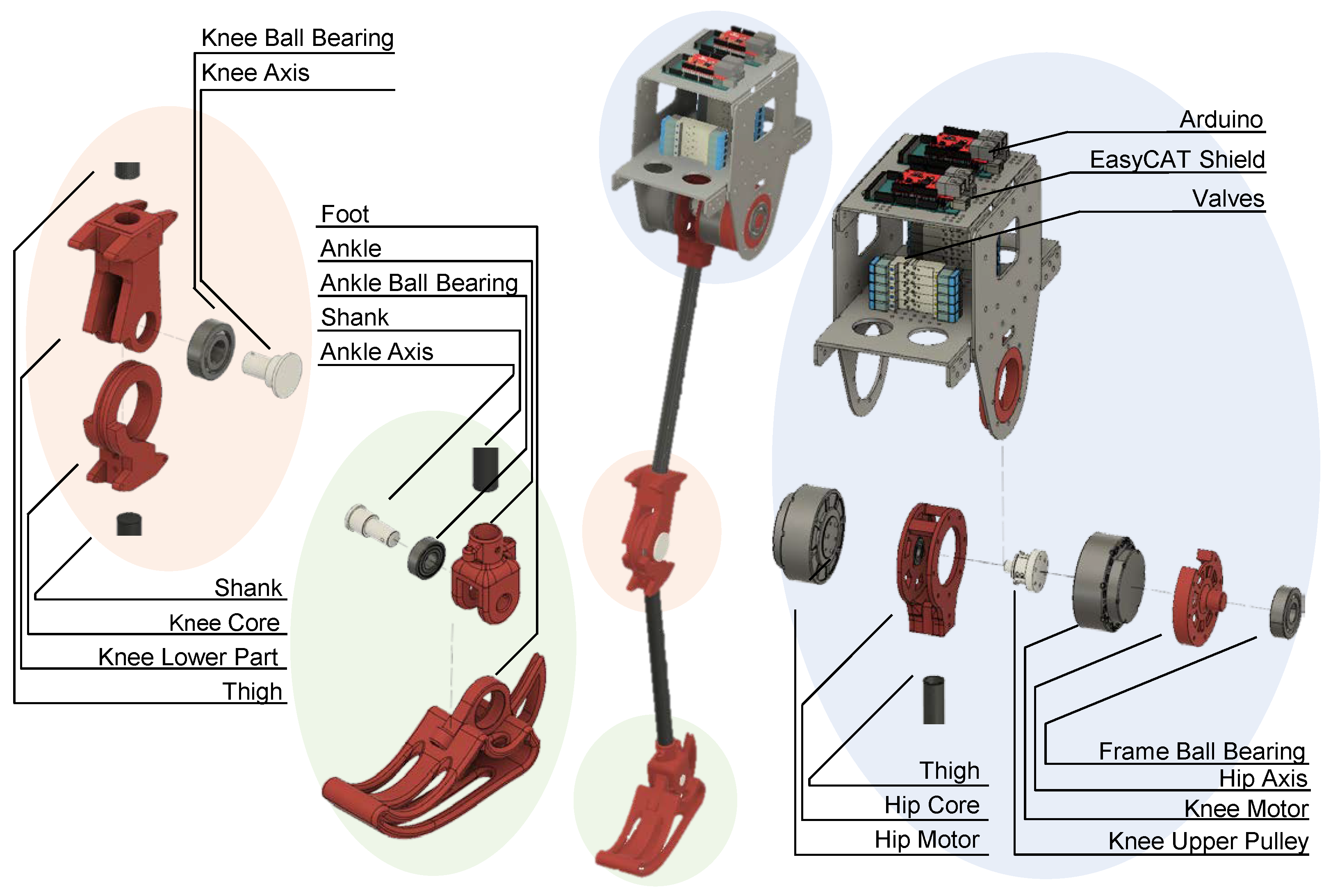
3.1. Mechanical Design
3.1.1. Trunk
3.1.2. Hip
3.1.3. Knee
3.1.4. Ankle
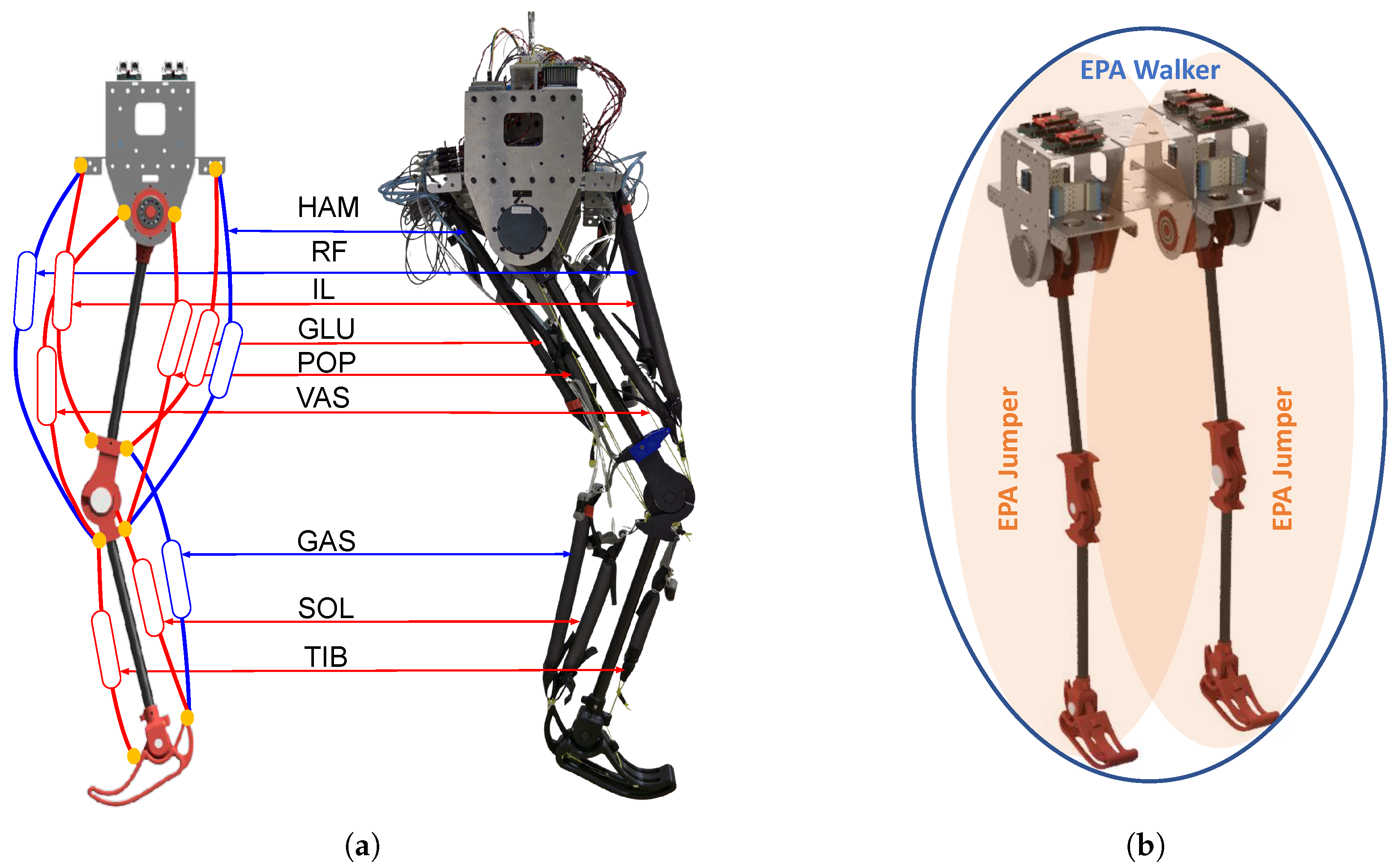
3.2. Actuation
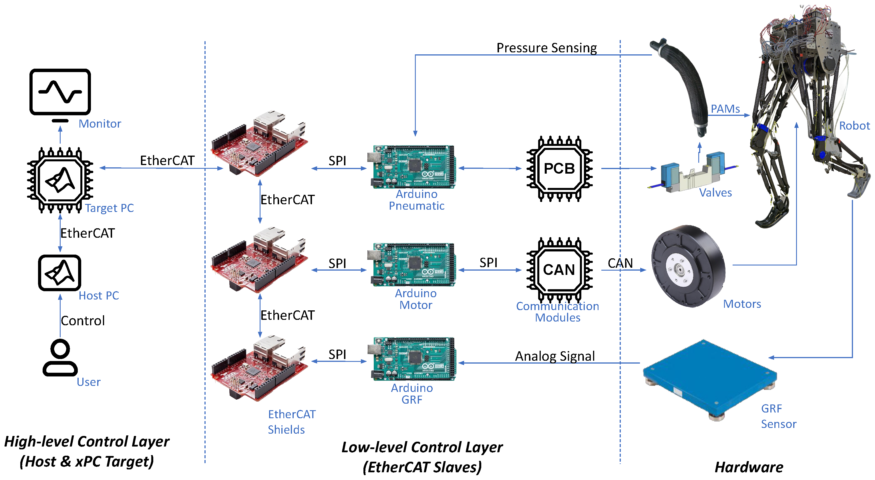
3.3. Electrical Design
3.3.1. High-Level Control Layer
3.3.2. Low-Level Control Layer
4. Results
4.1. Mechanical Properties: Robot vs. Human
4.2. Preliminary Results of EPA Jumper
4.3. Hopping Performance with Different EPA Robots
5. Discussion
5.1. Morphological Similarity and Modularity
5.2. EPA Actuation and Control Embodiment
5.3. Reverse Engineering the Biological Locomotor System
5.4. Outlook
Supplementary Materials
Author Contributions
Funding
Data Availability Statement
Conflicts of Interest
References
- Sharbafi, M.A.; Seyfarth, A. Bioinspired Legged Locomotion: Models, Concepts, Control and Applications; Butterworth-Heinemann: Oxford, UK, 2017. [Google Scholar]
- Şafak, K.K.; Baturalp, T.B.; Bozkurt, S. Parametric Design and Prototyping of a Low-Power Planar Biped Robot. Biomimetics 2023, 8, 346. [Google Scholar] [CrossRef] [PubMed]
- Verrelst, B.; Ham, R.V.; Vanderborght, B.; Daerden, F.; Lefeber, D.; Vermeulen, J. The pneumatic biped “Lucy” actuated with pleated pneumatic artificial muscles. Auton. Robot. 2005, 18, 201–213. [Google Scholar] [CrossRef]
- Badri-Spröwitz, A.; Aghamaleki Sarvestani, A.; Sitti, M.; Daley, M.A. BirdBot achieves energy-efficient gait with minimal control using avian-inspired leg clutching. Sci. Robot. 2022, 7, eabg4055. [Google Scholar] [CrossRef] [PubMed]
- Wang, K.; Marsh, D.; Saputra, R.P.; Chappell, D.; Jiang, Z.; Raut, A.; Kon, B.; Kormushev, P. Design and control of SLIDER: An ultra-lightweight, knee-less, low-cost bipedal walking robot. In Proceedings of the 2020 IEEE/RSJ International Conference on Intelligent Robots and Systems (IROS), Las Vegas, NV, USA, 24 October 2020–24 January 2021; IEEE: Piscataway, NJ, USA, 2020; pp. 3488–3495. [Google Scholar]
- Wolfen, S.; Walter, J.; Günther, M.; Haeufle, D.F.; Schmitt, S. Bioinspired pneumatic muscle spring units mimicking the human motion apparatus: Benefits for passive motion range and joint stiffness variation in antagonistic setups. In Proceedings of the 2018 25th International Conference on Mechatronics and Machine Vision in Practice (M2VIP), Stuttgart, Germany, 20–22 November 2018; IEEE: Piscataway, NJ, USA, 2018; pp. 1–6. [Google Scholar]
- Trivedi, U.; Menychtas, D.; Alqasemi, R.; Dubey, R. Biomimetic Approaches for Human Arm Motion Generation: Literature Review and Future Directions. Sensors 2023, 23, 3912. [Google Scholar] [CrossRef] [PubMed]
- Lenzi, T.; Vitiello, N.; McIntyre, J.; Roccella, S.; Carrozza, M.C. A robotic model to investigate human motor control. Biol. Cybern. 2011, 105, 1–19. [Google Scholar] [CrossRef] [PubMed]
- Pratt, G.A.; Williamson, M.M. Series elastic actuators. In Proceedings of the 1995 IEEE/RSJ International Conference on Intelligent Robots and Systems, Human Robot Interaction and Cooperative Robots, Pittsburgh, PA, USA, 5–9 August 1995; IEEE: Piscataway, NJ, USA, 1995; Volume 1, pp. 399–406. [Google Scholar]
- Hurst, J.W.; Chestnutt, J.E.; Rizzi, A.A. An actuator with physically variable stiffness for highly dynamic legged locomotion. In Proceedings of the IEEE International Conference on Robotics and Automation, ICRA’04, New Orleans, LA, USA, 26 April–1 May 2004; IEEE: Piscataway, NJ, USA, 2004; Volume 5, pp. 4662–4667. [Google Scholar]
- Farley, C.T.; Gonzalez, O. Leg stiffness and stride frequency in human running. J. Biomech. 1996, 29, 181–186. [Google Scholar] [CrossRef] [PubMed]
- Ferris, D.P.; Louie, M.; Farley, C.T. Running in the real world: Adjusting leg stiffness for different surfaces. Proc. R. Soc. Lond. Ser. B Biol. Sci. 1998, 265, 989–994. [Google Scholar] [CrossRef]
- Seok, S.; Wang, A.; Otten, D.; Kim, S. Actuator design for high force proprioceptive control in fast legged locomotion. In Proceedings of the 2012 IEEE/RSJ International Conference on Intelligent Robots and Systems, Vilamoura-Algarve, Portugal, 7–12 October 2012; IEEE: Piscataway, NJ, USA, 2012; pp. 1970–1975. [Google Scholar]
- Ott, C.; Albu-Schaffer, A.; Kugi, A.; Hirzinger, G. On the passivity-based impedance control of flexible joint robots. IEEE Trans. Robot. 2008, 24, 416–429. [Google Scholar] [CrossRef]
- Guenther, F.; Vu, H.Q.; Iida, F. Improving legged robot hopping by using coupling-based series elastic actuation. IEEE/ASME Trans. Mechatron. 2019, 24, 413–423. [Google Scholar] [CrossRef]
- Sharbafi, M.A.; Rode, C.; Kurowski, S.; Scholz, D.; Möckel, R.; Radkhah, K.; Zhao, G.; Rashty, A.M.; von Stryk, O.; Seyfarth, A. A new biarticular actuator design facilitates control of leg function in BioBiped3. Bioinspir. Biomim. 2016, 11, 046003. [Google Scholar] [CrossRef]
- Kim, B.S.; Song, J.B.; Park, J.J. A serial-type dual actuator unit with planetary gear train: Basic design and applications. IEEE/ASME Trans. Mechatron. 2009, 15, 108–116. [Google Scholar]
- Verstraten, T.; Furnémont, R.; Beckerle, P.; Vanderborght, B.; Lefeber, D. A hopping robot driven by a series elastic dual-motor actuator. IEEE Robot. Autom. Lett. 2019, 4, 2310–2316. [Google Scholar] [CrossRef]
- Tonietti, G.; Schiavi, R.; Bicchi, A. Design and control of a variable stiffness actuator for safe and fast physical human/robot interaction. In Proceedings of the 2005 IEEE International Conference on Robotics and Automation, Barcelona, Spain, 18–22 April 2005; IEEE: Piscataway, NJ, USA, 2005; pp. 526–531. [Google Scholar]
- Galloway, K.C.; Clark, J.E.; Koditschek, D.E. Design of a tunable stiffness composite leg for dynamic locomotion. In Proceedings of the International Design Engineering Technical Conferences and Computers and Information in Engineering Conference, San Diego, CA, USA, 30 August–2 September 2009; Volume 49040, pp. 215–222. [Google Scholar]
- Zhao, G.; Mohseni, O.; Murcia, M.; Seyfarth, A.; Sharbafi, M.A. Exploring the effects of serial and parallel elasticity on a hopping robot. Front. Neurorobot. 2022, 16, 919830. [Google Scholar] [CrossRef] [PubMed]
- Ahmad Sharbafi, M.; Shin, H.; Zhao, G.; Hosoda, K.; Seyfarth, A. Electric-pneumatic actuator: A new muscle for locomotion. Actuators 2017, 6, 30. [Google Scholar] [CrossRef]
- Wisse, M.; Van der Linde, R.Q. Delft Pneumatic Bipeds; Springer Science & Business Media: Berlin/Heidelberg, Germany, 2007; Volume 34. [Google Scholar]
- Shin, D.; Sardellitti, I.; Park, Y.L.; Khatib, O.; Cutkosky, M. Design and control of a bio-inspired human-friendly robot. Int. J. Robot. Res. 2010, 29, 571–584. [Google Scholar] [CrossRef]
- Ogawa, K.; Narioka, K.; Hosoda, K. Development of whole-body humanoid “Pneumat-BS” with pneumatic musculoskeletal system. In Proceedings of the 2011 IEEE/RSJ International Conference on Intelligent Robots and Systems, San Francisco, CA, USA, 25–30 September 2011; IEEE: Piscataway, NJ, USA, 2011; pp. 4838–4843. [Google Scholar]
- Sardellitti, I.; Park, J.; Shin, D.; Khatib, O. Air muscle controller design in the distributed macro-mini (DM 2) actuation approach. In Proceedings of the 2007 IEEE/RSJ International Conference on Intelligent Robots and Systems, San Diego, CA, USA, 29 October–2 November 2007; IEEE: Piscataway, NJ, USA, 2007; pp. 1822–1827. [Google Scholar]
- Hyon, S.H.; Morimoto, J.; Matsubara, T.; Noda, T.; Kawato, M. XoR: Hybrid drive exoskeleton robot that can balance. In Proceedings of the 2011 IEEE/RSJ International Conference on Intelligent Robots and Systems, San Francisco, CA, USA, 25–30 September 2011; IEEE: Piscataway, NJ, USA, 2011; pp. 3975–3981. [Google Scholar]
- Sharbafi, M.A.; Yazdanpanah, M.J.; Ahmadabadi, M.N.; Seyfarth, A. Parallel compliance design for increasing robustness and efficiency in legged locomotion—Theoretical background and applications. IEEE/ASME Trans. Mechatron. 2020, 26, 335–346. [Google Scholar]
- Galljamov, R.; Ahmadi, A.; Mohseni, O.; Seyfarth, A.; Beckerle, P.; Sharbafi, M.A. Adjustable Compliance and Force Feedback as Key Elements for Stable and Efficient Hopping. IEEE Robot. Autom. Lett. 2021, 6, 6797–6804. [Google Scholar] [CrossRef]
- Mohseni, O.; Rashty, A.M.N.; Seyfarth, A.; Hosoda, K.; Sharbafi, M.A. Bioinspired legged robot design via blended physical and virtual impedance control. J. Intell. Robot. Syst. 2022, 105, 22. [Google Scholar] [CrossRef]
- Mohseni, O.; Schmidt, P.; Seyfarth, A.; Sharbafi, M.A. Vastus and Gastrocnemius improve hopping efficiency and joints synchronicity at different frequencies: A robotic study. In Proceedings of the 2022 IEEE/RSJ International Conference on Intelligent Robots and Systems (IROS), Kyoto, Japan, 23–27 October 2022; IEEE: Piscataway, NJ, USA, 2022; pp. 11947–11954. [Google Scholar]
- Kim, S.; Laschi, C.; Trimmer, B. Soft robotics: A bioinspired evolution in robotics. Trends Biotechnol. 2013, 31, 287–294. [Google Scholar] [CrossRef]
- Sun, Y.; Zong, C.; Pancheri, F.; Chen, T.; Lueth, T.C. Design of topology optimized compliant legs for bio-inspired quadruped robots. Sci. Rep. 2023, 13, 4875. [Google Scholar] [CrossRef]
- Zhang, J.; Liu, Q.; Zhou, J.; Song, A. Crab-inspired compliant leg design method for adaptive locomotion of a multi-legged robot. Bioinspir. Biomim. 2022, 17, 025001. [Google Scholar] [CrossRef]
- Hauser, H.; Nanayakkara, T.; Forni, F. Leveraging Morphological Computation for Controlling Soft Robots: Learning from Nature to Control Soft Robots. IEEE Control Syst. Mag. 2023, 43, 114–129. [Google Scholar] [CrossRef]
- Nasonov, K.V.; Ivolga, D.V.; Borisov, I.I.; Kolyubin, S.A. Computational design of closed-chain linkages: Hopping robot driven by morphological computation. In Proceedings of the 2023 IEEE International Conference on Robotics and Automation (ICRA), London, UK, 29 May–2 June 2003; IEEE: Piscataway, NJ, USA, 2023; pp. 7419–7425. [Google Scholar]
- Mohseni, O.; Gagey, F.; Zhao, G.; Seyfarth, A.; Sharbafi, M.A. How far are Pneumatic Artificial Muscles from biological muscles? In Proceedings of the 2020 IEEE International Conference on Robotics and Automation (ICRA), Paris, France, 31 May–31 August 2020; IEEE: Piscataway, NJ, USA, 2020; pp. 1909–1915. [Google Scholar]
- Klute, G.K.; Czerniecki, J.M.; Hannaford, B. Artificial muscles: Actuators for biorobotic systems. Int. J. Robot. Res. 2002, 21, 295–309. [Google Scholar] [CrossRef]
- Duysens, J.; Forner-Cordero, A. Walking with perturbations: A guide for biped humans and robots. Bioinspir. Biomim. 2018, 13, 061001. [Google Scholar] [CrossRef]
- Hunter, I.W.; Hollerbach, J.M.; Ballantyne, J. A comparative analysis of actuator technologies for robotics. Robot. Rev. 1991, 2, 299–342. [Google Scholar]
- Klute, G.K.; Czerniecki, J.M.; Hannaford, B. McKibben artificial muscles: Pneumatic actuators with biomechanical intelligence. In Proceedings of the 1999 IEEE/ASME International Conference on Advanced Intelligent Mechatronics (Cat. No. 99TH8399), Atlanta, GA, USA, 19–23 September 1999; IEEE: Piscataway, NJ, USA, 1999; pp. 221–226. [Google Scholar]
- Andrikopoulos, G.; Nikolakopoulos, G.; Manesis, S. A survey on applications of pneumatic artificial muscles. In Proceedings of the 2011 19th Mediterranean Conference on Control & Automation (MED), Corfu, Greece, 20–23 June 2011; IEEE: Piscataway, NJ, USA, 2011; pp. 1439–1446. [Google Scholar]
- Kim, N.H.; Kim, J.M.; Khatib, O.; Shin, D. Design optimization of hybrid actuation combining macro-mini actuators. Int. J. Precis. Eng. Manuf. 2017, 18, 519–527. [Google Scholar] [CrossRef]
- Rouzbeh, B.; Bone, G.M.; Ashby, G.; Li, E. Design, implementation and control of an improved hybrid pneumatic-electric actuator for robot arms. IEEE Access 2019, 7, 14699–14713. [Google Scholar] [CrossRef]
- Nishikawa, K.; Biewener, A.A.; Aerts, P.; Ahn, A.N.; Chiel, H.J.; Daley, M.A.; Daniel, T.L.; Full, R.J.; Hale, M.E.; Hedrick, T.L.; et al. Neuromechanics: An integrative approach for understanding motor control. Integr. Comp. Biol. 2007, 47, 16–54. [Google Scholar] [CrossRef]
- Sharbafi, M.A.; Mohammadi Nejad Rashty, A. Hybrid Electric-Pneumatic Actuator. In Novel Bioinspired Actuator Designs for Robotics; Springer: Cham, Switzerland, 2021; pp. 55–61. [Google Scholar]
- Oehlke, J.; Beckerle, P.; Seyfarth, A.; Sharbafi, M.A. Human-like hopping in machines: Feedback-versus feed-forward-controlled motions. Biol. Cybern. 2019, 113, 227–238. [Google Scholar] [CrossRef]
- Kuitunen, S.; Ogiso, K.; Komi, P. Leg and joint stiffness in human hopping. Scand. J. Med. Sci. Sport. 2011, 21, e159–e167. [Google Scholar] [CrossRef]
- Rashty, A.M.N.; Grimmer, M.; Seyfarth, A. Hopping frequency influences elastic energy reuse with joint series elastic actuators. J. Biomech. 2021, 119, 110319. [Google Scholar]
- Geyer, H.; Herr, H. A muscle-reflex model that encodes principles of legged mechanics produces human walking dynamics and muscle activities. IEEE Trans. Neural Syst. Rehabil. Eng. 2010, 18, 263–273. [Google Scholar] [CrossRef]
- Kalveram, K.T.; Haeufle, D.F.; Seyfarth, A.; Grimmer, S. Energy management that generates terrain following versus apex-preserving hopping in man and machine. Biol. Cybern. 2012, 106, 1–13. [Google Scholar] [CrossRef]
- Pratt, J.; Dilworth, P.; Pratt, G. Virtual model control of a bipedal walking robot. In Proceedings of the International Conference on Robotics and Automation, Albuquerque, NM, USA, 25 April 1997; IEEE: Piscataway, NJ, USA, 1997; Volume 1, pp. 193–198. [Google Scholar]
- Prochazka, A.; Gillard, D.; David.; Bennett, J.; Gillard, D. Positive force feedback control of muscles. J. Neurophysiol. 1997, 77, 3226–3236. [Google Scholar] [CrossRef]
- Geyer, H.; Seyfarth, A.; Blickhan, R. Positive force feedback in bouncing gaits? Proc. R. Soc. Lond. Ser. B Biol. Sci. 2003, 270, 2173–2183. [Google Scholar] [CrossRef]
- Schumacher, C.; Seyfarth, A. Sensor-motor maps for describing linear reflex composition in hopping. Front. Comput. Neurosci. 2017, 11, 108. [Google Scholar] [CrossRef]
- Zhao, G.; Szymanski, F.; Seyfarth, A. Bio-inspired neuromuscular reflex based hopping controller for a segmented robotic leg. Bioinspir. Biomim. 2020, 15, 026007. [Google Scholar] [CrossRef]
- Sharbafi, M.A.; Seyfarth, A. FMCH: A new model to explain postural control in human walking. In Proceedings of the IEEE/RSJ International conference on Intelligent Robots and Systems (IROS), Hamburg, Germany, 28 September–3 October 2015. [Google Scholar]
- Dietz, V.; Leenders, K.; Colombo, G. Leg muscle activation during gait in Parkinson’s disease: Influence of body unloading. Electroencephalogr. Clin. Neurophysiol./Electromyogr. Mot. Control 1997, 105, 400–405. [Google Scholar] [CrossRef]
- Dietz, V.H.; Mueller, R.; Colombo, G. Locomotor activity in spinal man: Significance of afferent input from joint and load receptors. Brain J. Neurol. 2002, 125 Pt 12, 2626–2634. [Google Scholar] [CrossRef]
- Dietz, V.; Duysens, J. Significance of load receptor input during locomotion: A review. Gait Posture 2000, 11, 102–110. [Google Scholar] [CrossRef]
- Kenneally, G.; De, A.; Koditschek, D.E. Design principles for a family of direct-drive legged robots. IEEE Robot. Autom. Lett. 2016, 1, 900–907. [Google Scholar] [CrossRef]
- Beckerle, P.; Verstraten, T.; Mathijssen, G.; Furnémont, R.; Vanderborght, B.; Lefeber, D. Series and parallel elastic actuation: Influence of operating positions on design and control. IEEE/ASME Trans. Mechatron. 2017, 22, 521–529. [Google Scholar] [CrossRef]
- Verstraten, T.; Beckerle, P.; Furnémont, R.; Mathijssen, G.; Vanderborght, B.; Lefeber, D. Series and parallel elastic actuation: Impact of natural dynamics on power and energy consumption. Mech. Mach. Theory 2016, 102, 232–246. [Google Scholar] [CrossRef]
- Wu, W.L.; Rosenbaum, D.; Su, F.C. The effects of rocker sole and SACH heel on kinematics in gait. Med. Eng. Phys. 2004, 26, 639–646. [Google Scholar] [CrossRef]
- Martin, A.E.; Schmiedeler, J.P. The effects of curved foot design parameters on planar biped walking. In Proceedings of the International Design Engineering Technical Conferences and Computers and Information in Engineering Conference, Chicago, IL, USA, 12–15 August 2012; American Society of Mechanical Engineers: New York, NY, USA, 2012; Volume 45035, pp. 815–824. [Google Scholar]
- Vignesh, P.T.; Art, K.; Human; Resdian, R. Noun Project. Available online: https://thenounproject.com/ (accessed on 20 January 2024).
- Winter, D.A. Biomechanics and Motor Control of Human Movement; John Wiley & Sons: Hoboken, NJ, USA, 2009. [Google Scholar]
- EPA Robots Hopping Experiments. Available online: https://youtu.be/iFTkzVBYaEw (accessed on 29 February 2024).
- Song, S.; Kidziński, Ł.; Peng, X.B.; Ong, C.; Hicks, J.; Levine, S.; Atkeson, C.G.; Delp, S.L. Deep reinforcement learning for modeling human locomotion control in neuromechanical simulation. J. Neuroeng. Rehabil. 2021, 18, 126. [Google Scholar] [CrossRef]
- Mohseni, O.; Berry, A.; Schumacher, C.; Seyfarth, A.; Vallery, H.; Sharbafi, M.A. Mediolateral Upper-body Gyroscopic Moment Perturbations During Walking: Exploring Muscle Activation Patterns and Control Strategies. Res. Sq. 2024. [Google Scholar] [CrossRef]
- Junius, K.; Moltedo, M.; Cherelle, P.; Rodriguez-Guerrero, C.; Vanderborght, B.; Lefeber, D. Biarticular elements as a contributor to energy efficiency: Biomechanical review and application in bio-inspired robotics. Bioinspir. Biomim. 2017, 12, 061001. [Google Scholar] [CrossRef]
- Sylos-Labini, F.; La Scaleia, V.; Cappellini, G.; Dewolf, A.; Fabiano, A.; Solopova, I.A.; Mondì, V.; Ivanenko, Y.; Lacquaniti, F. Complexity of modular neuromuscular control increases and variability decreases during human locomotor development. Commun. Biol. 2022, 5, 1256. [Google Scholar] [CrossRef]
- Maier, B. Scalable biophysical simulations of the neuromuscular system. arXiv 2021, arXiv:2107.07104. [Google Scholar]
- Callebaut, W.; Rasskin-Gutman, D. Modularity: Understanding the Development and Evolution of Natural Complex Systems; MIT Press: Cambridge, MA, USA, 2005. [Google Scholar]
- Full, R.J.; Koditschek, D.E. Templates and anchors: Neuromechanical hypotheses of legged locomotion on land. J. Exp. Biol. 1999, 202, 3325–3332. [Google Scholar] [CrossRef]
- Caluwaerts, K.; D’Haene, M.; Verstraeten, D.; Schrauwen, B. Locomotion without a brain: Physical reservoir computing in tensegrity structures. Artif. Life 2013, 19, 35–66. [Google Scholar] [CrossRef]
- Masuda, Y.; Naniwa, K.; Ishikawa, M.; Osuka, K. On brainless-control approach to soft bodies: A novel method to generate motion patterns by pneumatic reflex devices. In Proceedings of the 21th IFAC World Congress, Berlin, Germany, 11–17 July 2020. [Google Scholar]
- Masuda, Y.; Naniwa, K.; Ishikawa, M.; Osuka, K. Brainless walking: Animal gaits emerge from an actuator characteristic. Front. Robot. AI 2021, 8, 629679. [Google Scholar] [CrossRef]
- Pfeifer, R.; Gómez, G. Morphological computation—Connecting brain, body, and environment. In Creating Brain-like Intelligence; Springer: Berlin/Heidelberg, Germany, 2009; pp. 66–83. [Google Scholar]
- Müller, V.C.; Hoffmann, M. What is morphological computation? On how the body contributes to cognition and control. Artif. Life 2017, 23, 1–24. [Google Scholar] [CrossRef]
- Hauser, H.; Ijspeert, A.J.; Füchslin, R.M.; Pfeifer, R.; Maass, W. Towards a theoretical foundation for morphological computation with compliant bodies. Biol. Cybern. 2011, 105, 355–370. [Google Scholar] [CrossRef]
- Iida, F. Cheap design approach to adaptive behavior: Walking and sensing through body dynamics. In Proceedings of the International Symposium on Adaptive Motion of Animals and Machines, Ilmenau, Germany, 25–30 September 2005; p. 15. [Google Scholar]
- Pfeifer, R.; Lungarella, M.; Iida, F. Self-organization, embodiment, and biologically inspired robotics. Science 2007, 318, 1088–1093. [Google Scholar] [CrossRef] [PubMed]
- Sharbafi, M.A.; Ahmadabadi, M.N.; Yazdanpanah, M.J.; Nejad, A.M.; Seyfarth, A. Compliant hip function simplifies control for hopping and running. In Proceedings of the 2013 IEEE/RSJ International Conference on Intelligent Robots and Systems, Tokyo, Japan, 3–7 November 2013; IEEE: Piscataway, NJ, USA, 2013; pp. 5127–5133. [Google Scholar]
- Sharbafi, M.A.; Maufroy, C.; Ahmadabadi, M.N.; Yazdanpanah, M.J.; Seyfarth, A. Robust hopping based on virtual pendulum posture control. Bioinspir. Biomim. 2013, 8, 036002. [Google Scholar] [CrossRef] [PubMed]
- Sharbafi, M.A.; Seyfarth, A. Stable running by leg force-modulated hip stiffness. In Proceedings of the 5th IEEE RAS/EMBS International Conference on Biomedical Robotics and Biomechatronics, Sao Paulo, Brazil, 12–15 August 2014; IEEE: Piscataway, NJ, USA, 2014; pp. 204–210. [Google Scholar]
- Shin, W.; Kim, J. Switchable compliant actuator with fast stiffness modulation and energy efficient power transmission. Mechatronics 2023, 90, 102929. [Google Scholar] [CrossRef]
- Yan, Y.; Shui, L.; Liu, S.; Liu, Z.; Liu, Y. Terrain Adaptability and Optimum Contact Stiffness of Vibro-bot with Arrayed Soft Legs. Soft Robot. 2022, 9, 981–990. [Google Scholar] [CrossRef]


| Feature | PAM | EM |
|---|---|---|
| Output | Force | Torque |
| Mathematical Model | Non-Linear | Fairly Linear |
| Control Precision | Low | Very High |
| Intrinsic Compliance | Very High | Very Low |
| Power Density | High | Medium |
| Efficiency | High | High |
| Range of Motion | Medium | High |
| Dynamic Response | Slow | High |
| Similarity to Human Actuators | High | Very Low |
| Temperature Working Range | Low | High |
| Noise | High | Very Low |
| Cost | Very Low | Low |
| Size and Weight | Very Low | Low |
| Adaptability | High | Low |
| Component | Model | Amount |
|---|---|---|
| Electric Motors | GIM8115-9 | 2 |
| Valves | SMC SYJ3320 | 9 |
| Pressure Sensors | SMC PSE530 | 9 |
| Force Plate | Kistler Type 9260AA | 1 |
| Ankle Ball Bearing | 6202-2Z | 1 |
| Knee and Trunk Ball Bearing | 6304-RS | 2 |
| Knee Motor Ball Bearing | 6001-RS | 1 |
| Micro-controllers | Arduino Due | 1 |
| - | Arduino Mega 2560 Rev 3 | 2 |
| CAN Bus | MCP2515 | 1 |
| Valve Activation PCB | Custom Made | 1 |
| Ethernet Modules | EasyCat Shield | 3 |
| Target PC | 1 | |
| Host PC | - | 1 |
| PLA | - | - |
| Metal Trunk | - | - |
| Dyneema Rope | - | - |
| Rope Tensioner | - | 1 |
| PAMs | Self-made | 9 |
| Emergency Switch | - | 1 |
| 24 V LiPo Battery | GEA500012S60E | 1 |
| 12 V Power Supply | - | 1 |
| Segment Length [-] | Weight [-] | Inertia (Proximal) [kg·m2] | |||||
|---|---|---|---|---|---|---|---|
| Human | EPA Walker | Human | EPA Walker | Human | EPA Walker | Ratio [-] | |
| Foot | 0.152 | 0.098 | 0.015 | 0.016 | 0.026 | 0.002 | 15.6 |
| Shank | 0.246 | 0.247 | 0.047 | 0.039 | 0.128 | 0.038 | 3.4 |
| Thigh | 0.245 | 0.286 | 0.100 | 0.100 | 0.286 | 0.075 | 3.8 |
| Trunk | 0.288 | 0.141 | 0.678 | 0.690 | 5.850 | 0.168 | 34.8 |
| PAM Pressure [MPa] | Flight Angles [°] | FMCK | ||||||||||
|---|---|---|---|---|---|---|---|---|---|---|---|---|
| IL | RF | GLU | HAM | VAS | POP | TIB | SOL | GAS | Hip | Knee | [°] | |
| 0.25 | 0.25 | 0.3 | 0.4 | 0 | 0 | 0.35 | 0.3 | 0.3 | 10 | 30 | 10 | −0.255 |
Disclaimer/Publisher’s Note: The statements, opinions and data contained in all publications are solely those of the individual author(s) and contributor(s) and not of MDPI and/or the editor(s). MDPI and/or the editor(s) disclaim responsibility for any injury to people or property resulting from any ideas, methods, instructions or products referred to in the content. |
© 2024 by the authors. Licensee MDPI, Basel, Switzerland. This article is an open access article distributed under the terms and conditions of the Creative Commons Attribution (CC BY) license (https://creativecommons.org/licenses/by/4.0/).
Share and Cite
Silva, A.B.; Murcia, M.; Mohseni, O.; Takahashi, R.; Forner-Cordero, A.; Seyfarth, A.; Hosoda, K.; Sharbafi, M.A. Design of Low-Cost Modular Bio-Inspired Electric–Pneumatic Actuator (EPA)-Driven Legged Robots. Biomimetics 2024, 9, 164. https://doi.org/10.3390/biomimetics9030164
Silva AB, Murcia M, Mohseni O, Takahashi R, Forner-Cordero A, Seyfarth A, Hosoda K, Sharbafi MA. Design of Low-Cost Modular Bio-Inspired Electric–Pneumatic Actuator (EPA)-Driven Legged Robots. Biomimetics. 2024; 9(3):164. https://doi.org/10.3390/biomimetics9030164
Chicago/Turabian StyleSilva, Alessandro Brugnera, Marc Murcia, Omid Mohseni, Ryu Takahashi, Arturo Forner-Cordero, Andre Seyfarth, Koh Hosoda, and Maziar Ahmad Sharbafi. 2024. "Design of Low-Cost Modular Bio-Inspired Electric–Pneumatic Actuator (EPA)-Driven Legged Robots" Biomimetics 9, no. 3: 164. https://doi.org/10.3390/biomimetics9030164
APA StyleSilva, A. B., Murcia, M., Mohseni, O., Takahashi, R., Forner-Cordero, A., Seyfarth, A., Hosoda, K., & Sharbafi, M. A. (2024). Design of Low-Cost Modular Bio-Inspired Electric–Pneumatic Actuator (EPA)-Driven Legged Robots. Biomimetics, 9(3), 164. https://doi.org/10.3390/biomimetics9030164