


Biomimetic Study of a Honeycomb Energy Absorption Structure Based on Straw Micro-Porous Structure


Abstract
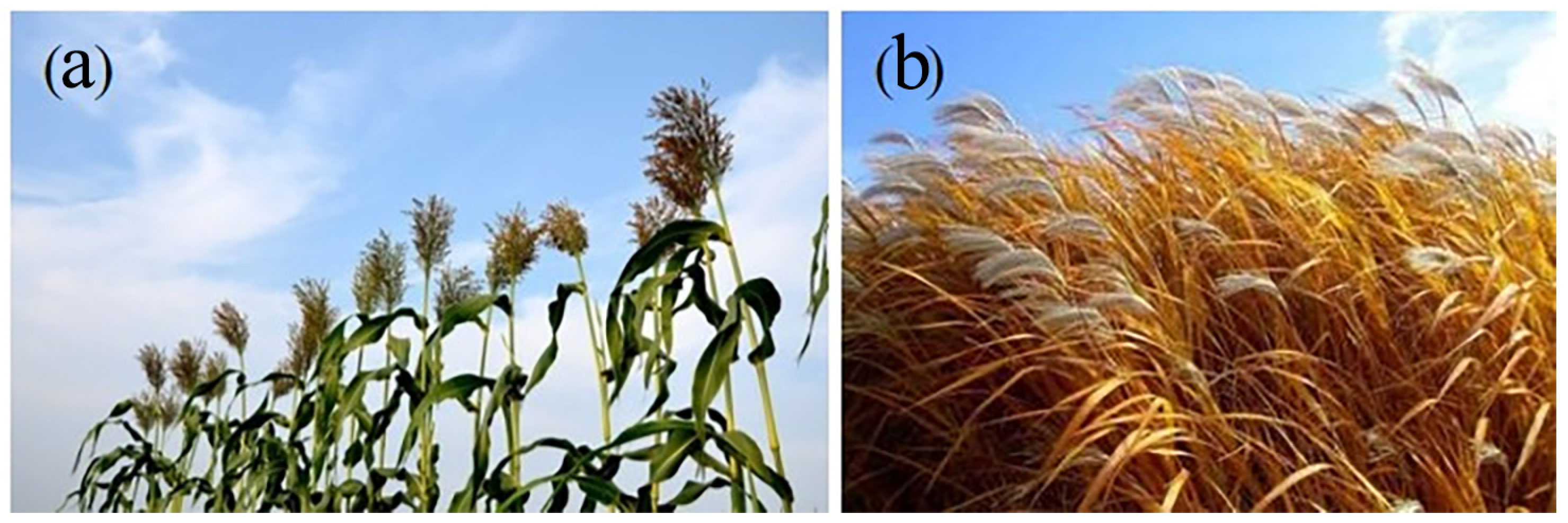
1. Introduction
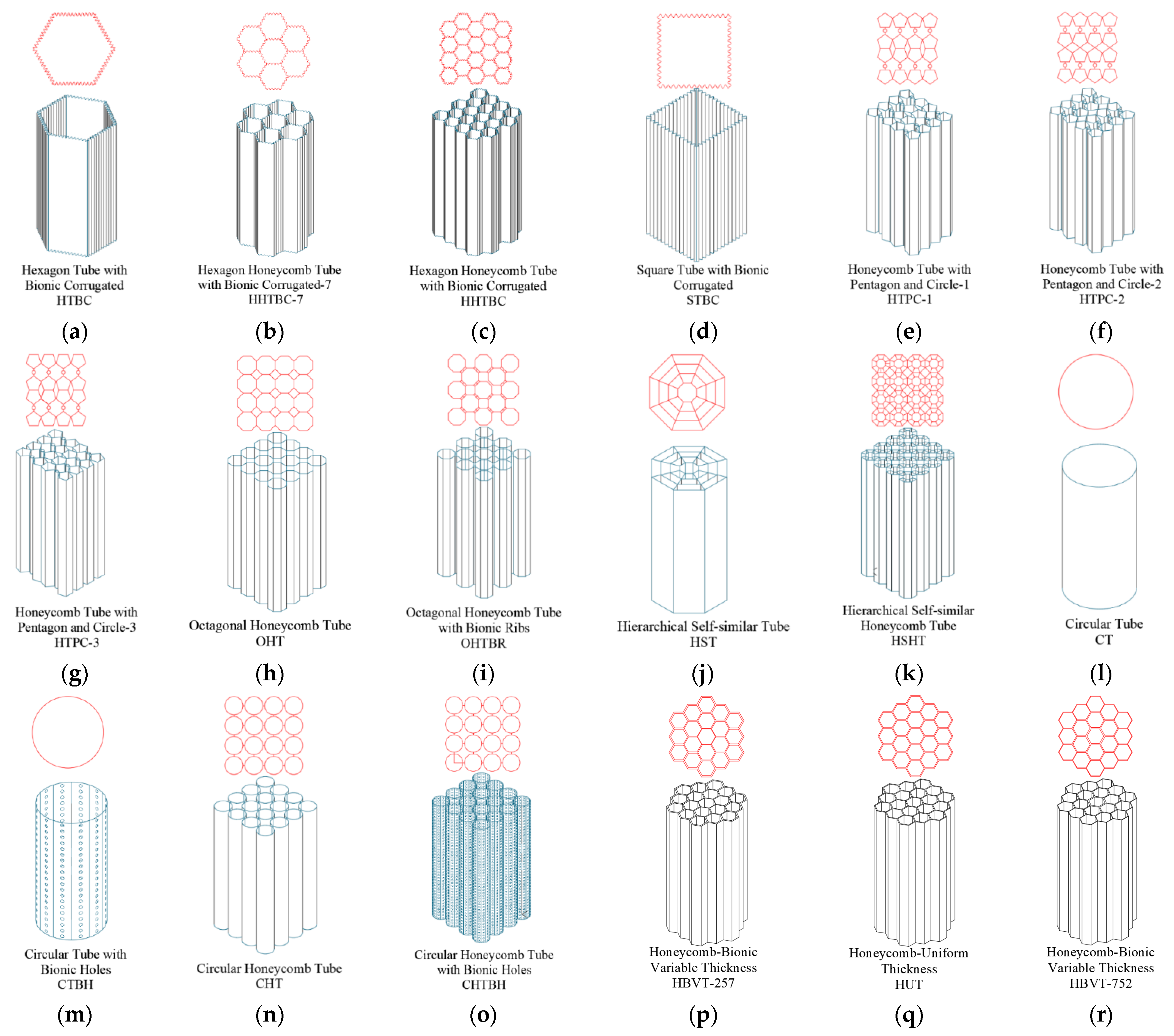
2. Bionic Design of Honeycomb Structures
2.1. Bionic Design of the Cell Edge of a Honeycomb
2.2. Bionic Design of Honeycomb Cell Compound Structure
2.3. Bionic Design of Honeycomb Cell Stiffener Ribs
2.4. Self-Similar Bionic Design of a Honeycomb Cell
2.5. Cellular Bionic Porous Design
2.6. Cellular Gradient Bionic Design
3. FEA Analysis
3.1. The FE Model
3.2. The Energy Absorption Index
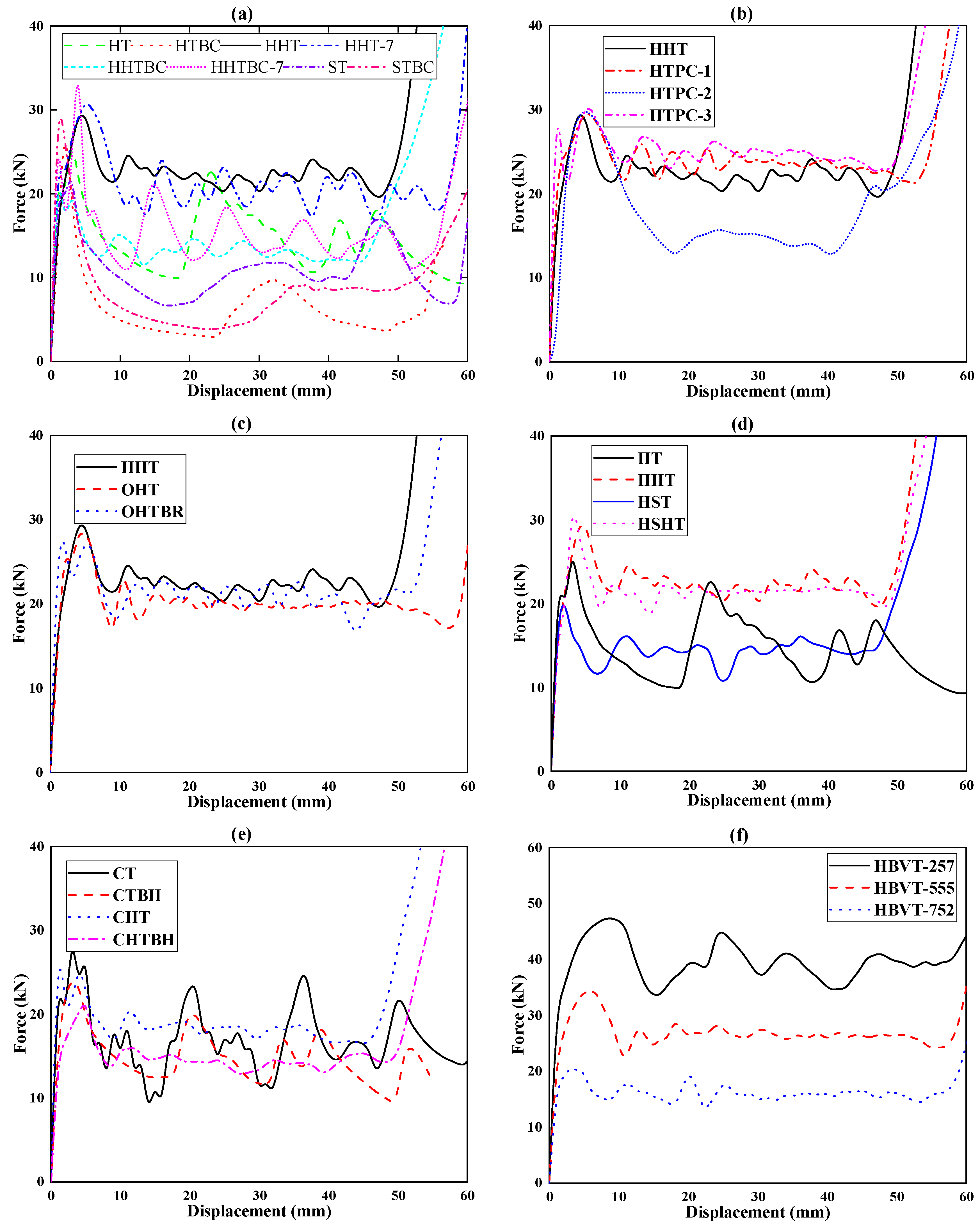
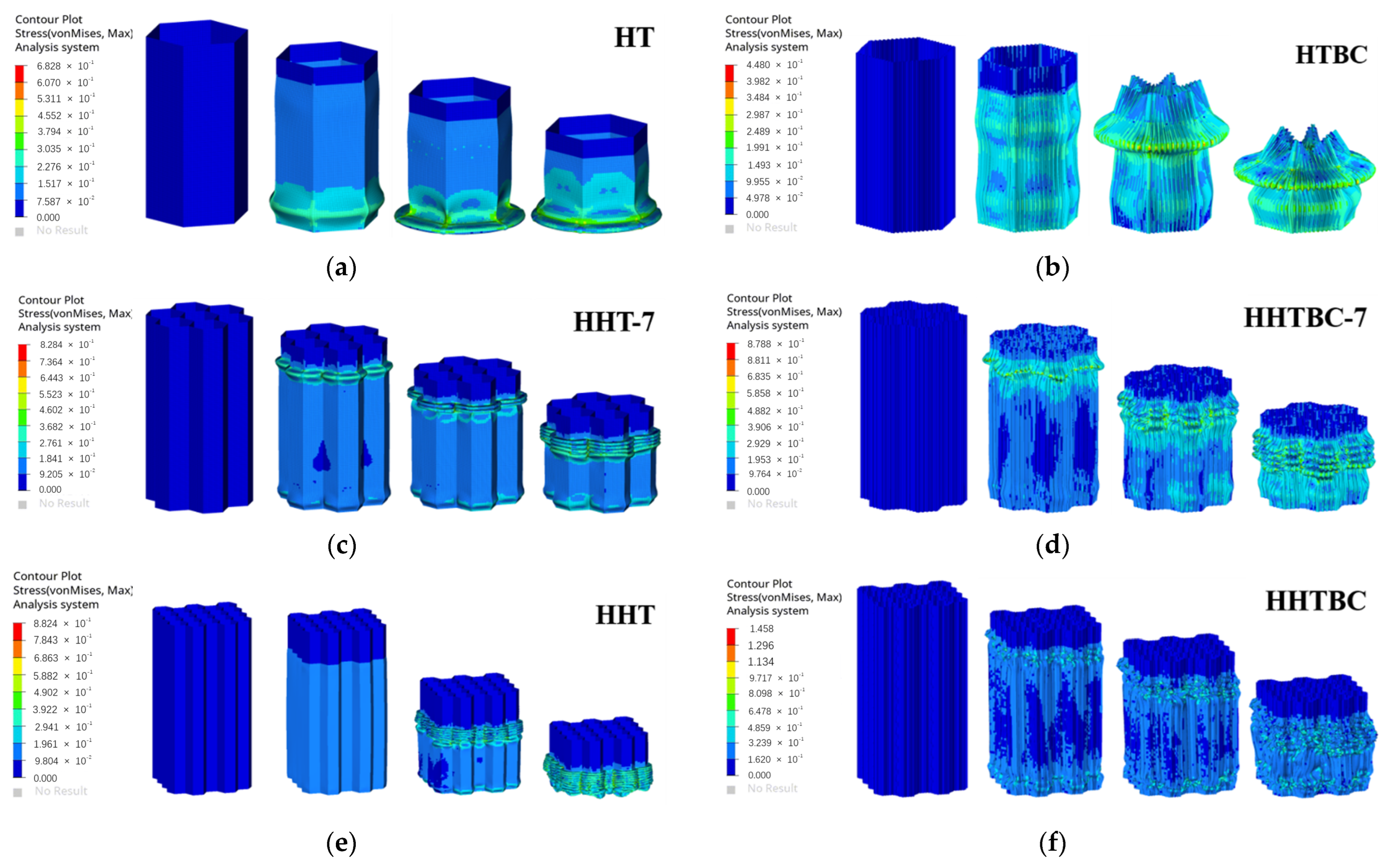
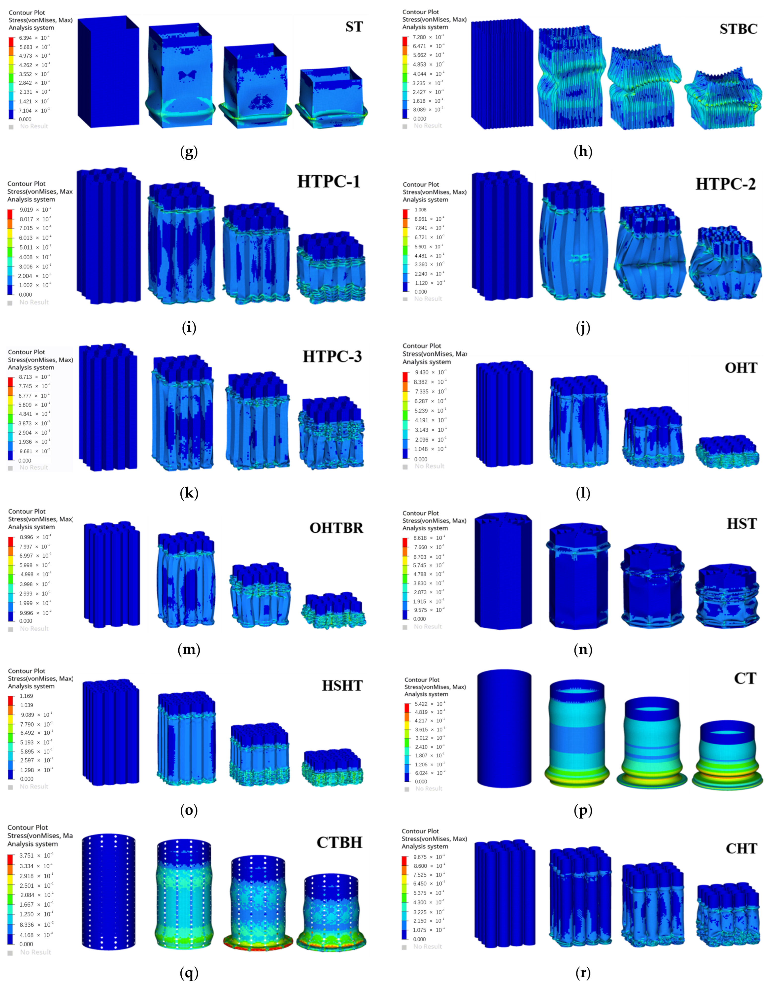
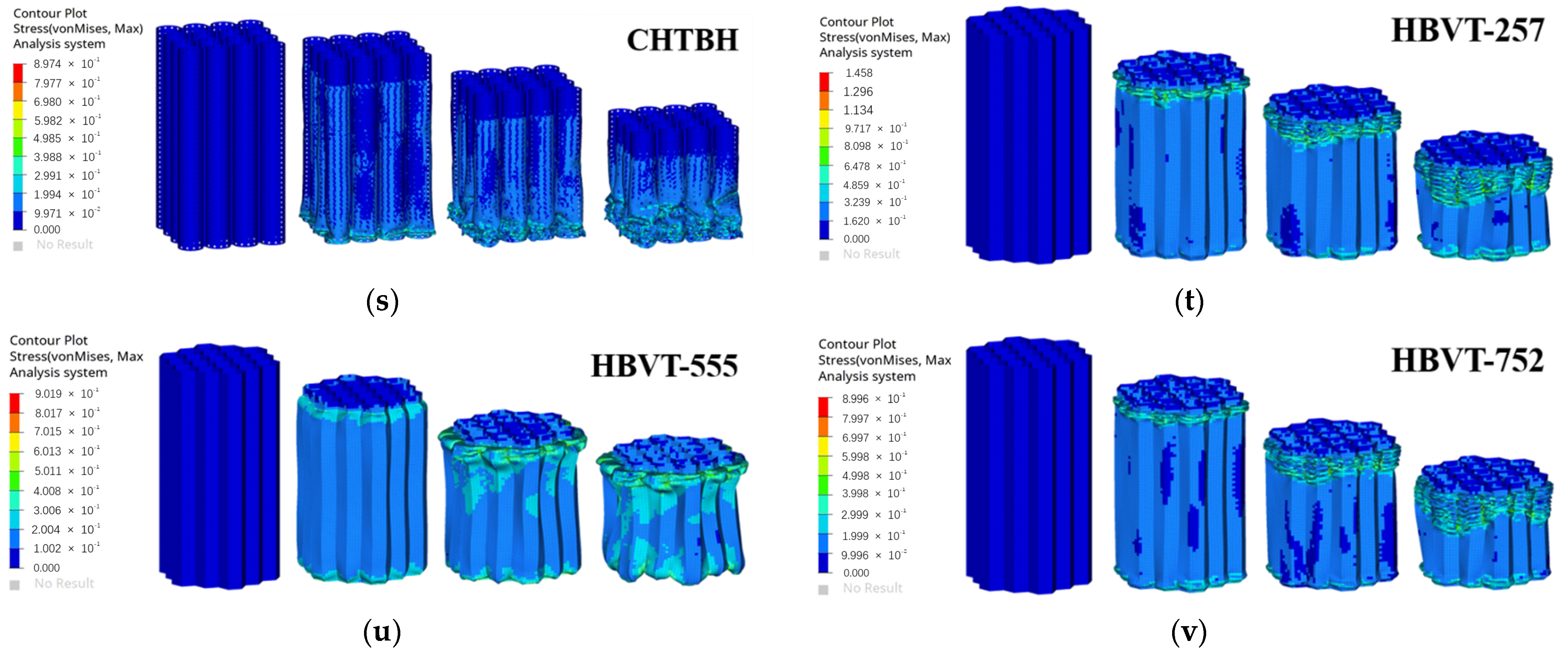
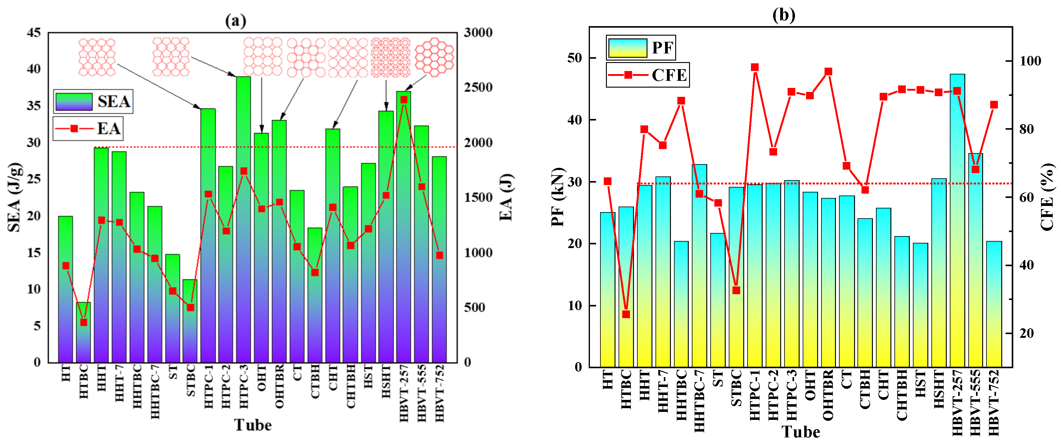
3.3. Results and Analysis
4. Experimental Study
4.1. Processing and Manufacturing
4.2. Results and Analysis
5. Conclusions
Author Contributions
Funding
Data Availability Statement
Conflicts of Interest
References
- Xiang, X.; Zou, S.; San Ha, N.; Lu, G. Energy absorption of bio-inspired multi-layered graded foam-filled structures under axial crushing. Compos. Part B Eng. 2020, 198, 108216. [Google Scholar] [CrossRef]
- San Ha, N.; Lu, G.; Shu, D.; Yu, T.X. Mechanical properties and energy absorption characteristics of tropical fruit durian (Durio zibethinus). J. Mech. Behav. Biomed. Mater. 2020, 104, 103603. [Google Scholar]
- Nian, Y.; Wan, S.; Li, X.; Su, Q.; Li, M. How does bio-inspired graded honeycomb filler affect energy absorption characteristics. Thin-Walled Struct. 2019, 144, 106269. [Google Scholar] [CrossRef]
- Lu, Q.; Qi, D.; Li, Y.; Xiao, D.; Wu, W. Impact energy absorption performances of ordinary and hierarchical chiral structures. Thin-Walled Struct. 2019, 140, 495–505. [Google Scholar] [CrossRef]
- Liu, Q.; Mo, Z.; Wu, Y.; Ma, J.; Tsui, G.C.P.; Hui, D. Crush response of CFRP square tube filled with aluminum honeycomb. Compos. Part B Eng. 2016, 98, 406–414. [Google Scholar] [CrossRef]
- Jiang, W.; Ma, H.; Wang, J.; Feng, M.; Qu, S. Mechanical metamaterial with negative Poisson’s ratio based on circular honeycomb core. Chin. Sci. Bull. 2016, 61, 1421–1427. [Google Scholar] [CrossRef]
- Han, B.; Qin, K.; Yu, B.; Wang, B.; Zhang, Q.; Lu, T.J. Honeycomb–corrugation hybrid as a novel sandwich core for significantly enhanced compressive performance. Mater. Des. 2016, 93, 271–282. [Google Scholar] [CrossRef]
- Fischer, S.F.; Thielen, M.; Loprang, R.R.; Seidel, R.; Fleck, C.; Speck, T.; Bührig-Polaczek, A. Pummelos as concept generators for biomimetically inspired low weight structures with excellent damping properties. Adv. Eng. Mater. 2010, 12, 658–663. [Google Scholar] [CrossRef]
- Seidel, R.; Thielen, M.; Schmitt, C.; Bührig-Polaczek, A.; Fleck, C.; Speck, T. Fruit walls and nut shells as an inspiration for the design of bio-inspired impact resistant hierarchically structured materials. Des. Nat. 2010, V, 421–430. [Google Scholar]
- Bührig-Polaczek, A.; Fleck, C.; Speck, T.; Schüler, P.; Fischer, S.F.; Caliaro, M.; Thielen, M. Biomimetic cellular metals—Using hierarchical structuring for energy absorption. Bioinspiration Biomim. 2016, 11, 045002. [Google Scholar] [CrossRef]
- Ha, N.S.; Le, V.T.; Goo, N.S. Investigation of punch resistance of the Allomyrira dichtoloma beetle forewing. J. Bionics. Eng. 2018, 15, 57–68. [Google Scholar] [CrossRef]
- Kitchener, A. An analysis of the forces of fighting of the blackbuck (Antilope cervicapra) and the bighorn sheep (Ovis canadensis) and the mechanical design of the horn of bovids. J. Zool. 1988, 214, 1–20. [Google Scholar] [CrossRef]
- Li, B.-W.; Zhao, H.-P.; Feng, X.-Q. Static and dynamic mechanical properties of cattle horns. Mater. Sci. Eng. C 2011, 31, 179–183. [Google Scholar] [CrossRef]
- McKittrick, J.; Chen, P.Y.; Tombolato, L.; Novitskaya, E.E.; Trim, M.W.; Hirata, G.A.; Olevsky, E.A.; Horstemeyer, M.F.; Meyers, M.A. Energy absorbent natural materials and bioinspired design strategies: A review. Mater. Sci. Eng. C 2010, 30, 331–342. [Google Scholar] [CrossRef]
- San Ha, N.; Lu, G. A review of recent research on bio-inspired structures and materials for energy. Compos. Part B Eng. 2020, 181, 107496. [Google Scholar]
- Lin, K.; Gu, D.; Hu, K.; Yang, J.; Wang, H.; Yuan, L.; Shi, X.; Meng, L. Laser powder bed fusion of bio-inspired honeycomb structures: Effect of twist angle on compressive behaviors. Thin-Walled Struct. 2021, 159, 107252. [Google Scholar] [CrossRef]
- Zhang, X.C.; An, C.C.; Shen, Z.F.; Wu, H.X.; Yang, W.G.; Bai, J.P. Dynamic crushing responses of bio-inspired re-entrant auxetic honeycombs under in-plane impact loading. Mater. Today Commun. 2020, 23, 100918. [Google Scholar] [CrossRef]
- Jiang, H.; Ren, Y.; Jin, Q.; Zhu, G.; Hu, Y.; Cheng, F. Crashworthiness of novel concentric auxetic reentrant honeycomb with negative Poisson’s ratio biologically inspired by coconut palm. Thin-Walled Struct. 2020, 154, 106911. [Google Scholar] [CrossRef]
- Zhang, W.; Yin, S.; Yu, T.X.; Xu, J. Crushing resistance and energy absorption of pomelo peel inspired hierarchical honeycomb. Int. J. Impact Eng. 2019, 125, 163–172. [Google Scholar] [CrossRef]
- Hu, D.; Wang, Y.; Song, B.; Dang, L.; Zhang, Z. Energy-absorption characteristics of a bionic honeycomb tubular nested structure inspired by bamboo under axial crushing. Compos. Part B Eng. 2019, 162, 21–32. [Google Scholar] [CrossRef]
- Song, J.; Xu, S.; Liu, S.; Zou, M. Study on the crashworthiness of bio-inspired multi-cell tube under axial impact. Int. J. Crashworthiness 2020, 27, 390–399. [Google Scholar] [CrossRef]
- Chen, J.; Zhang, X.; Okabe, Y.; Xie, J.; Xu, M. Beetle elytron plate and the synergistic mechanism of a trabecular-honeycomb core structure. Sci. China Technol. Sci. 2019, 62, 87–93. [Google Scholar] [CrossRef]
- Du, J.; Hao, P. Investigation on Microstructure of Beetle Elytra and Energy Absorption Properties of Bio-Inspired Honeycomb Thin-Walled Structure under Axial Dynamic Crushing. Nanomaterials 2018, 8, 667. [Google Scholar] [CrossRef] [PubMed]
- Yang, X.; Sun, Y.; Yang, J.; Pan, Q. Out-of-plane crashworthiness analysis of bio-inspired aluminum honeycomb patterned with horseshoe mesostructure. Thin-Walled Struct. 2018, 125, 1–11. [Google Scholar] [CrossRef]
- Wu, Y.; Liu, Q.; Fu, J.; Li, Q.; Hui, D. Dynamic crash responses of bio-inspired aluminium honeycomb sandwich structure with CFRP panels. Compos. Part B 2017, 121, 122–133. [Google Scholar] [CrossRef]
- Xiang, J.; Du, J. Energy absorption characteristics of bio-inspired honeycomb structure under axial impact loading. Mater. Sci. Eng. A 2017, 696, 283–289. [Google Scholar] [CrossRef]
- Zhou, J.; Liu, S.; Guo, Z.; Xu, S.; Song, J.; Zou, M. Study on the energy absorption performance of bionic tube inspired by yak horn. Mech. Adv. Mater. Struct. 2021, 29, 7246–7258. [Google Scholar] [CrossRef]
- Fuller, L.H.; Donahue, S.W. Material properties of bighorn sheep (Ovis canadensis) horncore bone with implications for energy absorption during impacts. J. Mech. Behav. Biomed. Mater. 2021, 114, 104224. [Google Scholar] [CrossRef]
- Igathinathane, C.; Womac, A.R.; Sokhansanj, S. Corn stalk orientation effect on mechanical cutting. Biosyst. Eng. 2010, 107, 97–106. [Google Scholar] [CrossRef]
- Al-Zube, L.; Sun, W.; Robertson, D.; Cook, D. The elastic modulus for maize stems. Plant Methods 2018, 11, 14. [Google Scholar] [CrossRef]
- Mengxiang, G.; Kangquan, G.; Zhongping, Y.; Xingshu, L. Study on Mechanical Properties of Cornstalk. Trans. Chin. Soc. Agric. Mach. 2003, 34, 47–49. [Google Scholar]
- Robertson, D.J.; Julias, M.; Gardunia, B.W.; Barten, T.; Cook, D.D. Corn Stalk Lodging: A Forensic Engineering Approach Provides Insights into Failure Patterns and Mechanisms. Crop Sci. 2015, 55, 2833. [Google Scholar] [CrossRef]
- Shah, D.U.; Reynolds, T.P.; Ramage, M.H. The strength of plants: Theory and experimental methods to measure the mechanical properties of stems. J. Exp. Bot. 2017, 68, 4497–4516. [Google Scholar] [CrossRef] [PubMed]
- Vinayagar, K.; Kumar, A.S. Crashworthiness analysis of double section bi-tubular thin-walled structures. Thin-Walled Struct. 2017, 112, 184–193. [Google Scholar] [CrossRef]
- Han, G.; Umemura, K.; Kawai, S.; Kajita, H. Improvement mechanism of bondability in UF-bonded reed and wheat straw boards by silane coupling agent and extraction treatments. J. Wood Sci. 1999, 45, 299–305. [Google Scholar] [CrossRef]
- Sun, Z.Y.; Liang, H.X. Study on core separation and comprehensive utilization of corn stover. Agric. Pastor. Prod. Dev. 1999, 5, 17–18. [Google Scholar]
- Chen, C.K.; Li, F.D.; Yan, Y.F. Experimental study on mechanical properties of sorghum straw. J. Chin. Agric. Mech. 2016, 37, 130–135. [Google Scholar]
- Yeonju, N.; Min-Su, L.; Umer, M.C.; Tea-Sung, J. Effect of strain rate on the deformation of 6061-T6 aluminum alloy at cryogenic temperature. Mater. Charact. 2023, 206, 113403. [Google Scholar]
- Manes, A.; Peroni, L.; Scapin, M.; Giglio, M. Analysis of strain rate behavior of an Al 6061 T6 alloy. Procedia Eng. 2011, 10, 3477–3482. [Google Scholar] [CrossRef]
- Jahromi, A.G.; Hatami, H. Energy absorption performance on multilayer expanded metal tubes under axial impact. Thin-Walled Struct. 2017, 116, 1–11. [Google Scholar] [CrossRef]
- Mohammadiha, O.; Beheshti, H.; Aboutalebi, F.H. Multi-objective optimisation of functionally graded honeycomb filled crash boxes under oblique impact loading. Int. J. Crashworthiness 2014, 20, 44–59. [Google Scholar] [CrossRef]
- Xu, P.; Xing, J.; Yao, S.; Yang, C.; Chen, K.; Li, B. Energy distribution analysis and multi-objective optimization of a gradual energy-absorbing structure for subway vehicles. Thin-Walled Struct. 2017, 115, 255–263. [Google Scholar] [CrossRef]
- Reuter, C.; TRÖSTER, T. Crashworthiness and numerical simulation of hybrid aluminium-CFRP tubes under axial impact. Thin-Walled Struct. 2017, 117, 1–9. [Google Scholar] [CrossRef]
- Song, J.; Xu, S.; Zhou, J.; Huang, H.; Zou, M. Experiment and numerical simulation study on the bionic tubes with gradient thickness under oblique loading. Thin-Walled Struct. 2021, 163, 107624. [Google Scholar] [CrossRef]
- Song, J.F.; Xu, S.C.; Wang, H.X.; Wu, X.Q.; Zou, M. Bionic design and multi-objective optimization for variable wall thickness tube inspired bamboo structures. Thin-Walled Struct. 2018, 125, 76–88. [Google Scholar] [CrossRef]
- Jiapeng, S.; Yulong, H.E.; Xiujuan, Z.; Xin, L.; Minghui, L.; Yanfeng, C. Energy absorption and topology optimization of self-similar inspired multi-cell square tubes. Thin-Walled Struct. 2024, 196, 111491. [Google Scholar]
- Jundong, Z.; Ruiyao, L.; Xiang, L.; Qing, C.; Zhiying, W.; Yunting, G.; Zhixin, L.; Qi, Z.; Zezhou, X.; Guofeng, Y.; et al. Characteristic analysis of bionic-induced structures with negative stiffness inspired by the growth and deformation differences of branches. Thin-Walled Struct. 2024, 196, 111437. [Google Scholar]


| No. | Sample | Thickness/mm | Mass/g | EA/J | SEA/J/g | Fmax/kN | Fmean/kN | CFE/% |
|---|---|---|---|---|---|---|---|---|
| 1 | HT | 1.52 | 44.26 | 891.25 | 20.14 | 25.06 | 17.825 | 71.13 |
| 2 | HTBC | 0.72 | 44.29 | 364.86 | 8.24 | 25.91 | 7.2972 | 28.16 |
| 3 | HHT-7 | 0.81 | 44.31 | 1274.67 | 28.77 | 30.81 | 25.4934 | 82.74 |
| 4 | HHTBC-7 | 0.61 | 44.40 | 1100.76 | 24.79 | 32.82 | 22.0152 | 67.08 |
| 5 | HHT | 0.51 | 44.28 | 1294.77 | 29.24 | 29.46 | 25.8954 | 87.90 |
| 6 | HHTBC | 0.34 | 44.38 | 1157.32 | 26.08 | 20.16 | 23.1464 | 114.81 |
| 7 | ST | 1.28 | 44.24 | 693.858 | 15.68 | 21.63 | 13.87716 | 64.16 |
| 8 | STBC | 0.82 | 44.25 | 522.401 | 11.81 | 29.09 | 10.44802 | 35.92 |
| 9 | HTPC-1 | 0.45 | 44.27 | 1593.38 | 35.99 | 29.52 | 31.8676 | 107.95 |
| 10 | HTPC-2 | 0.43 | 44.70 | 1196.78 | 26.77 | 29.70 | 23.9356 | 80.59 |
| 11 | HTPC-3 | 0.44 | 44.62 | 1826.39 | 40.93 | 30.13 | 36.5278 | 121.23 |
| 12 | OHT | 0.39 | 44.66 | 1397.5 | 31.29 | 28.30 | 27.95 | 98.76 |
| 13 | OHTBR | 0.45 | 44.15 | 1459.85 | 33.07 | 27.38 | 29.197 | 106.64 |
| 14 | HST | 0.42 | 44.71 | 1215.82 | 27.19 | 20.03 | 24.3164 | 121.40 |
| 15 | HSHT | 1.81 | 44.39 | 1525.74 | 34.28 | 30.56 | 30.5148 | 99.85 |
| 16 | CT | 1.65 | 44.78 | 1053.49 | 23.53 | 27.69 | 21.0698 | 76.09 |
| 17 | CTBH | 1.75 | 44.55 | 820.196 | 18.41 | 24.02 | 16.40392 | 68.29 |
| 18 | CHT | 0.39 | 44.30 | 1411.81 | 31.87 | 25.37 | 28.2362 | 111.30 |
| 19 | CHTBH | 0.43 | 44.41 | 1065.09 | 23.98 | 21.14 | 21.3018 | 100.77 |
| 20 | HBVT-257 | 0.25/0.5/0.75 | 53.73 | 2376.98 | 37.02 | 47.40 | 47.5396 | 100.29 |
| 21 | HBVT-555 | 0.51 | 44.28 | 1294.77 | 29.24 | 34.55 | 25.8954 | 74.95 |
| 22 | HBVT-752 | 0.75/0.5/0.25 | 34.83 | 978.51 | 28.23 | 20.42 | 19.5702 | 95.84 |
| No | Sample | Mass/g | EA/J | SEA/J/g |
|---|---|---|---|---|
| 1 | HBVT-555 | 64 | 1609.60 | 25.15 |
| 2 | HBVT-257 | 75 | 2124.00 | 28.32 |
| 3 | HBVT-752 | 105 | 2573.55 | 24.51 |
| 4 | HTPC-3 | 85 | 2625.65 | 30.89 |
| 5 | OHT | 77 | 1973.51 | 25.63 |
| 6 | OHTBR | 108 | 1995.92 | 27.74 |
| 7 | HSHT | 125 | 3478.75 | 27.83 |
Disclaimer/Publisher’s Note: The statements, opinions and data contained in all publications are solely those of the individual author(s) and contributor(s) and not of MDPI and/or the editor(s). MDPI and/or the editor(s) disclaim responsibility for any injury to people or property resulting from any ideas, methods, instructions or products referred to in the content. |
© 2024 by the authors. Licensee MDPI, Basel, Switzerland. This article is an open access article distributed under the terms and conditions of the Creative Commons Attribution (CC BY) license (https://creativecommons.org/licenses/by/4.0/).
Share and Cite
Xu, S.; Chen, N.; Qin, H.; Zou, M.; Song, J. Biomimetic Study of a Honeycomb Energy Absorption Structure Based on Straw Micro-Porous Structure. Biomimetics 2024, 9, 60. https://doi.org/10.3390/biomimetics9010060
Xu S, Chen N, Qin H, Zou M, Song J. Biomimetic Study of a Honeycomb Energy Absorption Structure Based on Straw Micro-Porous Structure. Biomimetics. 2024; 9(1):60. https://doi.org/10.3390/biomimetics9010060
Chicago/Turabian StyleXu, Shucai, Nuo Chen, Haoyi Qin, Meng Zou, and Jiafeng Song. 2024. "Biomimetic Study of a Honeycomb Energy Absorption Structure Based on Straw Micro-Porous Structure" Biomimetics 9, no. 1: 60. https://doi.org/10.3390/biomimetics9010060
APA StyleXu, S., Chen, N., Qin, H., Zou, M., & Song, J. (2024). Biomimetic Study of a Honeycomb Energy Absorption Structure Based on Straw Micro-Porous Structure. Biomimetics, 9(1), 60. https://doi.org/10.3390/biomimetics9010060