A High Coordination of Cross-Links Is Beneficial for the Strength of Cross-Linked Fibers


Abstract
:
1. Introduction
2. Method
3. Results and Discussion
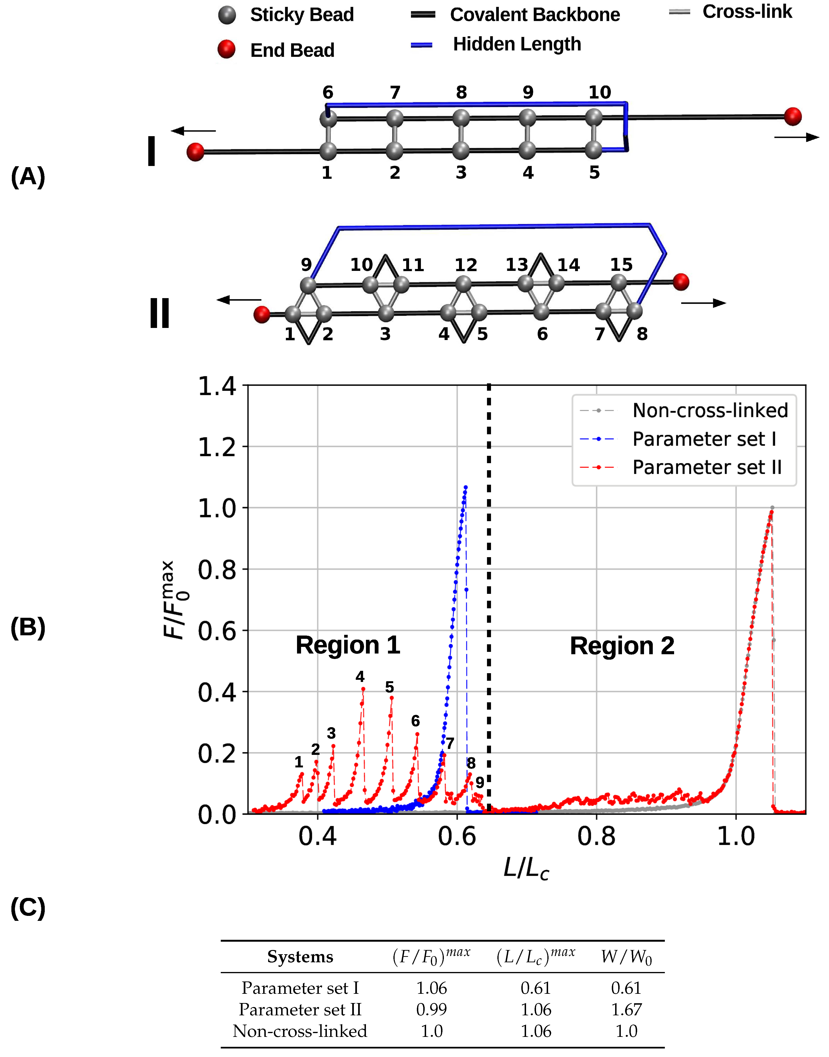
3.1. Single Chain
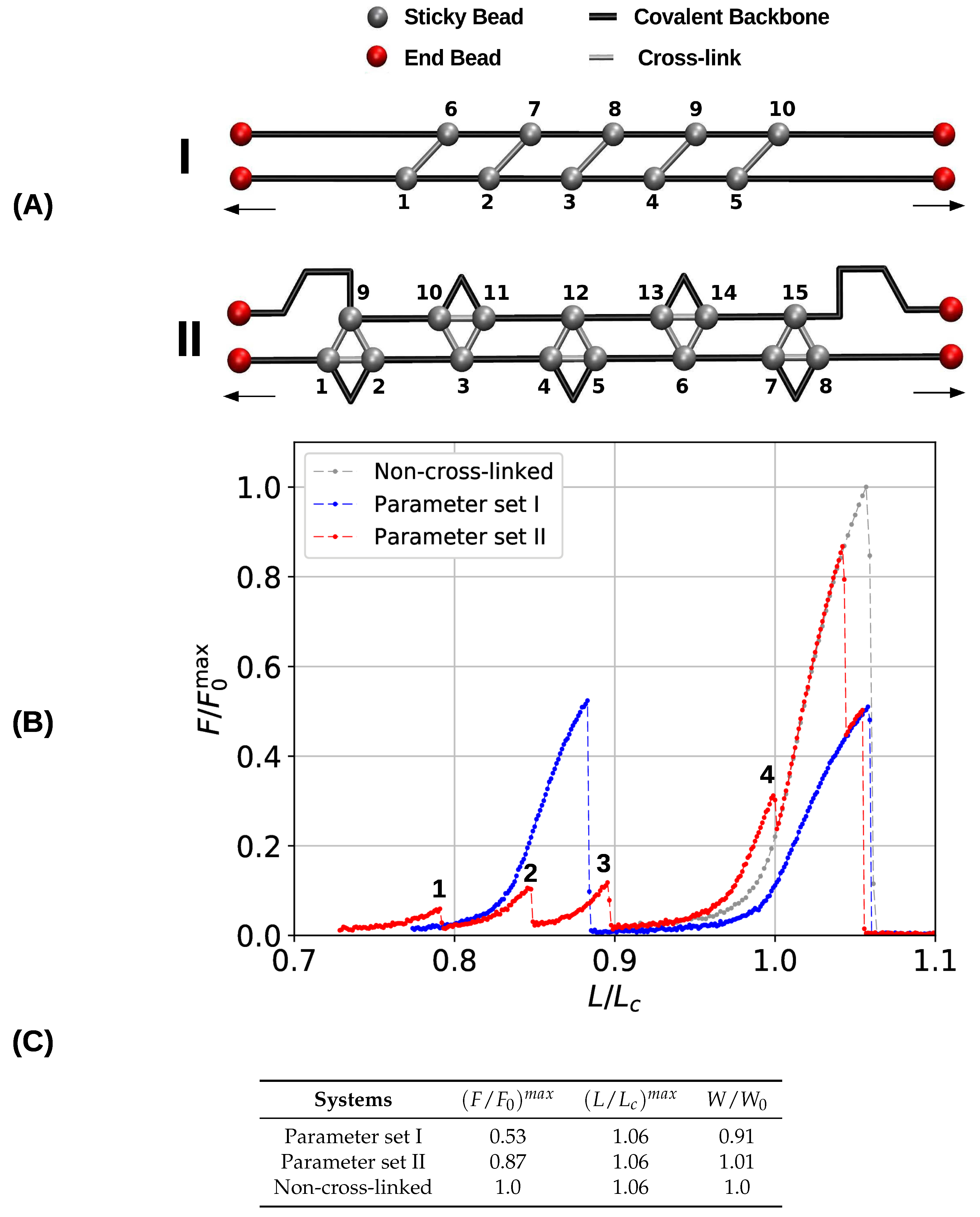
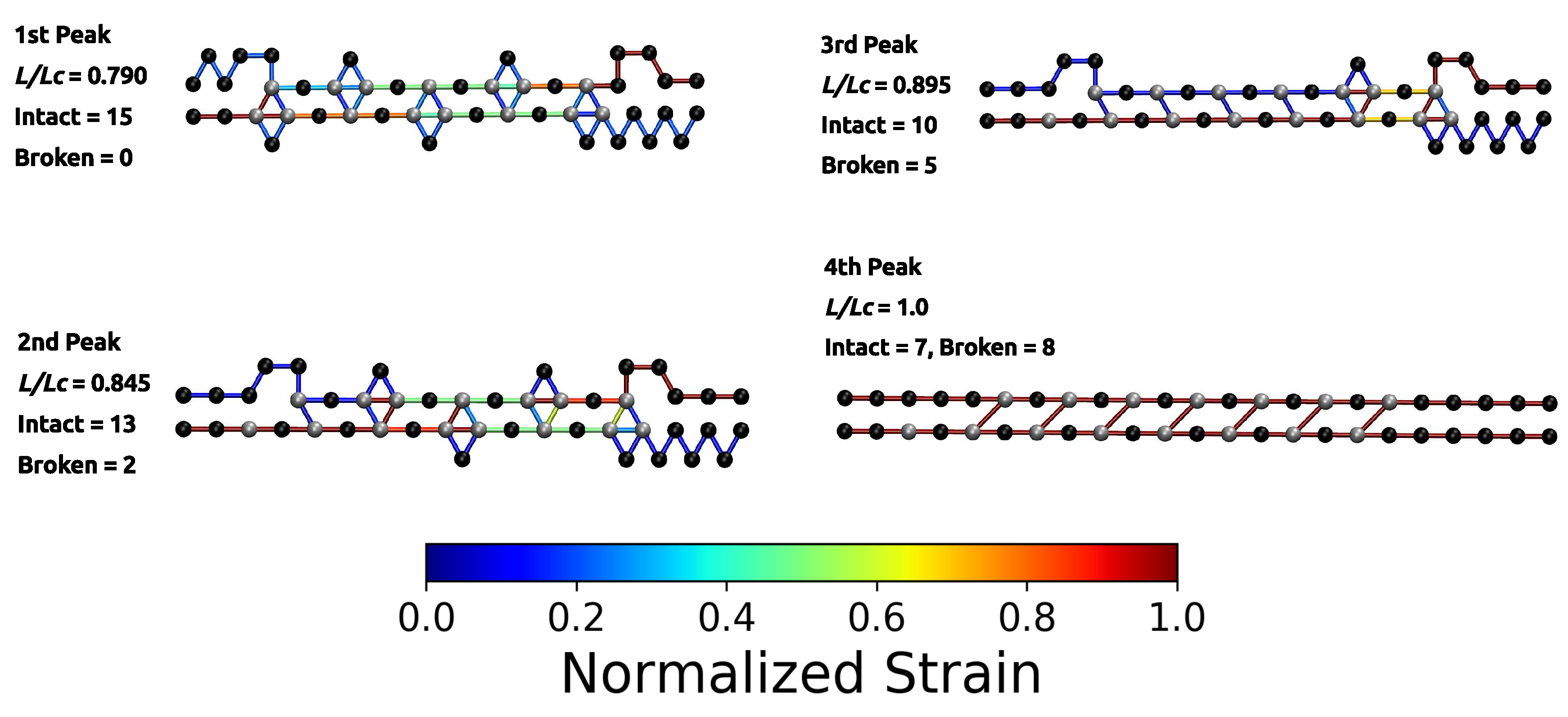
3.2. Two Chain System
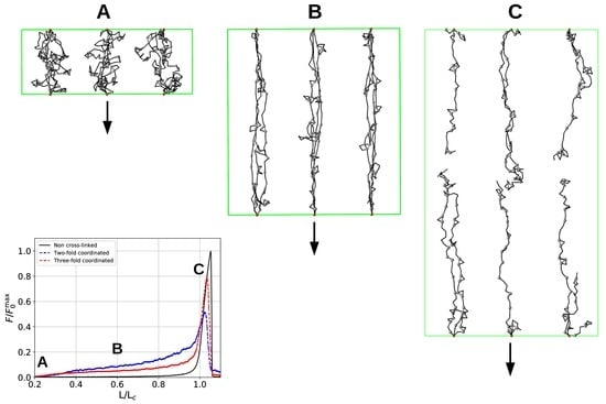
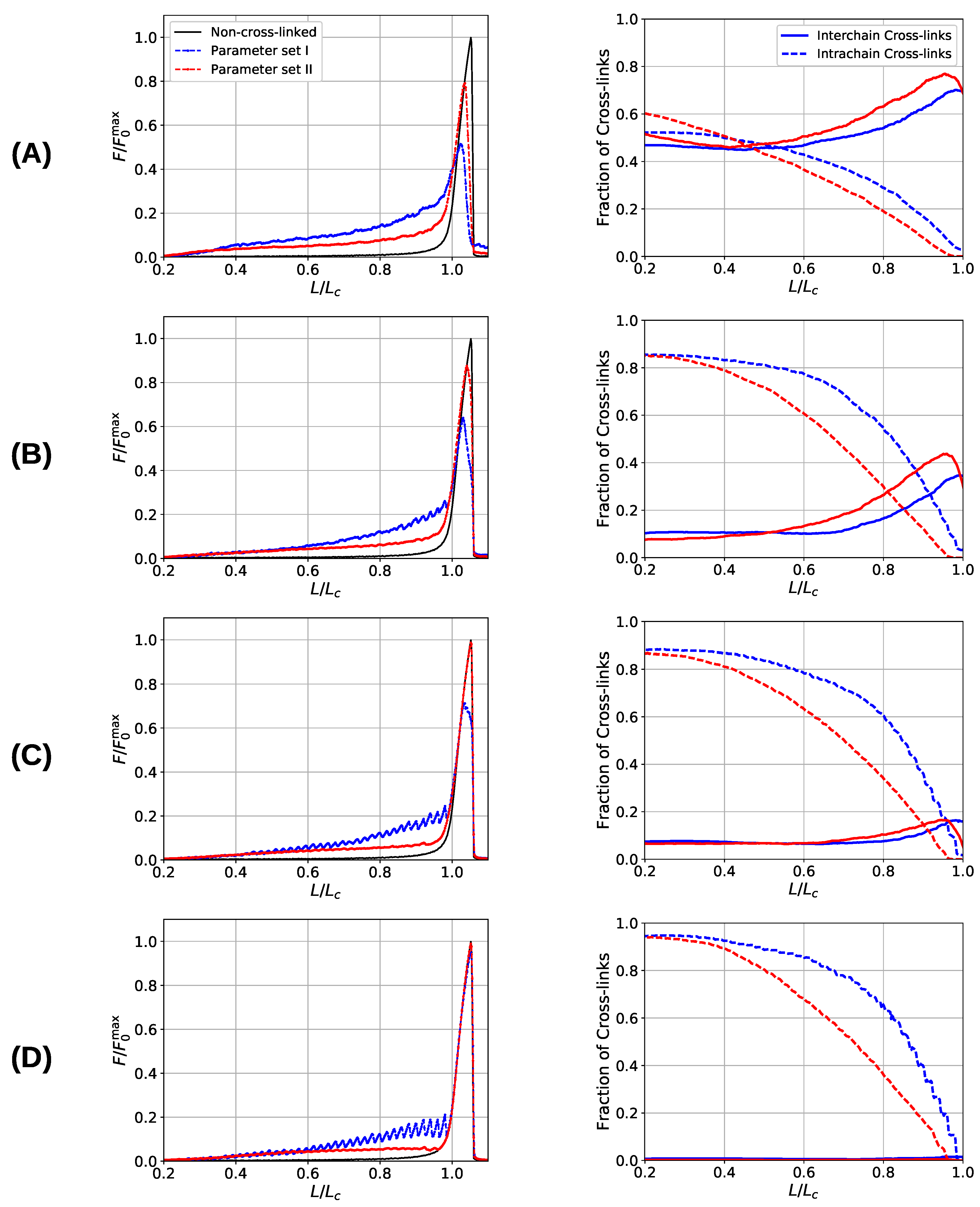
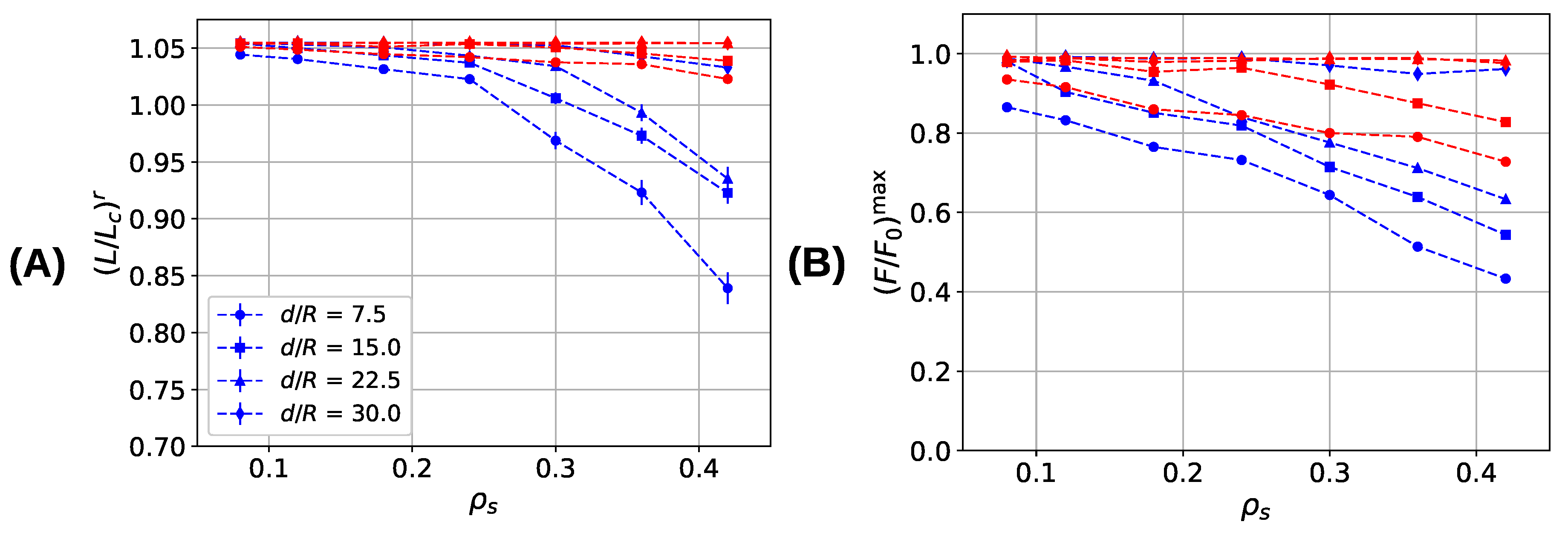
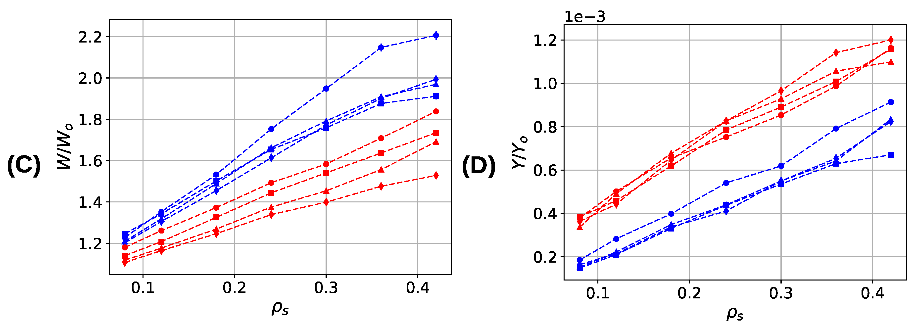
3.3. Aligned Fiber Bundle
4. Conclusions
Author Contributions
Funding
Acknowledgments
Conflicts of Interest
References
- Abe, A.; Dusek, K.; Kobayashi, S. (Eds.) Crosslinking in Materials Science; Advances in Polymer Science Volume 184; Springer: Berlin/Heidelberg, Germany, 2005; ISBN 978-3-540-25831-5. [Google Scholar]
- Carrillo, J.-M.Y.; MacKintosh, F.C.; Dobrynin, A.V. Nonlinear elasticity: From single Chain to networks and gels. Macromolecules 2013, 46, 3679–3692. [Google Scholar] [CrossRef]
- Goldbart, P.M.; Castillo, H.E.; Zippelius, A. Randomly crosslinked macromolecular systems: Vulcanization transition to and properties of the amorphous solid state. Adv. Phys. 1996, 45, 393–468. [Google Scholar] [CrossRef]
- Fantner, G.E.; Oroudjev, E.; Schitter, G.; Golde, L.S.; Thurner, P.; Finch, M.M.; Turner, P.; Gutsmann, T.; Morse, D.E.; Hansma, H.; et al. Sacrificial bonds and fidden length: Unraveling molecular mesostructures in tough materials. Biophys. J. 2006, 90, 1411–1418. [Google Scholar] [CrossRef] [PubMed]
- Smith, B.L.; Schäffer, T.E.; Viani, M.; Thompson, J.B.; Frederick, N.A.; Kindt, J.; Belcher, A.; Stucky, G.D.; Morse, D.E.; Hansma, P.K. Molecular mechanistic origin of the toughness of natural adhesives, fibres and composites. Nature 1999, 399, 761–763. [Google Scholar] [CrossRef]
- Gutsmann, T.; Hassenkam, T.; Cutroni, J.A.; Hansma, P.K. Sacrificial bonds in polymer brushes from rat tail tendon functioning as nanoscale velcro. Biophys. J. 2005, 89, 536–542. [Google Scholar] [CrossRef] [PubMed]
- Harrington, M.J.; Gupta, H.S.; Fratzl, P.; Waite, J.H. Collagen insulated from tensile damage by domains that unfold reversibly: In situ X-ray investigation of mechanical yield and damage repair in the mussel byssus. J. Struct. Biol. 2009, 167, 47–54. [Google Scholar] [CrossRef] [PubMed]
- Harrington, M.J.; Masic, A.; Holten-Andersen, N.; Waite, J.H.; Fratzl, P. Iron-Clad Fibers: A metal-based biological strategy for hard flexible coatings. Science 2010, 328, 216–220. [Google Scholar] [CrossRef] [PubMed]
- Schmitt, C.N.Z.; Politi, Y.; Reinecke, A.; Harrington, M.J. Role of sacrificial protein–metal bond exchange in mussel byssal thread self-healing. Biomacromolecules 2015, 16, 2852–2861. [Google Scholar] [CrossRef] [PubMed]
- Fantner, G.E.; Hassenkam, T.; Kindt, J.H.; Weaver, J.C.; Birkedal, H.; Pechenik, L.; Cutroni, J.A.; Cidade, G.A.G.; Stucky, G.D.; Morse, D.E.; et al. Sacrificial bonds and hidden length dissipate energy as mineralized fibrils separate during bone fracture. Nat. Mater. 2005, 4, 612–616. [Google Scholar] [CrossRef] [PubMed]
- Fantner, G.E.; Adams, J.; Turner, P.; Thurner, P.J.; Fisher, L.W.; Hansma, P.K. Nanoscale ion mediated networks in bone: Osteopontin can repeatedly dissipate large amounts of energy. Nano Lett. 2007, 7, 2491–2498. [Google Scholar] [CrossRef] [PubMed]
- Gupta, H.S.; Fratzl, P.; Kerschnitzki, M.; Benecke, G.; Wagermaier, W.; Kirchner, H.O.K. Evidence for an elementary process in bone plasticity with an activation enthalpy of 1 eV. J. R. Soc. Interface 2007, 4, 277–282. [Google Scholar] [CrossRef] [PubMed]
- Keckes, J.; Burgert, I.; Frühmann, K.; Müller, M.; Kölln, K.; Hamilton, M.; Burghammer, M.; Roth, S.V.; Stanzl-Tschegg, S.; Fratzl, P. Cell-wall recovery after irreversible deformation of wood. Nat. Mater. 2003, 2, 810–813. [Google Scholar] [CrossRef] [PubMed]
- Becker, N.; Oroudjev, E.; Mutz, S.; Cleveland, J.P.; Hansma, P.K.; Hayashi, C.Y.; Makarov, D.E.; Hansma, H.G. Molecular nanosprings in spider capture-silk threads. Nat. Mater. 2003, 2, 278–283. [Google Scholar] [CrossRef] [PubMed]
- Ackbarow, T.; Chen, X.; Keten, S.; Buehler, M.J. Hierarchies, multiple energy barriers, and robustness govern the fracture mechanics of α-helical and β-sheet protein domains. Proc. Natl. Acad. Sci. USA 2007, 104, 16410–16415. [Google Scholar] [CrossRef] [PubMed]
- Ashton, N.N.; Stewart, R.J. Self-recovering caddisfly silk: Energy dissipating, Ca+2-dependent, double dynamic network fibers. Soft Matter 2015, 11, 1667–1676. [Google Scholar] [CrossRef] [PubMed]
- Keten, S.; Buehler, M.J. Strength limit of entropic elasticity in beta-sheet protein domains. Phys. Rev. E 2008, 78, 061913. [Google Scholar] [CrossRef] [PubMed]
- Keten, S.; Buehler, M.J. Geometric confinement governs the rupture strength of H-bond assemblies at a critical length scale. Nano Lett. 2008, 8, 743–748. [Google Scholar] [CrossRef] [PubMed]
- Barnes, D.S.; Pettit, L.D. Stereoselectivity in enthalpy changes accompanying the formation of metal complexes of histidine and other amino-acids. J. Inorg. Nucl. Chem. 1971, 33, 2177–2184. [Google Scholar] [CrossRef]
- Xu, Z. Mechanics of metal-catecholate complexes: The roles of coordination state and metal types. Sci. Rep. 2013, 3. [Google Scholar] [CrossRef] [PubMed]
- Wilhelm, J.; Frey, E. Elasticity of stiff polymer networks. Phys. Rev. Lett. 2003, 91, 108103. [Google Scholar] [CrossRef] [PubMed]
- Kierfeld, J.; Kühne, T.; Lipowsky, R. Discontinuous unbinding transitions of filament bundles. Phys. Rev. Lett. 2005, 95, 038102. [Google Scholar] [CrossRef] [PubMed]
- Keten, S.; Xu, Z.; Ihle, B.; Buehler, M.J. Nanoconfinement controls stiffness, strength and mechanical toughness of β-sheet crystals in silk. Nat. Mater. 2010, 9, 359–367. [Google Scholar] [CrossRef] [PubMed]
- Kurniawan, N.A.; Enemark, S.; Rajagopalan, R. The role of structure in the nonlinear mechanics of cross-linked semiflexible polymer networks. J. Chem. Phys. 2012, 136, 065101. [Google Scholar] [CrossRef] [PubMed]
- Benetatos, P.; Ulrich, S.; Zippelius, A. Force–extension relation of cross-linked anisotropic polymer networks. New J. Phys. 2012, 14, 115011. [Google Scholar] [CrossRef]
- Benetatos, P.; von der Heydt, A.; Zippelius, A. Tension-induced binding of semiflexible biopolymers. New J. Phys. 2014, 16, 113037. [Google Scholar] [CrossRef]
- Elbanna, A.E.; Carlson, J.M. Dynamics of polymer molecules with sacrificial bond and hidden length systems: Towards a physically-based mesoscopic constitutive law. PLoS ONE 2013, 8, e56118. [Google Scholar] [CrossRef] [PubMed]
- Lieou, C.K.C.; Elbanna, A.E.; Carlson, J.M. Sacrificial bonds and hidden length in biomaterials: A kinetic constitutive description of strength and toughness in bone. Phys. Rev. E 2013, 88, 012703. [Google Scholar] [CrossRef] [PubMed]
- Nabavi, S.S.; Harrington, M.J.; Fratzl, P.; Hartmann, M.A. Influence of sacrificial bonds on the mechanical behaviour of polymer chains. Bioinspired Biomim. Nanobiomater. 2014, 3, 139–145. [Google Scholar] [CrossRef]
- Reinecke, A.; Bertinetti, L.; Fratzl, P.; Harrington, M.J. Cooperative behavior of a sacrificial bond network and elastic framework in providing self-healing capacity in mussel byssal threads. J. Struct. Biol. 2016, 196, 329–339. [Google Scholar] [CrossRef] [PubMed]
- Degtyar, E.; Harrington, M.J.; Politi, Y.; Fratzl, P. The mechanical role of metal ions in biogenic protein-based materials. Angew. Chem. Int. Ed. 2014, 53, 12026–12044. [Google Scholar] [CrossRef] [PubMed]
- Lee, B.P.; Messersmith, P.B.; Israelachvili, J.N.; Waite, J.H. Mussel-inspired adhesives and coatings. Annu. Rev. Mater. Res. 2011, 41, 99–132. [Google Scholar] [CrossRef] [PubMed]
- Holten-Andersen, N.; Harrington, M.J.; Birkedal, H.; Lee, B.P.; Messersmith, P.B.; Lee, K.Y.C.; Waite, J.H. pH-Induced metal-ligand cross-links inspired by mussel yield self-healing polymer networks with near-covalent elastic moduli. Proc. Natl. Acad. Sci. USA 2011, 108, 2651–2655. [Google Scholar] [CrossRef] [PubMed]
- Barrett, D.G.; Fullenkamp, D.E.; He, L.; Holten-Andersen, N.; Lee, K.Y.C.; Messersmith, P.B. pH-Based regulation of hydrogel mechanical properties through mussel-inspired chemistry and processing. Adv. Funct. Mater. 2013, 23, 1111–1119. [Google Scholar] [CrossRef] [PubMed]
- Depalle, B.; Qin, Z.; Shefelbine, S.J.; Buehler, M.J. Influence of cross-link structure, density and mechanical properties in the mesoscale deformation mechanisms of collagen fibrils. J. Mech. Behav. Biomed. 2015, 52, 1–13. [Google Scholar] [CrossRef] [PubMed]
- Depalle, B.; Duarte, A.G.; Fiedler, I.A.K.; Pujo-Menjouet, L.; Buehler, M.J.; Berteau, J.-P. The different distribution of enzymatic collagen cross-links found in adult and children bone result in different mechanical behavior of collagen. Bone 2018, 110, 107–114. [Google Scholar] [CrossRef] [PubMed]
- Shabbir, H.; Hartmann, M.A. Influence of reversible cross-link coordination on the mechanical behavior of a linear polymer chain. New J. Phys. 2017, 19, 093024. [Google Scholar] [CrossRef]
- Tersoff, J. Empirical interatomic potential for carbon, with applications to amorphous carbon. Phys. Rev. Lett. 1988, 61, 2879–2882. [Google Scholar] [CrossRef] [PubMed]
- Tersoff, J. New empirical approach for the structure and energy of covalent systems. Phys. Rev. B 1988, 37, 6991–7000. [Google Scholar] [CrossRef]
- Nabavi, S.S.; Hartmann, M.A. Weak reversible cross links may decrease the strength of aligned fiber bundles. Soft Matter 2016, 12, 2047–2055. [Google Scholar] [CrossRef] [PubMed]
- Nechay, M.R.; Valdez, C.E.; Alexandrova, A.N. Computational treatment of metalloproteins. J. Phys. Chem. B 2015, 119, 5945–5956. [Google Scholar] [CrossRef] [PubMed]
- Valdez, C.E.; Morgenstern, A.; Eberhart, M.E.; Alexandrova, A.N. Predictive methods for computational metalloenzyme redesign—A test case with carboxypeptidase A. Phys. Chem. 2016, 18, 31744–31756. [Google Scholar] [CrossRef] [PubMed]
- Harrington, M.J.; Waite, J.H. Holdfast heroics: Comparing the molecular and mechanical properties of Mytilus californianus byssal threads. J. Exp. Biol. 2007, 210, 4307–4318. [Google Scholar] [CrossRef] [PubMed]
- Mian, S.A.; Saha, L.C.; Jang, J.; Wang, L.; Gao, X.; Nagase, S. Density functional theory study of catechol adhesion on silica surfaces. J. Phys. Chem. C 2010, 114, 20793–20800. [Google Scholar] [CrossRef]
- Mian, S.A.; Yang, L.-M.; Saha, L.C.; Ahmed, E.; Ajmal, M.; Ganz, E. A fundamental understanding of catechol and water adsorption on a hydrophilic silica surface: Exploring the underwater adhesion mechanism of mussels on an atomic scale. Langmuir 2014, 30, 6906–6914. [Google Scholar] [CrossRef] [PubMed]
- Landau, D.P.; Binder, K. A Guide to Monte Carlo Simulations in Statistical Physics, 3rd ed.; Cambridge University Press: Cambridge, UK, 2014; p. 489. [Google Scholar]
- Eom, K.; Li, P.-C.; Makarov, D.E.; Rodin, G.J. Relationship between the mechanical properties and topology of cross-linked polymer molecules: Parallel strands maximize the strength of model polymers and protein domains. J. Phys. Chem. B 2003, 107, 8730–8733. [Google Scholar] [CrossRef]
- Erickson, H.P. Stretching single protein molecules: Titin is a weird spring. Science 1997, 276, 1090–1092. [Google Scholar] [CrossRef] [PubMed]
- Nabavi, S.S.; Harrington, M.J.; Paris, O.; Fratzl, P.; Hartmann, M.A. The role of topology and thermal backbone fluctuations on sacrificial bond efficacy in mechanical metalloproteins. New J. Phys. 2014, 16, 013003. [Google Scholar] [CrossRef]
- Nabavi, S.S.; Fratzl, P.; Hartmann, M.A. Energy dissipation and recovery in a simple model with reversible cross-links. Phys. Rev. E 2015, 91, 032603. [Google Scholar] [CrossRef] [PubMed]
- Hartmann, M.A.; Fratzl, P. Sacrificial ionic bonds need to be randomly distributed to provide shear deformability. Nano Lett. 2009, 9, 3603–3607. [Google Scholar] [CrossRef] [PubMed]
- Liu, J.; Wang, S.; Tang, Z.; Huang, J.; Guo, B.; Huang, G. Bioinspired engineering of two different types of sacrificial bonds into chemically cross-linked cis-1,4-polyisoprene toward a high-performance elastomer. Macromolecules 2016, 49, 8593–8604. [Google Scholar] [CrossRef]


| Covalent Bonds | Cross-Links | Parameter Set I (Dimers only) | Parameter Set II (Trimers and Dimers) | |
|---|---|---|---|---|
| 200.0 | A | 1,101,324 | 367,108 | |
| R | - | B | 14,840 | 5,396 |
| 3.0 | 3.33 | 3.33 | ||
| 2.0 | 1.66 | 1.66 | ||
| n | 0 | 4 | ||
| - | 1.0 | |||
| - | 0.5 | |||
| c | - | 8.0 | ||
| d | - | 2.0 | ||
| 4.2 | 4.2 | |||
| 1.2 | 1.2 |
© 2019 by the authors. Licensee MDPI, Basel, Switzerland. This article is an open access article distributed under the terms and conditions of the Creative Commons Attribution (CC BY) license (http://creativecommons.org/licenses/by/4.0/).
Share and Cite
Shabbir, H.; Dellago, C.; Hartmann, M.A. A High Coordination of Cross-Links Is Beneficial for the Strength of Cross-Linked Fibers. Biomimetics 2019, 4, 12. https://doi.org/10.3390/biomimetics4010012
Shabbir H, Dellago C, Hartmann MA. A High Coordination of Cross-Links Is Beneficial for the Strength of Cross-Linked Fibers. Biomimetics. 2019; 4(1):12. https://doi.org/10.3390/biomimetics4010012
Chicago/Turabian StyleShabbir, Huzaifa, Christoph Dellago, and Markus A. Hartmann. 2019. "A High Coordination of Cross-Links Is Beneficial for the Strength of Cross-Linked Fibers" Biomimetics 4, no. 1: 12. https://doi.org/10.3390/biomimetics4010012
APA StyleShabbir, H., Dellago, C., & Hartmann, M. A. (2019). A High Coordination of Cross-Links Is Beneficial for the Strength of Cross-Linked Fibers. Biomimetics, 4(1), 12. https://doi.org/10.3390/biomimetics4010012