
Development of 4D-Printed Arterial Stents Utilizing Bioinspired Architected Auxetic Materials

 ,
, 
 ,
,  and
and 
Abstract
1. Introduction
2. Materials and Methods
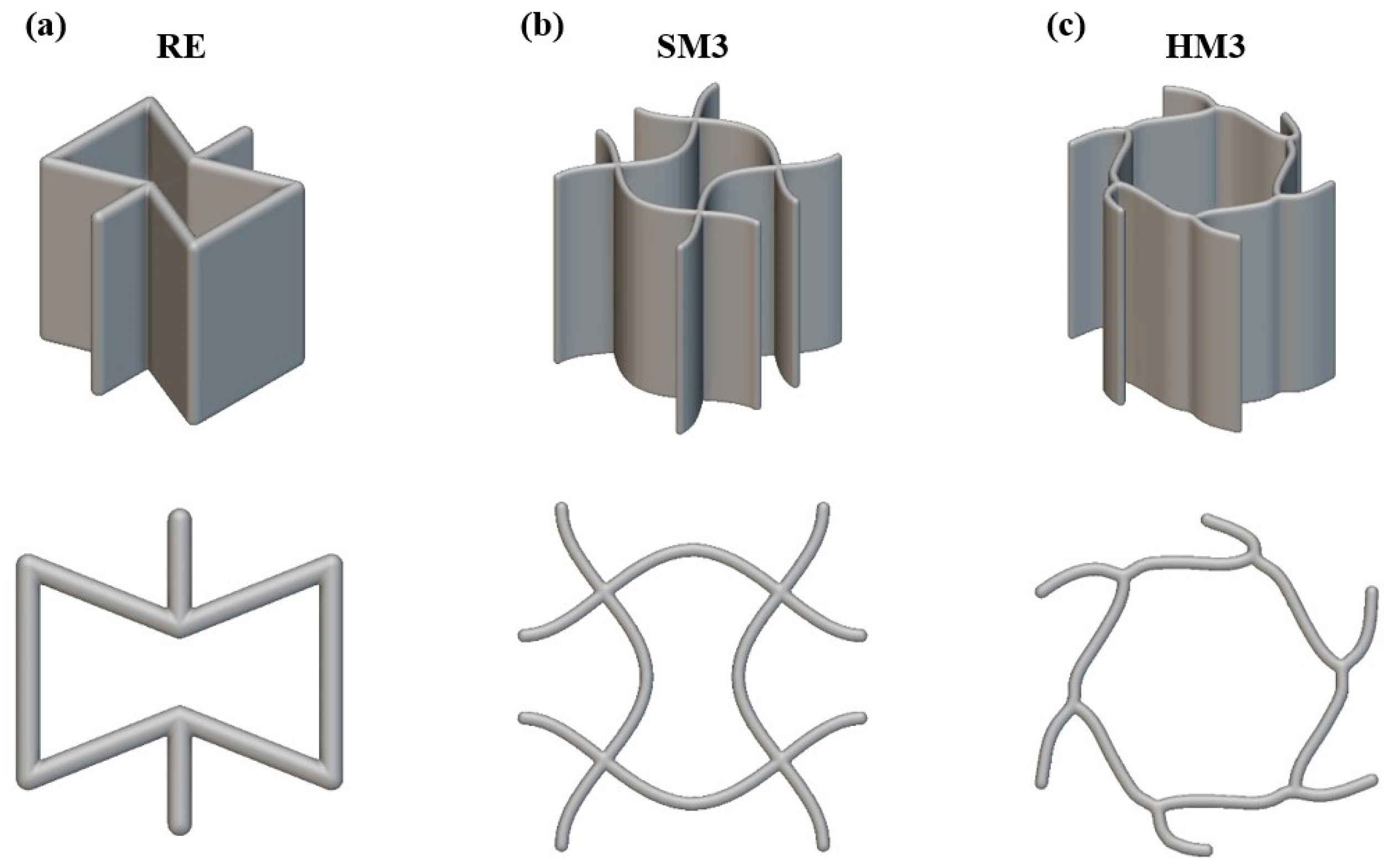
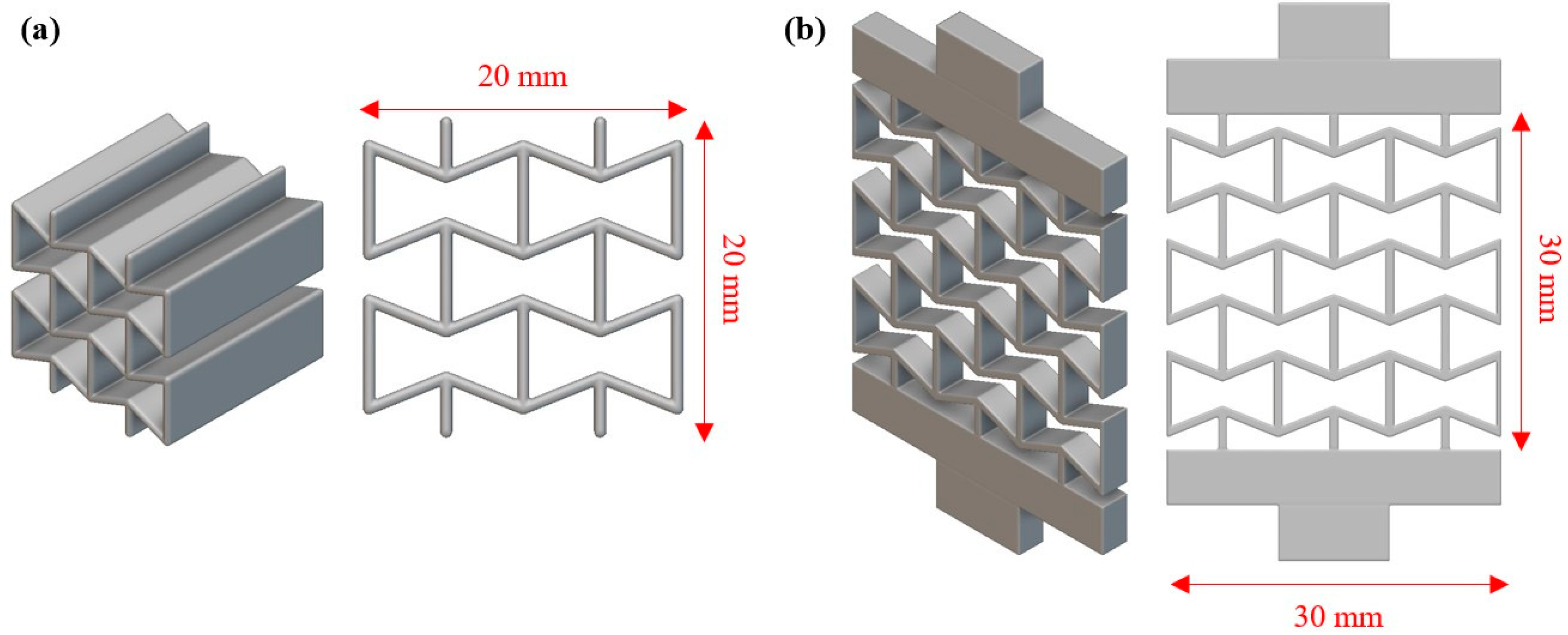
2.1. Design of Auxetic Materials and Arterial Stent
2.2. Additive Manufacturing
2.3. Mechanical Testing
2.4. Finite Element Model
3. Results
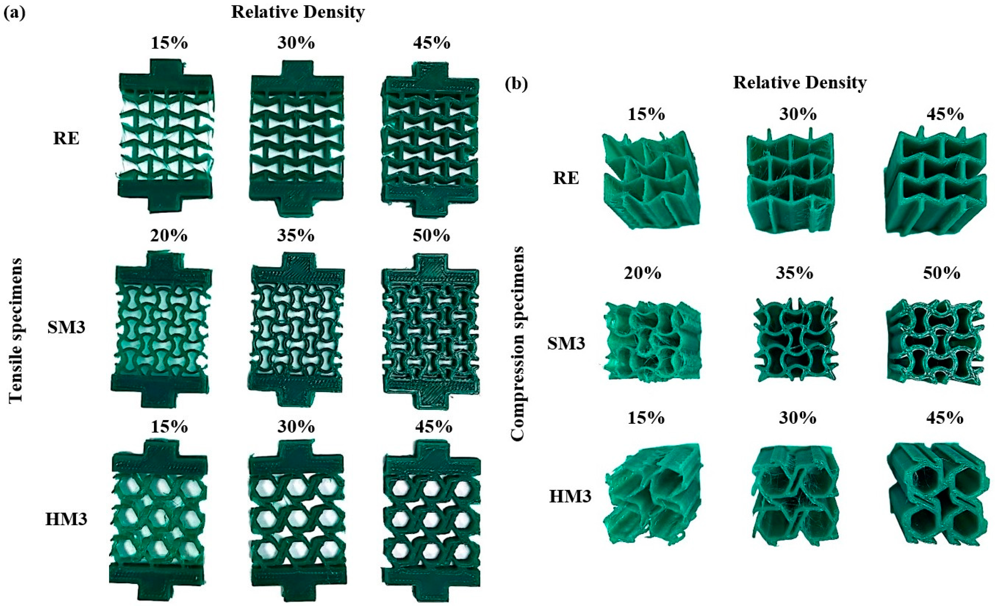
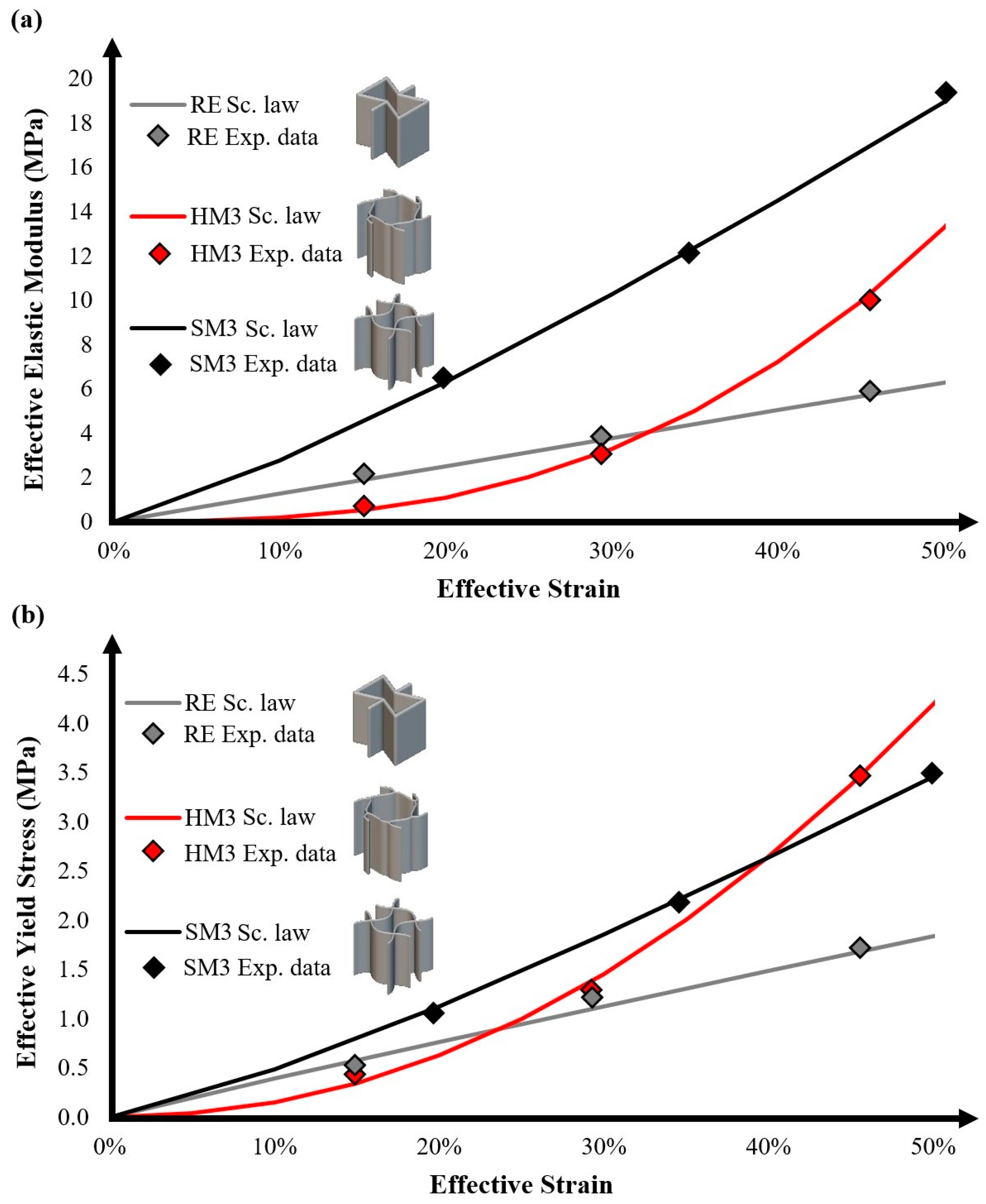
3.1. Fabrication and Mechanical Testing Results
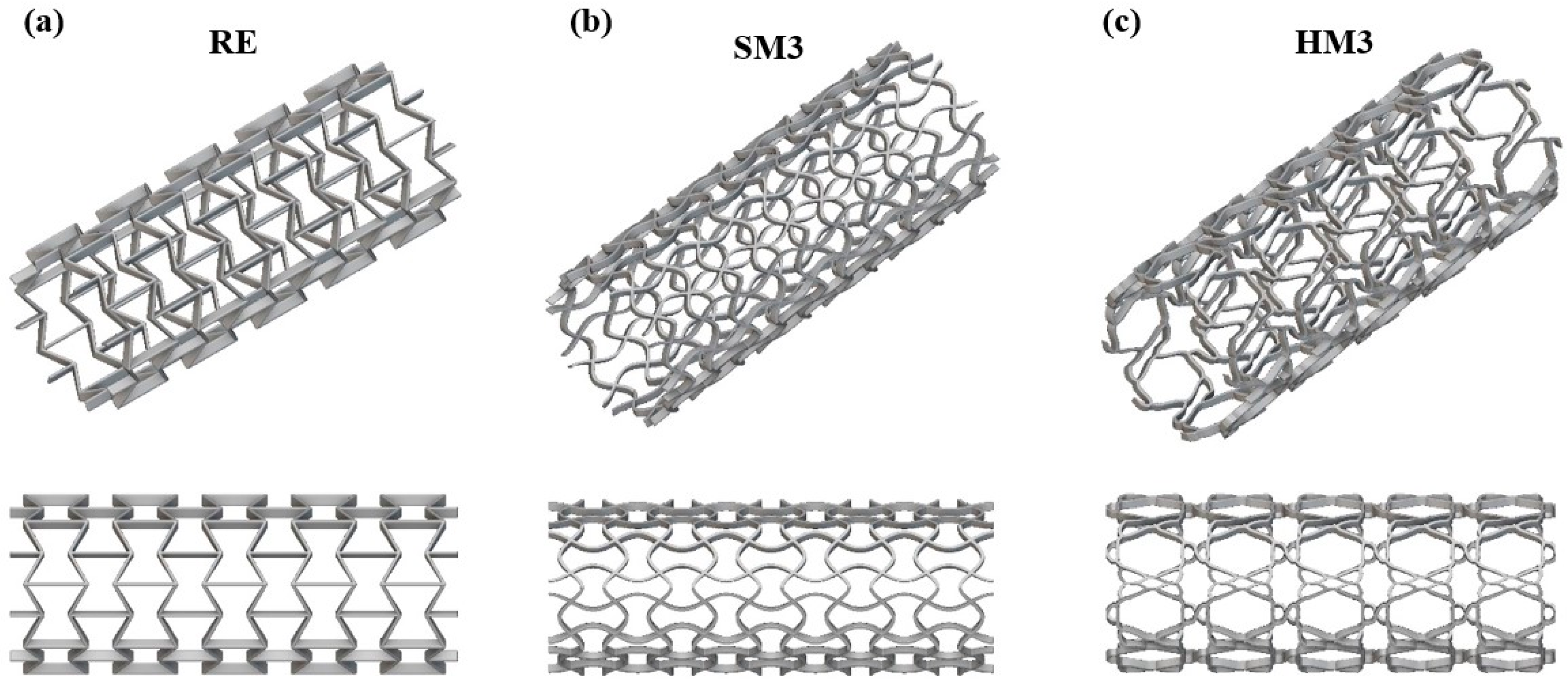
3.2. Arterial Stent Designs
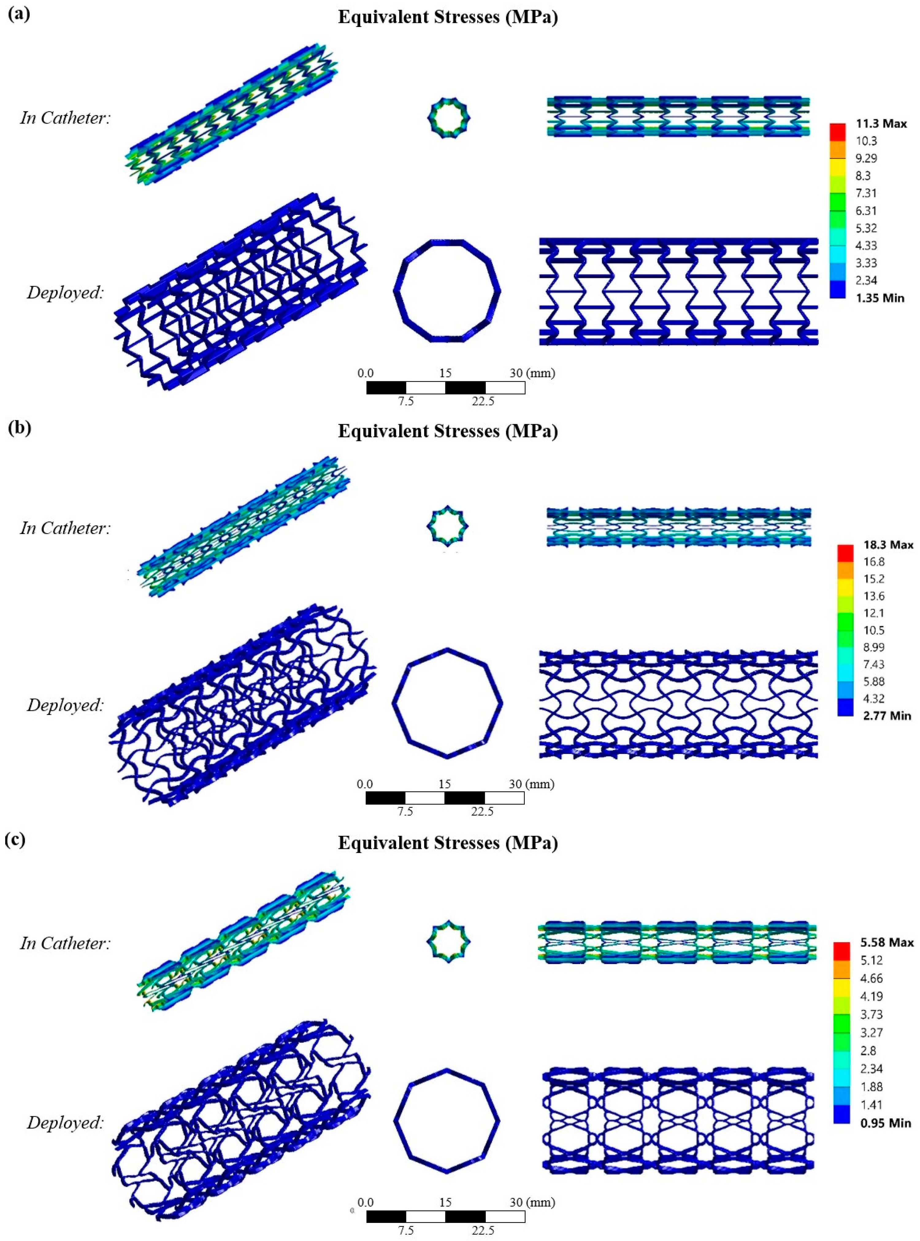
3.3. Finite Element Analysis
4. Conclusions
Author Contributions
Funding
Institutional Review Board Statement
Data Availability Statement
Conflicts of Interest
References
- Kyriakidis, I.F.; Kladovasilakis, N.; Pechlivani, E.M.; Tsongas, K. Mechanical Performance of Recycled 3D Printed Sustainable Polymer-Based Composites: A Literature Review. J. Compos. Sci. 2024, 8, 215. [Google Scholar] [CrossRef]
- Gu, S.; Liu, D.; Zhu, L.; Xie, Y.; Evsyukov, S.A.; Luo, X. Preparation and Characterization of 4D Printable PCL/SEBS-g-MAH Blends with Excellent Mechanical and Shape Memory Properties. Polym. Eng. Sci. 2024, 64, 5719–5736. [Google Scholar] [CrossRef]
- Li, S.; Shan, Y.; Chen, J.; Chen, X.; Shi, Z.; Zhao, L.; He, R.; Li, Y. 3D Printing and Biomedical Applications of Piezoelectric Composites: A Critical Review. Adv. Mater. Technol. 2024, 2401160. [Google Scholar] [CrossRef]
- Backes, E.H.; Harb, S.V.; Beatrice, C.A.G.; Shimomura, K.M.B.; Passador, F.R.; Costa, L.C.; Pessan, L.A. Polycaprolactone Usage in Additive Manufacturing Strategies for Tissue Engineering Applications: A Review. J. Biomed. Mater. Res. Part B Appl. Biomater. 2021, 110, 1479–1503. [Google Scholar] [CrossRef]
- Eldeeb, A.E.; Salah, S.; Elkasabgy, N.A. Biomaterials for Tissue Engineering Applications and Current Updates in the Field: A Comprehensive Review. AAPS PharmSciTech 2022, 23, 267. [Google Scholar] [CrossRef] [PubMed]
- Mondal, D.; Griffith, M.; Venkatraman, S.S. Polycaprolactone-Based Biomaterials for Tissue Engineering and Drug Delivery: Current Scenario and Challenges. Int. J. Polym. Mater. 2016, 65, 255–265. [Google Scholar] [CrossRef]
- Stratton, S.; Shelke, N.B.; Hoshino, K.; Rudraiah, S.; Kumbar, S.G. Bioactive Polymeric Scaffolds for Tissue Engineering. Bioact. Mater. 2016, 1, 93–108. [Google Scholar] [CrossRef]
- Kumar, R.; Singh, R.; Kumar, V.; Ranjan, N.; Gupta, J.; Bhura, N. On 3D Printed Thermoresponsive PCL-PLA Nanofibers Based Architected Smart Nanoporous Scaffolds for Tissue Reconstruction. J. Manuf. Process. 2024, 119, 666–681. [Google Scholar] [CrossRef]
- Constante, G.; Apsite, I.; Alkhamis, H.; Dulle, M.; Schwarzer, M.; Caspari, A.; Synytska, A.; Salehi, S.; Ionov, L. 4D Biofabrication Using a Combination of 3D Printing and Melt-Electrowriting of Shape-Morphing Polymers. ACS Appl. Mater. Interfaces 2021, 13, 12767–12776. [Google Scholar] [CrossRef] [PubMed]
- Wang, Y.; Zhang, X. Vascular restoration therapy and bioresorbable vascular scaffold. Regen. Biomater. 2014, 1, 49–55. [Google Scholar] [CrossRef] [PubMed]
- Wang, L.; Jiao, L.; Pang, S.; Yan, P.; Wang, X.; Qiu, T. The Development of Design and Manufacture Techniques for Bioresorbable Coronary Artery Stents. Micromachines 2021, 12, 990. [Google Scholar] [CrossRef] [PubMed]
- Angioplasty and Stent Placement for the Heart. Available online: https://www.hopkinsmedicine.org/health/treatment-tests-and-therapies/angioplasty-and-stent-placement-for-the-heart (accessed on 23 January 2025).
- Tavakol, M.; Ashraf, S.; Brener, S.J. Risks and complications of coronary angiography: A comprehensive review. Glob. J. Health Sci. 2012, 4, 65–93. [Google Scholar] [CrossRef] [PubMed]
- Pandey, H.; Mohol, S.S.; Kandi, R. 4D Printing of Tracheal Scaffold Using Shape-Memory Polymer Composite. Mater. Lett. 2022, 329, 133238. [Google Scholar] [CrossRef]
- Bonetti, L.; Natali, D.; Pandini, S.; Messori, M.; Toselli, M.; Scalet, G. 4D Printing of Semi-Crystalline Crosslinked Polymer Networks with Two-Way Shape Memory Effect. Mater. Des. 2024, 238, 112725. [Google Scholar] [CrossRef]
- Bouguermouh, K.; Habibi, M.; Laperrière, L. 4D Printing of Fiber-Reinforced Auxetic Structures: The Building Blocks: A Review. Smart Mater. Struct. 2024, 33, 063001. [Google Scholar] [CrossRef]
- Zhou, Y.; Zhou, D.; Cao, P.; Zhang, X.; Wang, Q.; Wang, T.; Li, Z.; He, W.; Ju, J.; Zhang, Y. 4D Printing of Shape Memory Vascular Stent Based on ΒCD-G-Polycaprolactone. Macromol. Rapid Commun. 2021, 42, 2100176. [Google Scholar] [CrossRef]
- He, W.; Zhou, D.; Gu, H.; Qu, R.; Cui, C.; Zhou, Y.; Wang, Y.; Zhang, X.; Wang, Q.; Wang, T.; et al. A Biocompatible 4D Printing Shape Memory Polymer as Emerging Strategy for Fabrication of Deployable Medical Devices. Macromol. Rapid Commun. 2022, 44, e2200553. [Google Scholar] [CrossRef]
- Song, M.; Li, S.; Zhu, G.; Guo, J. Compatibilised and Toughened of PLA/PCL Blends via Modified-Chitosan Linking Amorphous Regions: 4D Printing and Shape Memory Processes. Polym. Test. 2023, 125, 108105. [Google Scholar] [CrossRef]
- Huang, L.; Sheng, Y.; Mo, Q.; Zhang, S.; Zheng, Y.; Wang, B.; Huang, C.; Duan, Q.; Zhao, H. Poly(Lactic Acid)/Polycaprolactone-Based Self-Programmed Photothermal Responsive Shape Memory Polymers. React. Funct. Polym. 2024, 202, 105990. [Google Scholar] [CrossRef]
- Rahmatabadi, D.; Aberoumand, M.; Soltanmohammadi, K.; Soleyman, E.; Ghasemi, I.; Baniassadi, M.; Abrinia, K.; Bodaghi, M.; Baghani, M. 4D Printing-Encapsulated Polycaprolactone–Thermoplastic Polyurethane with High Shape Memory Performances. Adv. Eng. Mater. 2022, 25, 2201309. [Google Scholar] [CrossRef]
- Rahmatabadi, D.; Aberoumand, M.; Soltanmohammadi, K.; Soleyman, E.; Ghasemi, I.; Baniassadi, M.; Abrinia, K.; Bodaghi, M.; Baghani, M. Influence of Programming and Recovery Parameters on Compressive Behaviors of 4D Printed Bio-compatible PVC-PCL Blends. Adv. Eng. Mater. 2024, 26, 2400301. [Google Scholar] [CrossRef]
- Liu, H.; He, H.; Huang, B. Favorable Thermoresponsive Shape Memory Effects of 3D Printed Poly(Lactic Acid)/Poly(Ε-Caprolactone) Blends Fabricated by Fused Deposition Modeling. Macromol. Mater. Eng. 2020, 305, 2000295. [Google Scholar] [CrossRef]
- Peng, B.; Yang, Y.; Ju, T.; Cavicchi, K.A. Fused Filament Fabrication 4D Printing of a Highly Extensible, Self-Healing, Shape Memory Elastomer Based on Thermoplastic Polymer Blends. ACS Appl. Mater. Interfaces 2020, 13, 12777–12788. [Google Scholar] [CrossRef] [PubMed]
- Zhu, L.; Liu, D.; Luo, X.; Zhou, J.; Zheng, J.; Lai, C. Preparation and Characterization of Thermo-responsive Shape Memory Polycaprolactone/Poly(Ethylene-co-octene) Blends for 4D Printing. Polym. Eng. Sci. 2023, 63, 2828–2840. [Google Scholar] [CrossRef]
- Li, A.; Chen, X.-G.; Zhang, L.-Y.; Zhang, Y.-F. Temperature and Infill Density Effects on Thermal, Mechanical and Shape Memory Properties of Polylactic Acid/Poly(ε-Caprolactone) Blends for 4D Printing. Materials 2022, 15, 8838. [Google Scholar] [CrossRef] [PubMed]
- Kyriakidis, I.F.; Kladovasilakis, N.; Pechlivani, E.M.; Korlos, A.; David, C.; Tsongas, K. In Situ Investigation of Tensile Response for Inconel 718 Micro-Architected Materials Fabricated by Selective Laser Melting. Materials 2024, 17, 4433. [Google Scholar] [CrossRef] [PubMed]
- Dong, K.; Panahi-Sarmad, M.; Cui, Z.; Huang, X.; Xiao, X. Electro-Induced Shape Memory Effect of 4D Printed Auxetic Composite Using PLA/TPU/CNT Filament Embedded Synergistically with Continuous Carbon Fiber: A Theoretical & Experimental Analysis. Compos. Part B Eng. 2021, 220, 108994. [Google Scholar] [CrossRef]
- Yousuf, M.H.; Abuzaid, W.; Alkhader, M. 4D Printed Auxetic Structures with Tunable Mechanical Properties. Addit. Manuf. 2020, 35, 101364. [Google Scholar] [CrossRef]
- Ren, L.; Wu, W.; Ren, L.; Song, Z.; Liu, Q.; Li, B.; Wu, Q.; Zhou, X. 3D Printing of Auxetic Metamaterials with High-Temperature and Programmable Mechanical Properties. Adv. Mater. Technol. 2022, 7, 2101546. [Google Scholar] [CrossRef]
- Hassanin, H.; Abena, A.; Elsayed, M.A.; Essa, K. 4D Printing of NiTi Auxetic Structure with Improved Ballistic Performance. Micromachines 2020, 11, 745. [Google Scholar] [CrossRef] [PubMed]
- Kladovasilakis, N.; Tsongas, K.; Karalekas, D.; Tzetzis, D. Architected Materials for Additive Manufacturing: A Comprehensive Review. Materials 2022, 15, 5919. [Google Scholar] [CrossRef] [PubMed]
- Zhao, S.; Hu, H.; Kamrul, H.; Chang, Y.; Zhang, M. Development of auxetic warp knitted fabrics based on reentrant geometry. Text. Res. J. 2020, 90, 344–356. [Google Scholar] [CrossRef]
- Körner, C.; Liebold-Ribeiro, Y. A systematic approach to identify cellular auxetic materials. Smart Mater. Struct. 2014, 24, 025013. [Google Scholar] [CrossRef]
- Ren, X.; Das, R.; Tran, P.; Ngo, T.D.; Xie, Y.M. Auxetic metamaterials and structures: A review. Smart Mater. Struct. 2018, 27, 023001. [Google Scholar] [CrossRef]
- Litmanovich, D.; Bankier, A.A.; Cantin, L.; Raptopoulos, V.; Boiselle, P.M. CT and MRI in Diseases of the Aorta. Vasc. Interv. Radiol. 2009, 193, 928–940. [Google Scholar] [CrossRef] [PubMed]
- Ebrahimi, M.S.; Noruzi, M.; Hamzehei, R.; Etemadi, E.; Hashemi, R. Revolutionary auxetic intravascular medical stents for angioplasty applications. Mater. Des. 2023, 235, 112393. [Google Scholar] [CrossRef]
- Lyu, J.S.; Lee, J.S.; Han, J. Development of a Biodegradable Polycaprolactone Film Incorporated with an Antimicrobial Agent via an Extrusion Process. Sci. Rep. 2019, 9, 20236. [Google Scholar] [CrossRef] [PubMed]
- Díaz, E.; Sandonis, I.; Blanca Valle, M. In Vitro Degradation of Poly(caprolactone)/nHA Composites. J. Nanomater. 2014, 8, 802435. [Google Scholar] [CrossRef]
- Kladovasilakis, N.; Charalampous, P.; Boumpakis, A.; Kontodina, T.; Tsongas, K.; Tzetzis, D.; Kostavelis, I.; Givissis, P.; Tzovaras, D. Development of biodegradable customized tibial scaffold with advanced architected materials utilizing additive manufacturing. J. Mech. Behav. Biomed. Mater. 2023, 141, 105796. [Google Scholar] [CrossRef]
- Cantrell, J.T.; Rohde, S.; Damiani, D.; Gurnani, R.; DiSandro, L.; Anton, J.; Young, A.; Jerez, A.; Steinbach, D.; Kroese, C. Experimental Characterization of the Mechanical Properties of 3D-Printed ABS and Polycarbonate Parts. Adv. Opt. Methods Exp. Mech. 2017, 3, 89–105. [Google Scholar] [CrossRef]
- Zaldivar, R.J.; Witkin, D.B.; Mclouth, T.; Patel, D.N.; Schmitt, K.; Nokes, J.P. Influence of Processing and Orientation Print Effects on the Mechanical and Thermal Behavior of 3D-Printed ULTEM® 9085 Material. J. Addit. Manuf. 2017, 13, 71–80. [Google Scholar] [CrossRef]
- Kladovasilakis, N.; Tsongas, K.; Kostavelis, I.; Tzovaras, D.; Tzetzis, D. Effective mechanical properties of additive manufactured triply periodic minimal surfaces: Experimental and finite element study. Int. J. Adv. Manuf. Technol. 2022, 121, 7169–7189. [Google Scholar] [CrossRef]
- Kladovasilakis, N.; Tsongas, K.; Kostavelis, I.; Tzovaras, D.; Tzetzis, D. Effective Mechanical Properties of Additive Manufactured Strut-Lattice Structures: Experimental and Finite Element Study. Adv. Eng. Mater. 2022, 24, 2100879. [Google Scholar] [CrossRef]
- Gibson, L.J.; Ashby, M.F. Cellular Solids: Structure and Properties, 2nd ed.; Cambridge University Press: Cambridge, UK, 1997. [Google Scholar]
- Siviour, C.R.; Jordan, J.L. High strain rate mechanics of polymers: A review. J. Dyn. Behav. Mater. 2016, 2, 15–32. [Google Scholar] [CrossRef]
- Kladovasilakis, N.; Tsongas, K.; Tzetzis, D. Development of Novel Additive Manufactured Hybrid Architected Materials and Investigation of Their Mechanical Behavior. Mech. Mater. 2023, 176, 104525. [Google Scholar] [CrossRef]
- Available online: https://www.goremedical.com/eu/resource/22618651-en (accessed on 23 January 2025).
- Granta Material Intelligence. Granta’s CES EduPack 2012; Granta Design Limited: Cambridge, UK, 2007. [Google Scholar]


| Auxetic Architected Materials | Wall Thickness (mm) | Relative Density |
|---|---|---|
| RE | 0.4 | 15% |
| 0.8 | 30% | |
| 1.2 | 45% | |
| SM3 | 0.4 | 20% |
| 0.8 | 35% | |
| 1.2 | 50% | |
| HM3 | 0.4 | 15% |
| 0.8 | 30% | |
| 1.2 | 45% |
| 3D Printing Parameters | |
|---|---|
| Nozzle diameter | 0.4 mm |
| Cold Extrusion | Enabled (M302) |
| Extrusion temperature | 90 °C |
| Build platform temperature | 40 °C |
| Layer height | 0.2 mm |
| Infill percentage | Solid |
| Print speed | 40 mm/s |
| Platform adhesion | Brim (5 mm) |
| Material Properties | |
|---|---|
| Density | 1.2 g/cm3 |
| Poisson’s ratio | 0.45 |
| Elastic modulus | 345 MPa |
| Yield strength | 14 MPa |
| Ultimate tensile strength | 17 MPa |
| Compressive strength | 25 MPa |
| Elongation at break | 460% |
| Auxetic Architected Materials | Elastic Modulus [MPa] | Yield Stress [MPa] | UTS [MPa] | Compressive Strength [MPa] | Relative Density |
|---|---|---|---|---|---|
| RE | 1.9 ± 0.1 | 0.49 ± 0.05 | 0.62 ± 0.05 | 0.16 ± 0.05 | 15% |
| 3.6 ± 0.1 | 1.25 ± 0.1 | 1.56 ± 0.1 | 0.55 ± 0.05 | 30% | |
| 5.8 ± 0.3 | 1.61 ± 0.1 | 2.01 ± 0.1 | 1.26 ± 0.1 | 45% | |
| SM3 | 6.5 ± 0.3 | 1.19 ± 0.1 | 1.49 ± 0.1 | 0.44 ± 0.05 | 20% |
| 12 ± 0.5 | 2.16 ± 0.1 | 2.68 ± 0.1 | 1.24 ± 0.1 | 35% | |
| 19 ± 0.5 | 3.49 ± 0.2 | 4.37 ± 0.2 | 2.38 ± 0.1 | 50% | |
| HM3 | 1.2 ± 0.1 | 0.49 ± 0.05 | 0.53 ± 0.05 | 0.13 ± 0.05 | 15% |
| 3.1 ± 0.1 | 1.28 ± 0.1 | 1.59 ± 0.1 | 0.67 ± 0.05 | 30% | |
| 10 ± 0.5 | 3.43 ± 0.2 | 4.28 ± 0.2 | 1.24 ± 0.1 | 45% |
| Auxetic Architected Materials | Elastic Modulus [MPa] | Yield Stress [MPa] | UTS [MPa] | Compressive Strength [MPa] | ||||
|---|---|---|---|---|---|---|---|---|
| CEM | n | CYS | n | CUTS | n | CCS | n | |
| RE | 0.037 | 1.006 | 0.248 | 0.960 | 0.248 | 0.959 | 0.245 | 1.983 |
| SM3 | 0.126 | 1.2 | 0.563 | 1.227 | 0.563 | 1.227 | 0.340 | 1.834 |
| HM3 | 0.255 | 2.729 | 1.231 | 2.077 | 1.229 | 2.075 | 0.199 | 1.726 |
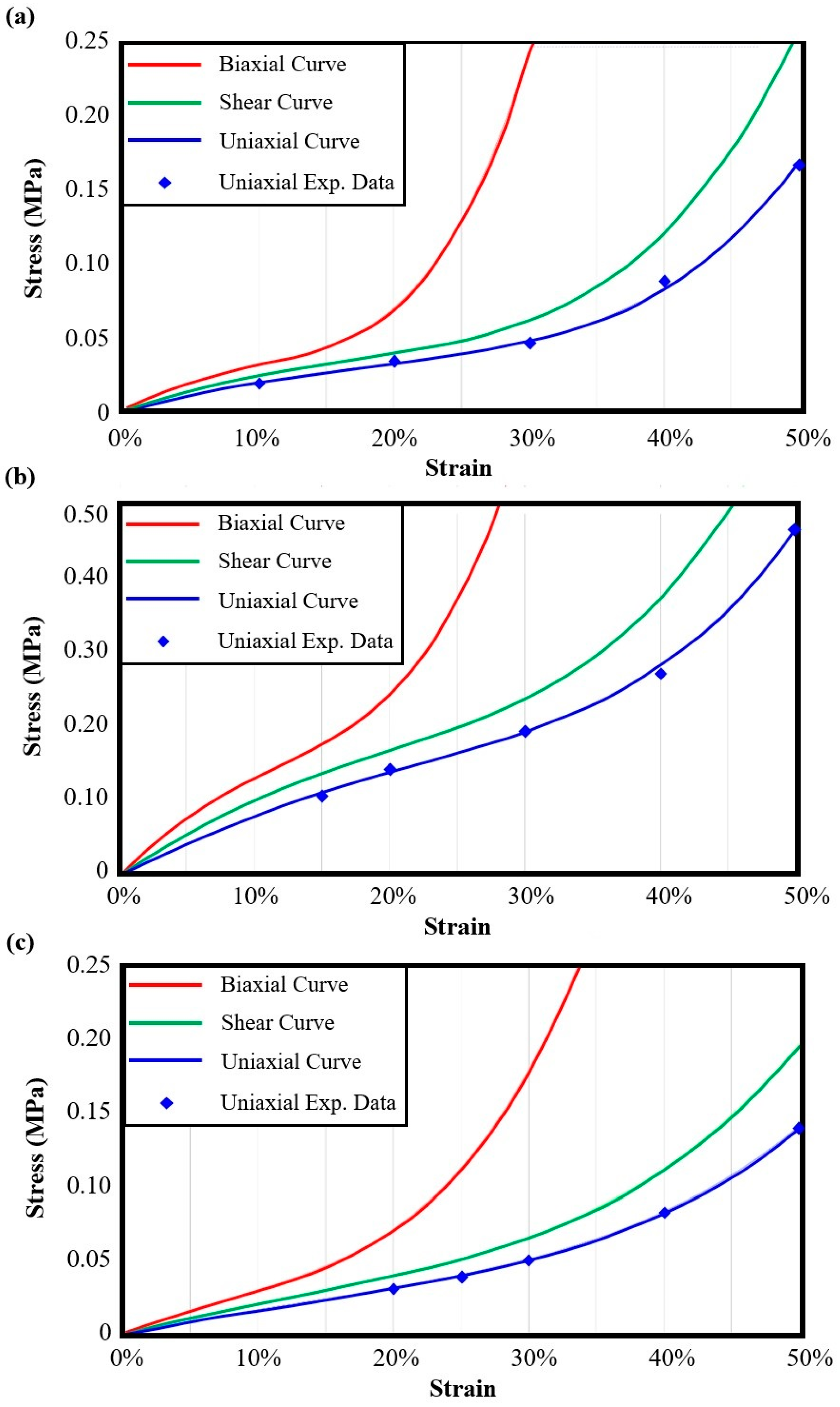
| Auxetic Architected Materials | 3rd-Order Yeoh Model Constants [MPa] | ||
|---|---|---|---|
| C1 | C2 | C3 | |
| RE | 0.0356 | −0.0352 | 0.0818 |
| SM3 | 0.1374 | −0.0772 | 0.1537 |
| HM3 | 0.0265 | 0.0022 | 0.0304 |
Disclaimer/Publisher’s Note: The statements, opinions and data contained in all publications are solely those of the individual author(s) and contributor(s) and not of MDPI and/or the editor(s). MDPI and/or the editor(s) disclaim responsibility for any injury to people or property resulting from any ideas, methods, instructions or products referred to in the content. |
© 2025 by the authors. Licensee MDPI, Basel, Switzerland. This article is an open access article distributed under the terms and conditions of the Creative Commons Attribution (CC BY) license (https://creativecommons.org/licenses/by/4.0/).
Share and Cite
Kladovasilakis, N.; Kyriakidis, I.F.; Tzimtzimis, E.K.; Pechlivani, E.M.; Tsongas, K.; Tzetzis, D. Development of 4D-Printed Arterial Stents Utilizing Bioinspired Architected Auxetic Materials. Biomimetics 2025, 10, 78. https://doi.org/10.3390/biomimetics10020078
Kladovasilakis N, Kyriakidis IF, Tzimtzimis EK, Pechlivani EM, Tsongas K, Tzetzis D. Development of 4D-Printed Arterial Stents Utilizing Bioinspired Architected Auxetic Materials. Biomimetics. 2025; 10(2):78. https://doi.org/10.3390/biomimetics10020078
Chicago/Turabian StyleKladovasilakis, Nikolaos, Ioannis Filippos Kyriakidis, Emmanouil K. Tzimtzimis, Eleftheria Maria Pechlivani, Konstantinos Tsongas, and Dimitrios Tzetzis. 2025. "Development of 4D-Printed Arterial Stents Utilizing Bioinspired Architected Auxetic Materials" Biomimetics 10, no. 2: 78. https://doi.org/10.3390/biomimetics10020078
APA StyleKladovasilakis, N., Kyriakidis, I. F., Tzimtzimis, E. K., Pechlivani, E. M., Tsongas, K., & Tzetzis, D. (2025). Development of 4D-Printed Arterial Stents Utilizing Bioinspired Architected Auxetic Materials. Biomimetics, 10(2), 78. https://doi.org/10.3390/biomimetics10020078