Article

Parametric Design and Mechanical Characterization of a Selective Laser Sintering Additively Manufactured Biomimetic Ribbed Dome Inspired by the Chorion of Lepidopteran Eggs

by
Alexandros Efstathiadis
1,
Ioanna Symeonidou
1,
Emmanouil K. Tzimtzimis
2,
Dimitrios Avtzis
3,
Konstantinos Tsongas
4 and
Dimitrios Tzetzis
2,*
1
Department of Architecture, University of Thessaly, 38221 Volos, Greece
2
Digital Manufacturing and Materials Characterization Laboratory, School of Science and Technology, International Hellenic University, 57001 Thermi, Greece
3
Forest Research Institute, Hellenic Agricultural Organization Demeter, 57006 Vassilika, Greece
4
Department of Industrial Engineering and Management, School of Engineering, International Hellenic University, 57001 Thessaloniki, Greece
*
Author to whom correspondence should be addressed.
Biomimetics 2025, 10(1), 1; https://doi.org/10.3390/biomimetics10010001
Submission received: 27 November 2024 / Revised: 17 December 2024 / Accepted: 19 December 2024 / Published: 24 December 2024
(This article belongs to the Special Issue Biomimetic 3D/4D Printing)

Abstract

:
The current research aims to analyze the shape and structural features of the eggs of the lepidoptera species Melitaea sp. (Lepidoptera, Nympalidae) and develop design solutions through the implementation of a novel strategy of biomimetic design. Scanning electron microscopy (SEM) analysis of the chorion reveals a medial zone that forms an arachnoid grid resembling a ribbed dome with convex longitudinal ribs and concave transverse ring members. A parametric design algorithm was created with the aid of computer-aided design (CAD) software Rhinoceros 3D and Grasshopper3D in order to abstract and emulate the biological model. A series of physical models were manufactured with variations in geometric parameters like the number of ribs and rings, their thickness, and curvature. Selective laser sintering (SLS) technology and Polyamide12 (nylon) material were utilized for the prototyping process. Quasi-static compression testing was carried out in conjunction with finite element analysis (FEA) to investigate the deformation patterns and stress dispersion of the models. The biomimetic ribbed dome appears to significantly dampen the snap-through behavior that is observed in typical solid and lattice domes, decreasing dynamic stresses developed during the response and preventing catastrophic failure of the structure. Increasing the curvature of the ring segments further reduces the snap-through phenomenon and improves the overall strength. However, excessive curvature has a negative effect on the maximum sustained load. Increasing the number and thickness of the transverse rings and the number of the longitudinal ribs also increases the strength of the dome. However, excessive increase in the rib radius leads to more acute snap-through behavior and an earlier failure. The above results were validated using respective finite element analyses.

1. Introduction

Biomimicry is a relatively new interdisciplinary field of science that studies natural models and strategies, draws inspiration from them, and attempts to apply them to contemporary design and engineering challenges [1]. In order to facilitate the practice of biomimicry and bridge the knowledge gap between the different disciplines involved in the process [2], specialized methodological tools have been developed, like the Biomimicry Taxonomy [3,4,5]. Strategies of biomimetic design have also been proposed, like the top-down (or technology pull) and bottom-up (or biology push) methods developed by Knippers, both of which are characterized by a linear approach regarding the steps of the process [6,7,8]. The biomimetic design spiral is another strategy of biomimetic design developed by the Biomimicry Institute that attempts to tackle the challenge of biomimicry through a spiral and iterative process [4].
Algorithmic design is an iterative design process that involves a program or algorithm that meets certain user-defined parameters as input [9]. The output is an infinite set of possible design solutions [10]. The designer evaluates the output and has the ability to modify the input parameters or even the algorithmic source code in order to optimize the end result according to his design goals [11] and to data collected during the technical implementation process [12]. It has also enabled the generation of complex geometric models that would otherwise be extremely arduous to create [13]. Algorithmic design can find application in biomimetic design and in the strategies that were described earlier, particularly at the stages of abstraction and emulation of biological models.
Conventional manufacturing methods are unable to produce intricate biomimetic structures due to their technological limitations, which has also hampered the growth of biomimetic research and the development and application of biomimetic design solutions [14]. However, developments in additive manufacturing (AM) technologies have opened up new possibilities and made it possible to build complex structures and novel materials that were previously impossible [15,16]. More specifically, selective laser sintering (SLS) technology uses a laser beam to sinter a polymer powder and fuse the particles together, thus creating layer by layer the required product [17], a technology that has found application in the medical material technology and industrial sectors [18,19,20]. The advantages of the SLS technology include great design freedom, the complexity and high accuracy of printed parts, a variety of materials, minimal material waste, supportless printing, and good mechanical properties [21,22,23,24]. A disadvantage of the process, which is common to all laser-based AM technologies, is the high printing times [25].
An egg is an organic, hierarchical structure [26] with the function of carrying and incubating an embryo until its hatching [27]. Eggs are laid by various animals, ranging from insects and reptiles to birds, something that explains the great structural variety [28,29,30,31,32]. As eggs are essential not only for the nourishment, oxygen, and excretion exchange of the embryo [33,34] but also, more importantly, for protecting the embryo from unfavorable environmental conditions and threats, like crushing or puncturing [35,36], they have developed some excellent mechanical properties and features [37].
The goal of the present research is to study the structure of eggs of the nymphalid Melitaea sp. and to extract design solutions through the implementation of a novel strategy of biomimetic design. It also aims to incorporate algorithmic design tools in the abstraction phase of the biological model as it is transferred into a parametric digital model. Subsequently, the SLS additive manufacturing technology was selected in an attempt to integrate 3D printing technologies into the technical implementation stage of the biologically inspired design. Lastly, mechanical testing coupled with finite element analysis (FEA) was conducted to evaluate the technical properties of the biomimetic structure.

2. Materials and Methods

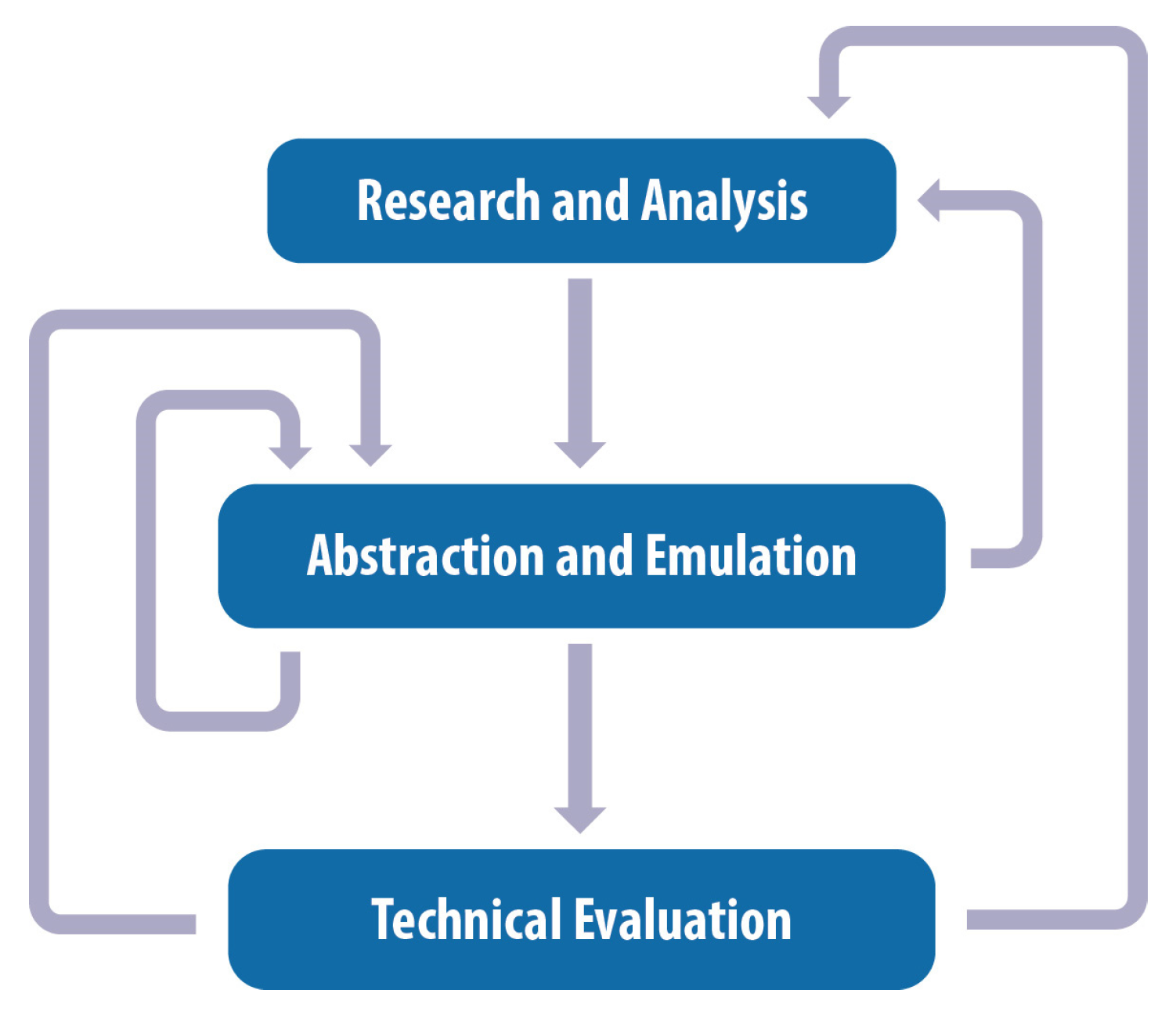
2.1. Novel Biomimetic Design Strategy

A novel biomimetic design strategy has been developed as part of the present research and has been documented in previously published work [38,39,40,41,42]. The first stage is the “Research and Analysis” of the biological model, which comprises biological research, the identification of biological structures of interest, and their subsequent analysis with means of microscopic analysis. This is followed by the “Abstraction and Emulation” stage, which consists of the extraction of the biological model and its transfer into a digital 3D model with the aid of computational design. The last stage is the “Technical Evaluation” of the biomimetic design concept, which involves creating prototypes with the aid of 3D printing technologies and assessing the mechanical behavior of the structure with appropriate testing and simulations. The three stages of the methodology are not linear, but instead, they are interconnected by bi-directional loops of feedback, as shown in Figure 1, where each phase informs the rest, and revisiting a previous stage is often necessary for optimization purposes. This kind of approach constitutes a significant step over existing strategies that are either linear or spiral [4,6,7,8].

2.2. Research and Analysis

More specifically, biological research was initially conducted with the aid of specialized biomimetic tools and databases like AskNature [3], along with traditional literature resources. It was determined that the chorion of lepidopteran eggs is a hierarchical structure that could potentially serve as a valuable source of biomimetic design inspiration [34,43,44]. Melitaea is a genus of brush-footed butterflies (Nymphalidae) that comprises several species with worldwide distribution [45]. In Greece, this genus is represented by eight species that occur diversely all over the country [46]. The egg masses of Melitaea sp. were collected in the suburban forest of Thessaloniki and were immediately brought to the laboratory of Forest Entomology (Forest Research Institute, Hellenic Agricultural Organization Demeter). After carefully removing the egg masses from the plant tissues that were attached, the eggs were lyophilized in 2 mL Eppendorf vials.
Analysis of the lepidopteran egg structure at the microscopic level was conducted using the digital microscope Dino-Lite Pro HR-AD7013MZT (Dino-Lite Europe, Almere, The Netherlands). Furthermore, the microstructure of the chorion was examined under the Phenom ProX Desktop Scanning Electron Microscope (SEM) (Thermo Fisher Scientific, Waltham, MA, USA). Chorion samples were coated with gold (Au) at the Quorum SC7620 Sputter Coater (Quorum Technologies, Laughton, UK) to prevent thermal damage caused by electrical charging and were mounted on double-sided carbon tape [47]. Further analysis of the microscopic imaging was conducted on the ImageJ (v.1.53t, National Institutes of Health, Bethesda, MD, USA) software.

2.3. Abstraction and Emulation

Computer-aided design (CAD) software Rhinoceros 3D (v.Rhino 7, 7.1.20343.09491, Robert McNeel & Associates, Seattle, WA, USA) and the embedded visual programming environment Grasshopper 3D (v.1.0.0007, Robert McNeel & Associates, Seattle, WA, USA) were utilized for the abstraction of the biological model and its translation into a digital, three-dimensional model. Additionally, the volumetric modeling plug-in Denrdo (v1.0.0, ECR Labs, Los Angeles, CA, USA) was utilized, which has the advantage of generating light volume data structures that are faster to compute [48]. A series of models were generated with variable geometric parameters.

2.4. Technical Evaluation

Selective laser sintering (SLS) technology was selected for the fabrication of physical specimens of the biomimetic models. The Sinterit Lisa rev.A SLS printer (Sinterit sp. z o.o., Krakow, Poland) was used in combination with commercial Polyamide 12 (nylon) powder (Sinterit sp. z o.o., Krakow, Poland). An advantage of the SLS technology is that there is no need to add support, as the powder itself performs this role. Avoiding the use of supports was considered necessary due to the geometric intricacies of the structure. The nesting and slicing of the models were carried out on the Sinterit Studio slicer (v.1.8.1.1, Sinterit sp. z o.o., Krakow, Poland). The specimens were carefully extracted from the powder “cake” and cleaned in order to avoid damaging the overall structure. For the same reason, no sandblasting was employed in the process.
Three specimens of each model were tested for reliability purposes under uniaxial quasi-static concentrated compression loading at room temperature at a universal testing machine (M500-50AT Testometric Company, Rochdale, UK) equipped with a 50 kn load cell and a strain rate of 5 mm/min in order to identify trends in the mechanical performance of the biomimetic structure in relation to changes in its topological characteristics. The mechanical characteristics of the biomimetic ribbed domes were explored using the ANSYS™ software (ANSYS, Inc., Canonsburg, PA, USA). To precisely replicate the mechanical response of the domes, an explicit dynamic analysis was executed, as it was vital for representing their extensive distortions and bi-linear material behavior. To confirm results unaffected by mesh density, a convergence assessment was executed. This analysis indicated that stress convergence was attained with roughly 250,000 nodes and 670,000 elements for each validation model.

3. Biomimetic Design Process

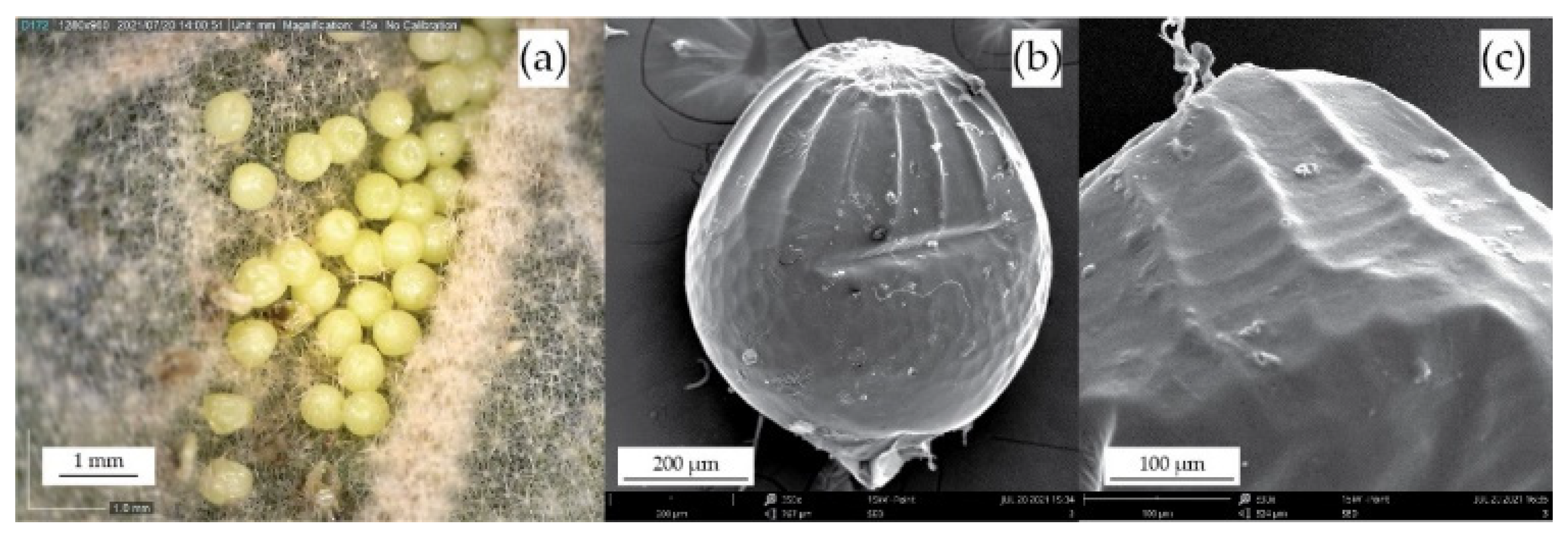
3.1. Morphological Analysis of the Biological Sample

The eggs of Melitaea sp. have the shape of slight prolate spheres with a diameter ranging from 0.55 mm to 0.63 mm, as illustrated in Figure 2a,b and documented in relevant literature [43]. SEM analysis of the eggs reveals that the outer layer of the egg, known as the chorion, is a hierarchical structure [49], as seen in Figure 2b. It is characterized by three distinct areas: the apical zone, consisting of elongated hexagons (also known as the rosette); a medial zone, consisting of curved longitudinal ribs and transverse rings; and a basal zone, formed by irregular hexagons [38]. The convex ribs, along with the concave rings, form an arachnoid micro-grid pattern resembling a ribbed dome [34,50] that can be distinguished in Figure 2c. The role of this structure is to enhance the structural stability of the eggshell [27,35]. The rib count was calculated at 16–18 and the ring count at 12–14, while the ribs were more pronounced than the rings with a relative thickness ratio of 1.51–1.62. This arachnoid pattern is what distinguishes the specific biological structure and served as a source of inspiration for the design of a biomimetic ribbed domed.

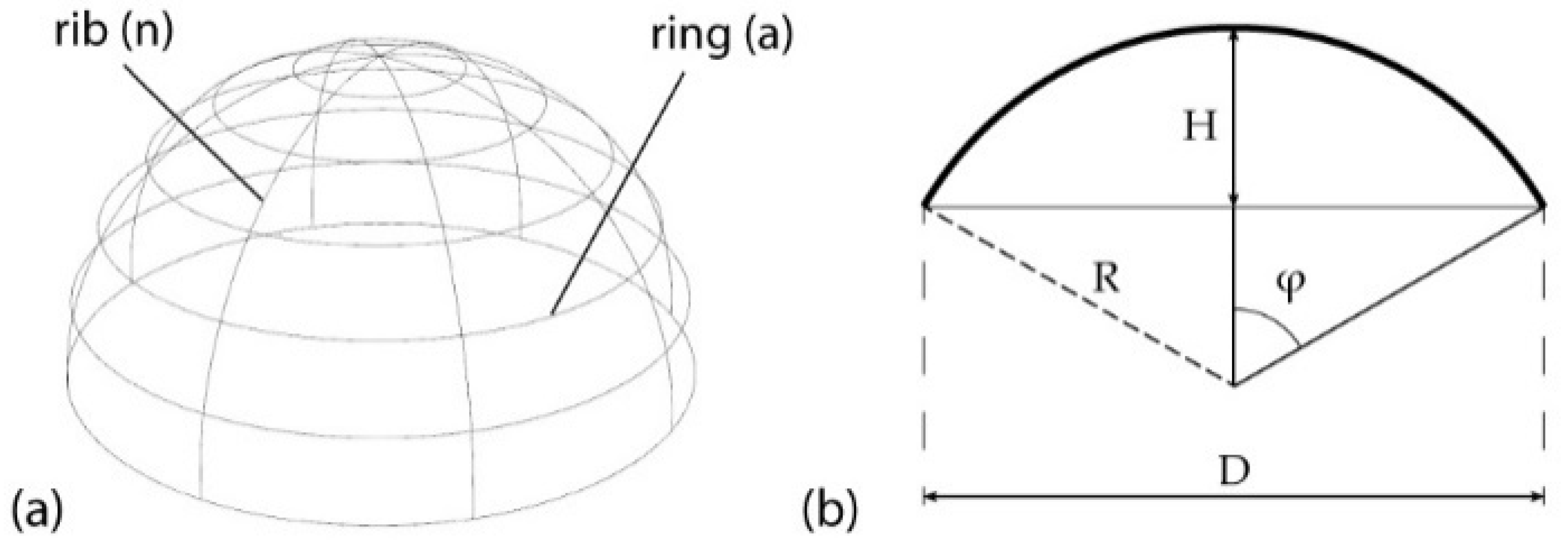
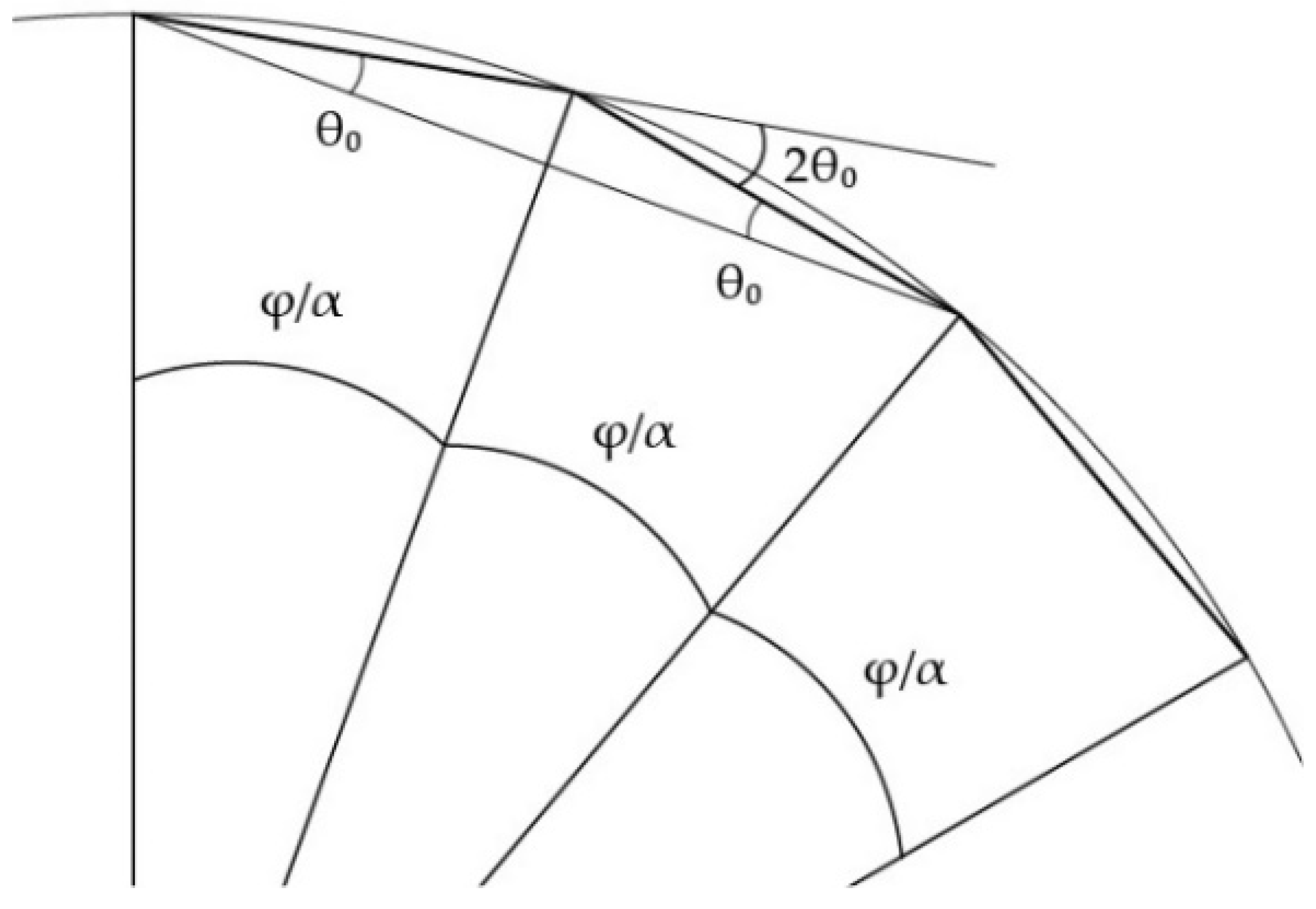
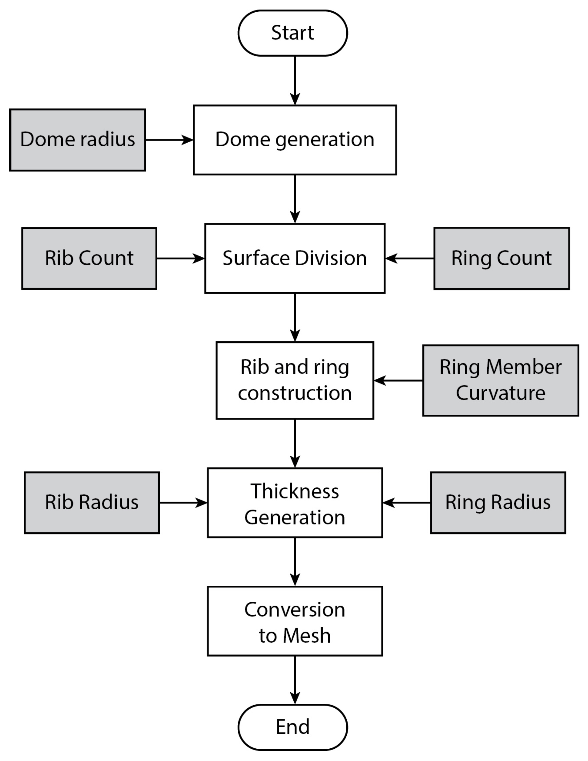
3.2. Geometric Characterization of a Ribbed Dome

An advantage of dome structures is that they can cover the largest volume of space with the smallest use of material, resulting in constructions of minimal weight, while the nonaxial orientation of their elements provides excellent deformation performance to the overall structure through even propagation of stresses [51,52]. A ribbed dome generally comprises ribs and rings, where ribs are components that are distributed in the longitudinal direction while rings are components laid in the transverse direction [53]. Thus, typical ribbed domes are characterized by the following geometric parameters, as illustrated in Figure 3 [52]:
  • The number of ribs (n) and number of rings (a).
  • The height (H) and the span (D) of the dome.
Other parameters that define a dome is the total subtended angle, which is calculated from its height-to-span ratio, more specifically from the following equation [54]:
tan φ = 4 × D H D H 2 4   ,
Lastly, the angle that is created between rib members separated by the rings, as illustrated in Figure 4 is equal to 2θ0 [55]
θ 0 = φ 2 α  
where α is the number of rings.

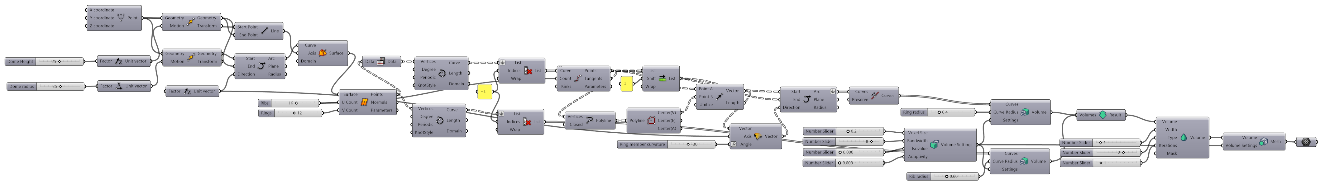
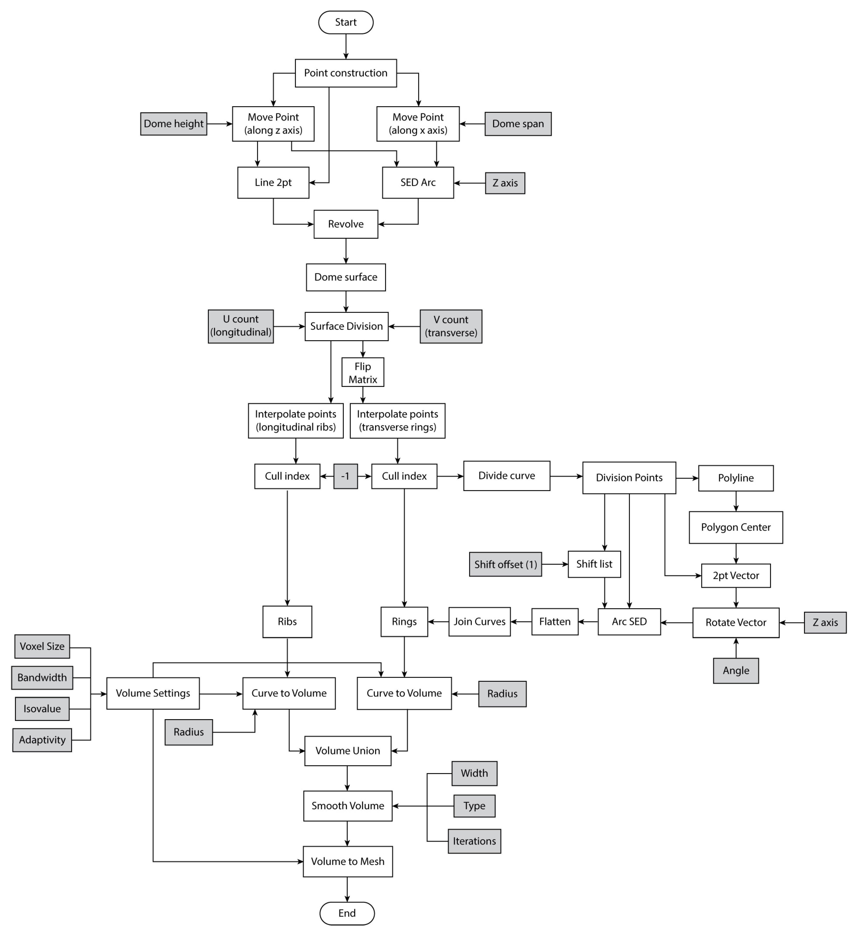
3.3. Algorithmic Design

A parametric algorithm was created with the aid of Grasshopper visual programming language, which produces a digital model mimicking the chorion’s medial zone structure. Figure 5 shows the complete definition with all its components as found on the Grasshopper canvas. At the top algorithmic level, illustrated in Figure 6, a dome is initially created with a user-defined radius. The next step is to subdivide the surface of the dome, subsequently generating longitudinal ribs and transverse rings with variable counts. The curvature of the individual concave ring members can also be customized. In the end, thickness is given to the ribs and rings, and a final mesh is created.
A detailed, lower-level workflow diagram of the design algorithm can be found in Figure 7. Two points are initially constructed along the x axis and along the z axis of a cartesian three-dimensional space. These two points then form the start and end points, respectively, of an arc with a tangent at the start point, coincident with the z direction. The arc is then revolved, and a dome geometry is formed. The revolution axis is a line with the origin point as the start point and the z axis as the direction.
Next, the surface of the dome is divided into segments. The U and V divisions are customizable and determine the number of the final ribs and rings, respectively. The output points are then interpolated to form longitudinal curves. At the same time, their data matrix is flipped and interpolated to construct transverse curves from the same point set. The interpolation process creates a repeated curve that is culled.
Subsequently, divisions along the transverse curves are created, equal in number to the longitudinal curves. Closed polylines are constructed from the division points, and the centers of these polygons are extracted. Afterward, SED (Start, End, Direction) arcs are formed with the division points as the start points and the division points list offset by a count of 1 as the endpoints. The curvature of each arc is determined by the direction of a tangent vector that has the same starting point as the arc, the polygon’s center as an ending point, and can be rotated around the z axis to change the curve of the arc. In the end, the resulting curves are flattened and joined.
In the final step of the biomimetic dome generation process, thickness is added to the longitudinal ribs and transverse rings with the application of specific components from the Dendro plug-in, like “Curve to Volume”. Dendro Volumes are created for the two sets of curves with a user-defined radius for each of the sets. A volume union operation is performed coupled with a smoothness process. The final volume, a dendro specific geometry format, is converted into a mesh that can be further processed in Grasshopper or Rhino.

4. Results and Discussion

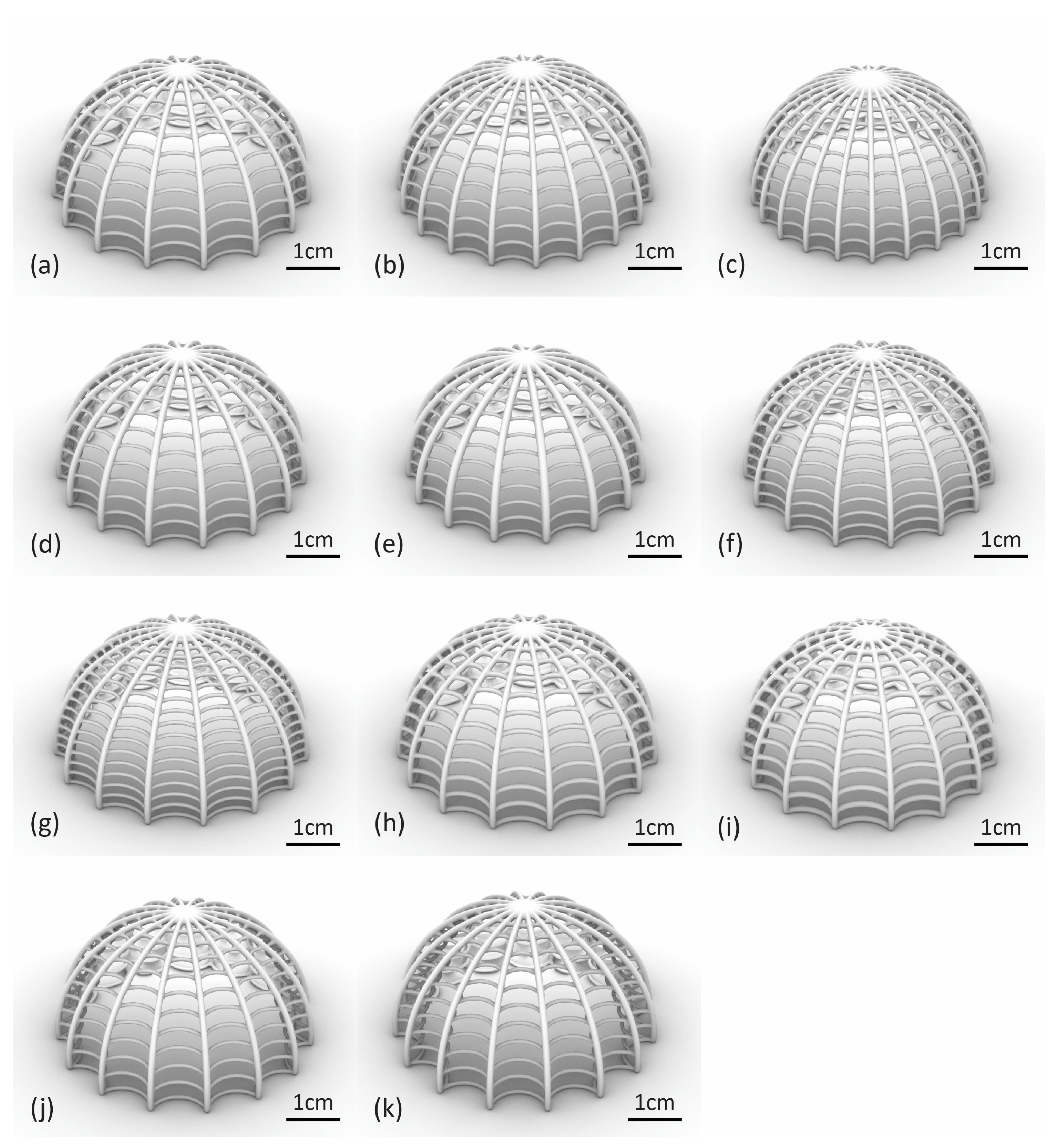
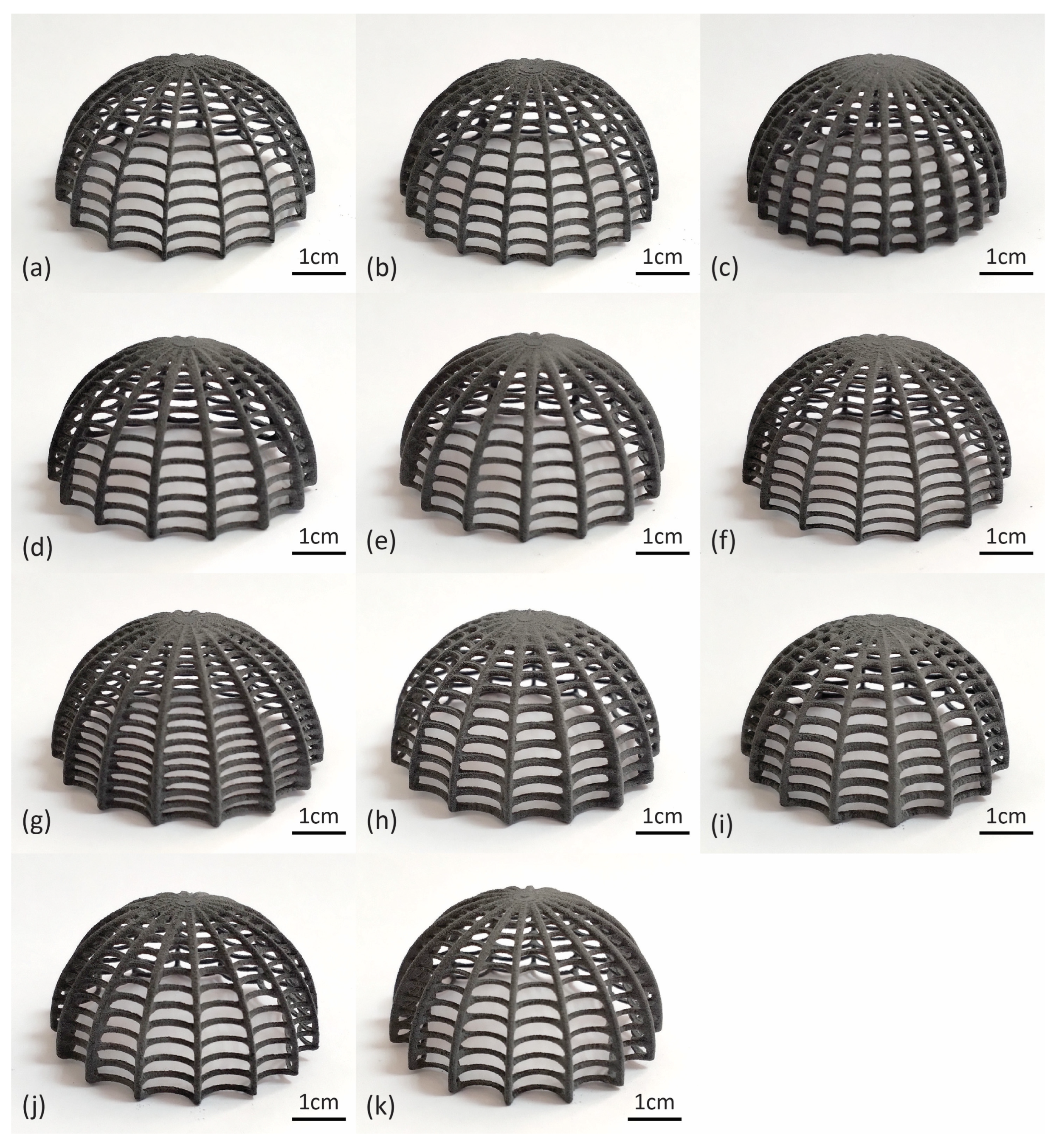
4.1. Algorithmic Design and SLS Printing Results

The result of the above algorithm is a parametric ribbed dome model with a series of user-defined design parameters. Parameters that produce significant changes in the structure’s geometry are the number of ribs and rings, their respective thicknesses, and the curvature of the ring members. A baseline model (Model 1) was generated with design parameter values analogous to the geometrical properties of the original biological structure in order to obtain a model qualitatively similar to the one shown in Figure 2b,c. The baseline biomimetic ribbed dome has a height of 25 mm, a span of 50 mm, and a 90° angle φ. It is also characterized by a rib count of 16, a ring count of 12, a rib and ring radius of 0.4 and 0.6, respectively, and a ring member curvature angle of −30° (angle of the tangent vector of the SED arc). The voxel size, bandwidth, isovalue, and adaptivity parameters were set as 0.2, 8, 0, and 0, respectively. Finally, the values of smooth width, type, and iterations are 1, mean, and 1, respectively. The complete set of design parameters of the baseline model are listed in Table 1.
Variations in the baseline model were created with progressive alterations of its geometric characteristics. For Model 2, the rib count was changed to 20, and for Model 3 to 24. The rib radius in Model 4 was raised to 0.7 mm, and the rib radius of Model 5 to 0.8 mm. Similarly, the ring count of Model 6 was increased to 15 and for Model 7 to 18. The ring radius was raised to 0.5 mm and 0.6 mm for Models 8 and 9, respectively. Lastly, the ring member curvature angle was changed to −15° for Model 10 and to 0° for Model 11. The complete sets of altered parameters can be found in Table 2, and all the corresponding digital models in Figure 8.
Physical samples of each design variation were printed on the SLS platform and can be seen in Figure 9. As for the printing parameters, a layer height of 0.125 mm was selected. The laser power ratio was maintained at 1.00, and the Print Surface Temperature Offset at 0 °C. The shrink ratio was also left unchanged at 1.000 × 1.000 × 1.000. In each print, 8–9 specimens were placed simultaneously to save time, resulting in a total of four prints for the 33 total physical specimens requested. The total print time was, on average, 13 h and 50 min. The required volume of the polyamide powder (power needed in the feed bed) was estimated at 3.82 L on average, and the volume of the refresh powder after print was estimated at 0.86 L (avg). The total feed bed powder height was estimated at 9.6 cm (avg). All the printer parameters can be found in Table 3.

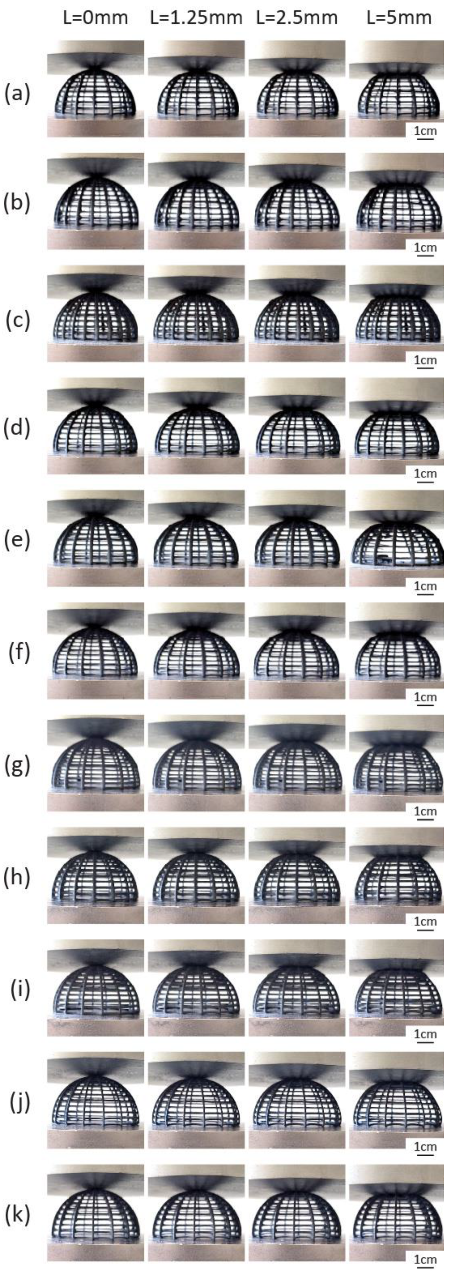
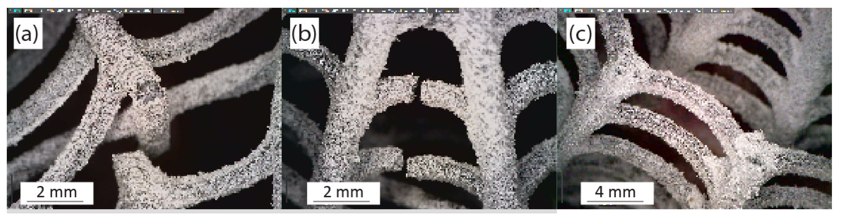
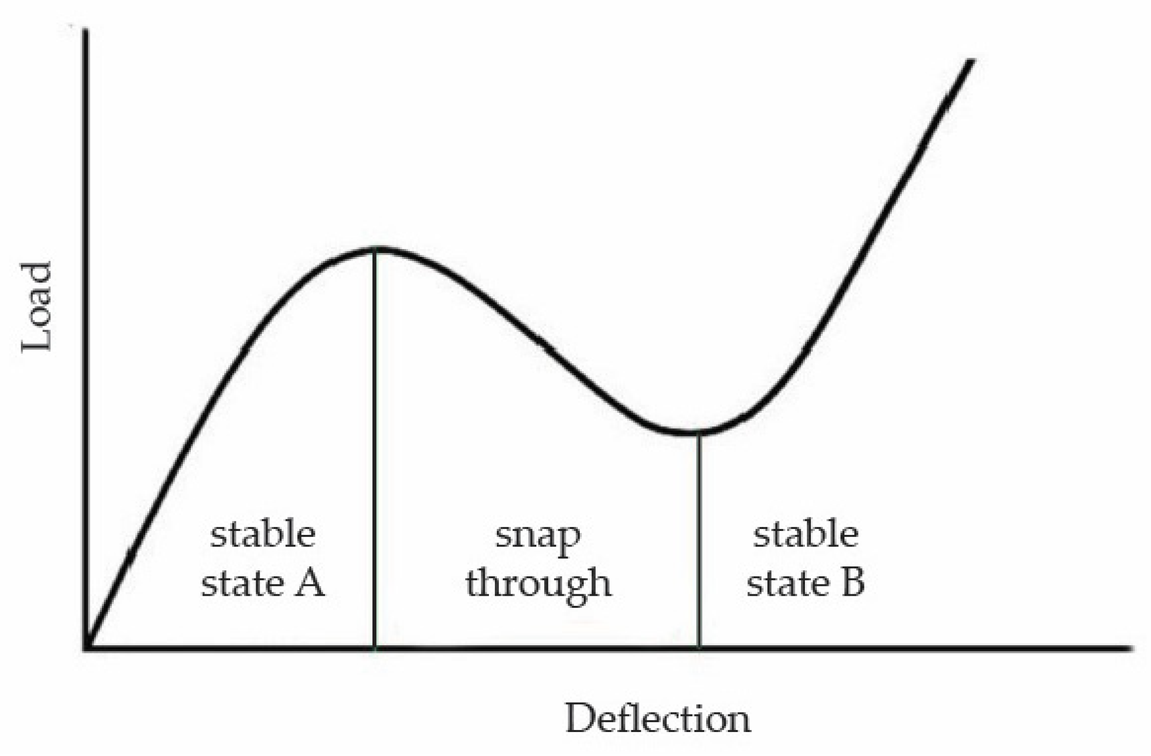
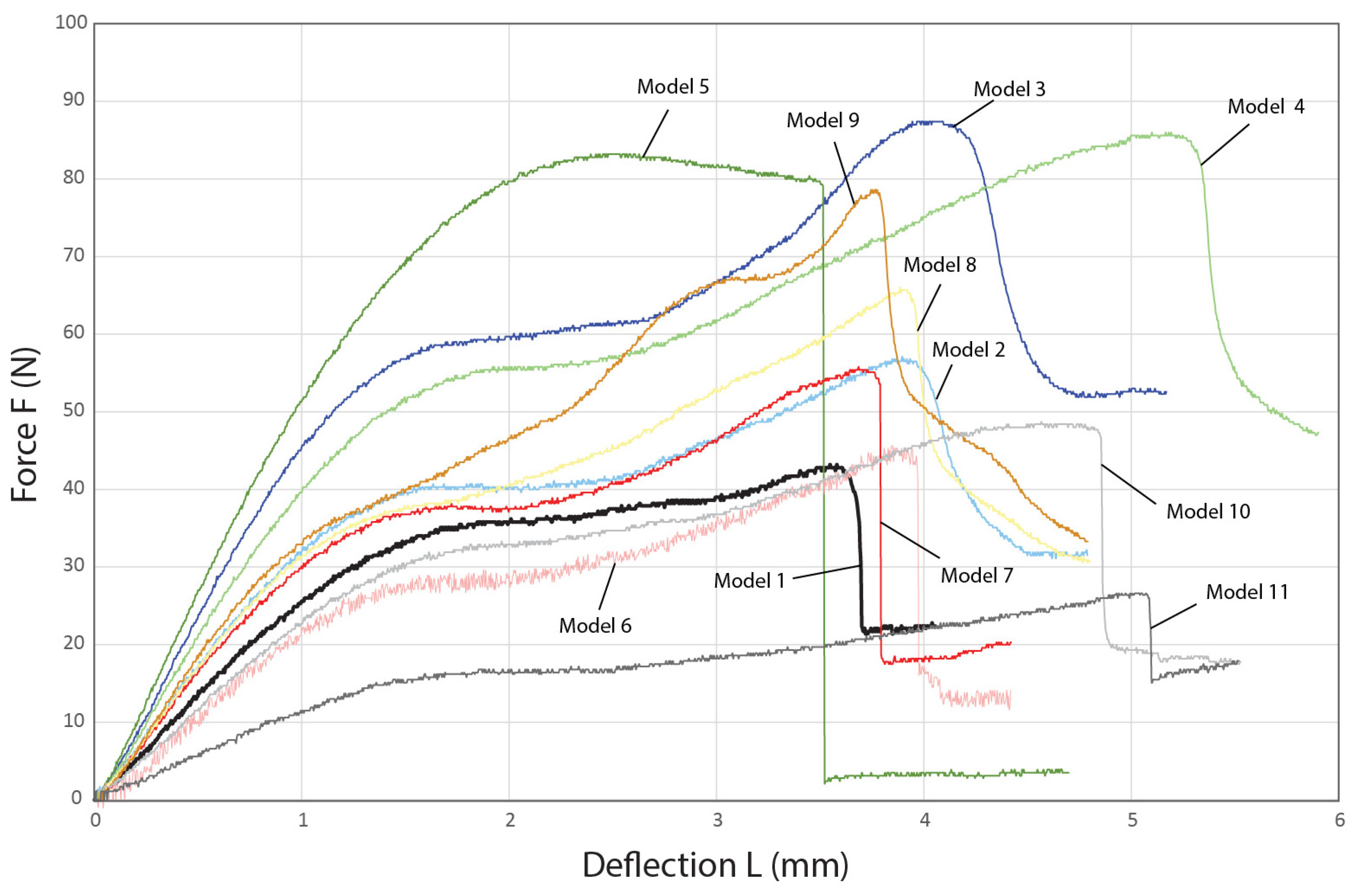
4.2. Characterization of the Compressive Behavior of the 3D-Printed Biomimetic Ribbed Dome Structure

Compression testing of the biomimetic ribbed dome structure reveals a minor snap-through (buckling) behavior that is typical in both solid and lattice domes [56,57]. During this response, a sudden transition occurs in the structure of the dome when a critical load is reached, which can be attributed to node (the joining point of members) instability as certain nodes sustain larger deflections than adjacent nodes due to higher localized stress [52,58,59]. As a result, the nodes collapse to a secondary equilibrium state upon reaching a critical displacement, which is typically characterized by a reverse curvature [60,61]. This behavior can be observed in the second column of the compression frames found in Figure 10, where the onset of the snap-through event occurs at the top of the dome, where the nodes snap and collapse below the compression level. As the event is not very pronounced, it is slightly obscured by the loading element. Subsequently, the structure continues to buckle until it reaches peak load, and the ultimate failure of the dome ensues, as seen in the final frames of Figure 10. Other failure mechanisms involve buckling and fracturing of individual rib or ring members, as seen in Figure 11a,b or total collapse of nodes along a ring, as seen in Figure 11c [52,59,62].
A typical snap-through response curve of solid or lattice domes is illustrated in Figure 12, which is characterized by stark changes in the curve’s slope as the structure moves from stable state A to stable state B, indicating an intense snap-through phenomenon [63,64]. Furthermore, the respective load-deflection curves of the biomimetic ribbed domed specimens can be found in Figure 13. It becomes obvious that the snap-through is significantly dampened in all the tested specimens when compared to the typical curve in Figure 12. Avoiding an intense response of this kind is desirable as the dynamic loads that are developed in the process can prove detrimental to the overall structure [52]. The catastrophic collapse of Model 5 during the snap-through could be regarded as the result of such a mechanism. Thus, raising the rib radius above 0.7 mm would not improve the mechanical performance of the dome as the ensuing aggressive loads during the snap-through phase would lead to the abrupt failure of the dome. The dampening effect of this mechanism observed in the biomimetic structure can be attributed to the biomimetic arachnoid structure and, more specifically, to the concave transverse ring members, which distinguishes the model from a standard lattice dome, as increasing their curvature appears to further reduce the effect as seen in the curves of Models 10 and 11. The design solution abstracted from the eggs of the nymphalid Melitaea sp. efficiently tackles this particular behavior of a ribbed dome when it sustains concentrated compressive loads that could otherwise be disastrous to its structural integrity.
The maximum sustained load of the baseline model (Model 1) is 42.1 ± 2.44 N, as seen in Table 4. When the longitudinal rib count is raised to 20 in Model 2 and 24 in Model 3, the developed max sustained loads increase to 58.33 ± 1.5 N and 87.77 ± 2.27 N, respectively. Increasing the rib radius to 0.7 mm in Model 4 also increases the max load to 87.2 ± 2.27 N. However, when the radius is set to 0.8 mm in Model 5, the highest calculated load drops to 83.03 ± 5.05. As mentioned earlier, increasing the rib radius after a certain point apparently exacerbates the snap-through response, thus creating dynamic loads leading to an early structural failure. Model 6, which is characterized by a ring count of 15, sustains 45.27 ± 2.32 N of maximum compressive load, an increase compared to the baseline. The max load is further enhanced to 51.47 ± 6.97 N when the transverse rings are set to 18 in Model 7. A similar trend is observed when progressively changing the thickness of the rings to 0.5 mm in Model 8 and to 0.6 mm in Model 9. The highest developed loads are determined to be 66.47 ± 6.31 and 76.87 ± 11.1 N, respectively. Finally, increasing the curvature of the ring members, more specifically changing the angle of the tangent vector of the SED arc to −15°, raises the max load to 47.1 ± 2.19 N. However, further altering the angle to 0° decreases the calculated max load to 26.6 ± 1.4 N, which is significantly lower than even the one observed in Model 1. It becomes apparent that even though the biomimetic design solution of the concave ring members effectively deals with the snap-through behavior, there is a certain limitation to increasing the curvature without compromising the overall strength of the dome.

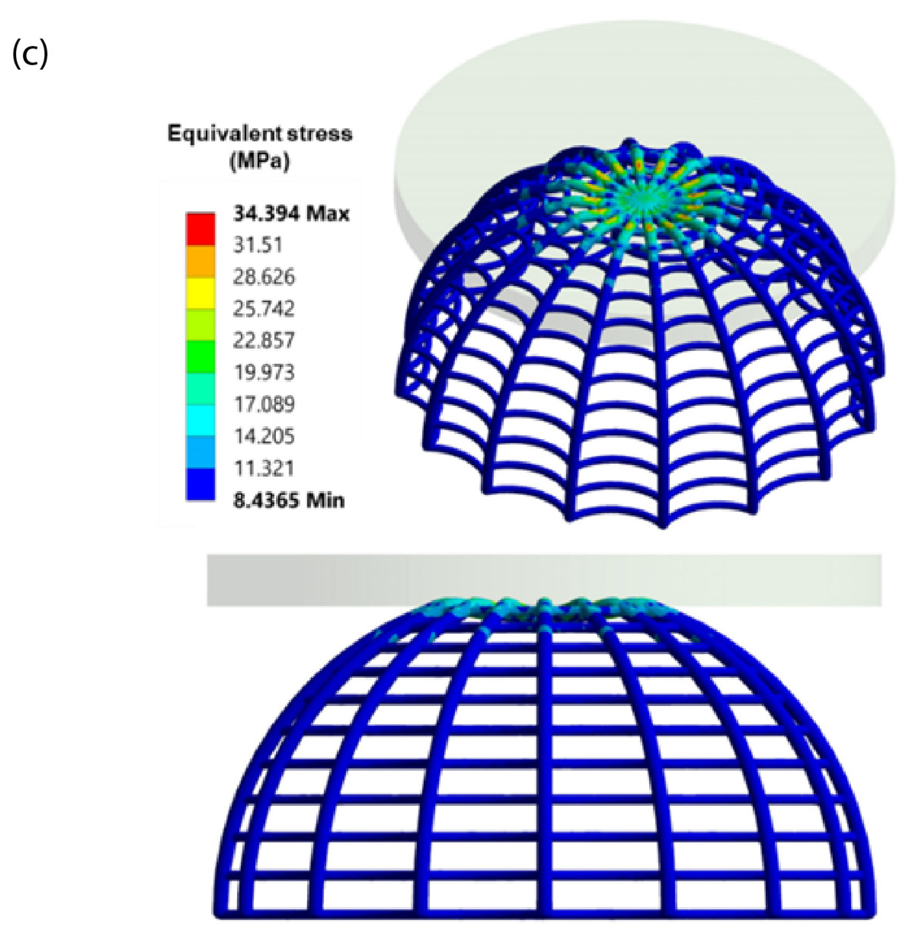
4.3. FEA Validation of Experimental Results

A confirmed material model derived from a numerical-experimental nanoindentation method [65] within the finite element analysis (FEA) was incorporated into the FE model to evaluate how the biomimetic structures perform under compression. Additionally, a computational model was employed to assess how 3D-printed structures respond to compression-induced stress. The biomimetic structures underwent incremental vertical velocities applied to the top plate, while the corresponding reaction forces were recorded at the simple support bottom boundary. The real vertical displacement values were determined from experimental outcomes and imported into the FE model.
Tetrahedral elements were used for the ribs of the domes, while hexahedral elements were employed for meshing the upper compression plate. Figure 14a illustrates the stress–strain behavior acquired through finite element analysis (FEA) for the baseline and the stiffer model, i.e., Model 5. Model 1 serves as the baseline with a certain stress level, and in Model 3, which is characterized by a higher longitudinal rib count, the stiffness and the stress further increase. In contrast, Model 5, featuring a specific rib radius, experiences a notable change in stress and stiffness. This phenomenon emphasizes the influence of rib radius adjustments on structural performance. Consequently, the outcomes displayed in Figure 14b,c, depicting deformation and equivalent stress distribution for the 3D-printed biomimetic structures under compressive load, accurately pinpoint regions with high stress within the structures.
In contrast to prior investigations [65,66,67,68,69,70,71,72,73], lattice structures similar to our present study showcased enhanced physical and mechanical attributes, particularly in terms of significantly improved compressive strength and energy absorption. Conclusions drawn from mechanical test results indicate that combining computationally generated (FEA) compression test data with actual measurements could be an efficient approach for characterizing the mechanical deformation behavior of 3D printed biomimetic configurations.

5. Conclusions

Microscopic analysis of the shell of the eggs of lepidoptera Melitaea sp. ova reveals a ribbed dome which in its middle zone consists of longitudinal ridges and transverse rings composed of concave segments. The transfer of the above structure into a digital model was performed using the software Rhinoceros 3D (v.Rhino 7, 7.1.20343.09491) and Grasshopper 3D (v.1.0.0007). A parametric algorithm was designed, analogous to the biological structure, which allows the adjustment of a number of geometric parameters, such as the number and thickness of the rings and rings, as well as the curvature of the concave transverse segments. A total of 11 design variations were created and physical specimens of the models were fabricated using SLS 3D printing technology and polyamide 12 (nylon) powder.
The physical specimens of the biomimetic ribbed dome were subjected to technical compression tests, which reveal a significant attenuation of the snap-through effect that generally characterizes dome behavior under compressive load. The avoidance of this behavior is desirable as it is accompanied by intense dynamic loads that can lead to catastrophic collapse and can be attributed to the biomimetic design solution of the concave transverse ring sections. Enhancing the curvature of the ring segments significantly reduces the snap-through phenomenon and improves the strength of the structure up to a certain point since considerable weakening of the dome is observed when the curvature is increased more than 0° of the angle of the tangent vector of the SED arc. The maximum load also increases as the number and thickness of the transverse rings and the number of the longitudinal ribs increase. However, raising the radius of the ribs has a positive effect on the overall strength only up to a certain point, as when it reaches a value of 0.8 mm, the snap-through response is aggravated, resulting in premature failure of the structure. Clearly, there is a trade-off between the overall compressive load resistance of the structure and the intensity of the snap-through behavior, expressed geometrically through the above parameters. Moreover, a computational model was utilized to evaluate the response of 3D printed structures to stress induced by compression. The lattice structures demonstrated heightened physical and mechanical characteristics, notably showing substantial enhancements in both compressive strength and energy absorption. This approach is deemed efficient in characterizing the mechanical response of such structures. Future research could focus on further developing the case studies conducted in this research with a view to applying them to specific design issues. The design solution of ribbed domes with concave ring sections, could find application in architectural-scale vaulted structures and in vaulted vessels where it is important to avoid sudden loss of structural integrity.

Author Contributions

Conceptualization, A.E. and I.S.; methodology, A.E., I.S., D.A. and D.T.; software, A.E., I.S. and K.T.; investigation, A.E., D.A. and E.K.T.; visualization, A.E.; writing—original draft preparation, A.E. and K.T.; supervision, I.S. and D.T.; funding acquisition, A.E.; validation, E.K.T.; formal analysis, A.E. and E.K.T.; data curation, A.E., E.K.T. and K.T.; writing—review and editing, I.S. and D.T.; project administration, I.S. All authors have read and agreed to the published version of the manuscript.

Funding

The research was conducted in the operating framework of the Center of Research Innovation and Excellence of the University of Thessaly (Invitation to submit applications for the grant of scholarships to doctoral candidates of the University of Thessaly) and was funded by the Special Account of Research Grants of the University of Thessaly.

Institutional Review Board Statement

Not applicable.

Data Availability Statement

The raw data supporting the conclusions of this article will be made available by the authors on request.

Conflicts of Interest

The authors declare no conflicts of interest.

References

  1. Benyus, J.M. Biomimicry: Innovation Inspired by Nature; Harper Perennial: New York, NY, USA, 2002. [Google Scholar]
  2. Nagel, J.K.S.; Stone, R.B.; McAdams, D.A. An Engineering-to-Biology Thesaurus for Engineering Design. In Proceedings of the 22nd International Conference on Design Theory and Methodology; Special Conference on Mechanical Vibration and Noise, Montreal, QC, Canada, 15–18 August 2010; ASME: New York, NY, USA, 2010; Volume 5, pp. 117–128. [Google Scholar] [CrossRef]
  3. Hooker, G.; Smith, E. Asknature and the biomimicry taxonomy. Insight 2016, 19, 46–49. [Google Scholar] [CrossRef]
  4. The Biomimicry Institute. The Power of the Biomimicry Design Spiral. Biomimicry Institute. 14 June 2016. Available online: https://biomimicry.org/biomimicry-design-spiral/ (accessed on 3 October 2021).
  5. Symeonidou, Ι.; Efstathiadis, A. Biomimetic principles for energy efficiency in buildings. In Proceedings of the 8th International Conference on ENERGY in BUILDINGS 2019, Athens, Greece, 28 September 2019; pp. 33–42. [Google Scholar]
  6. Knippers, J.; Speck, T. Design and construction principles in nature and architecture. Bioinspir. Biomim. 2012, 7, 015002. [Google Scholar] [CrossRef] [PubMed]
  7. Knippers, J.; Nickel, K.G.; Speck, T. (Eds.) Biomimetic Research for Architecture and Building Construction: Biological Design and Integrative Structures. In Biologically-Inspired Systems, 1st ed.; No. 8; Springer International Publishing: Cham, Switzerland; Imprint: Tokyo, Japan, 2016. [Google Scholar] [CrossRef]
  8. Magna, R.L.; Gabler, M.; Reichert, S.; Schwinn, T.; Waimer, F.; Menges, A.; Knippers, J. From Nature to Fabrication: Biomimetic Design Principles for the Production of Complex Spatial Structures. Int. J. Space Struct. 2013, 28, 27–39. [Google Scholar] [CrossRef]
  9. Aish, R.; Woodbury, R. Multi-level Interaction in Parametric Design. In Smart Graphics; Butz, A., Fisher, B., Krüger, A., Olivier, P., Eds.; Lecture Notes in Computer Science; Springer: Berlin/Heidelberg, Germany, 2005; Volume 3638, pp. 151–162. [Google Scholar] [CrossRef]
  10. Bertacchini, F.; Bilotta, E.; Demarco, F.; Pantano, P.; Scuro, C. Multi-objective optimization and rapid prototyping for jewelry industry: Methodologies and case studies. Int. J. Adv. Manuf. Technol. 2021, 112, 2943–2959. [Google Scholar] [CrossRef]
  11. Nordin, A.; Hopf, A.; Motte, D. Generative Design Systems for the Industrial Design of Functional Mass Producible Natural-Mathematical Forms. In Proceedings of the 5th International Congress of International Association of Societies of Design Research-IASDR’13, Tokyo, Japan, 26–30 August 2013; pp. 2931–2941. [Google Scholar]
  12. Knippers, J.; Kropp, C.; Menges, A.; Sawodny, O.; Weiskopf, D. Integrative computational design and construction: Rethinking architecture digitally. Civ. Eng. Des. 2021, 3, 123–135. [Google Scholar] [CrossRef]
  13. Eckert, C.; Kelly, I.; Stacey, M. Interactive generative systems for conceptual design: An empirical perspective. Artif. Intell. Eng. Des. Anal. Manuf. 1999, 13, 303–320. [Google Scholar] [CrossRef]
  14. Bates, S.R.G.; Farrow, I.R.; Trask, R.S. 3D printed polyurethane honeycombs for repeated tailored energy absorption. Mater. Des. 2016, 112, 172–183. [Google Scholar] [CrossRef]
  15. Yang, Y.; Song, X.; Li, X.; Chen, Z.; Zhou, C.; Zhou, Q.; Chen, Y. Recent Progress in Biomimetic Additive Manufacturing Technology: From Materials to Functional Structures. Adv. Mater. 2018, 30, 1706539. [Google Scholar] [CrossRef]
  16. Zhang, L.; Liu, H.; Yao, H.; Zeng, Y.; Chen, J. 3D Printing of Hollow Lattice Structures of ZrO2(3Y)/Al2O3 Ceramics by Vat Photopolymerization: Process Optimization, Microstructure Evolution and Mechanical Properties. J. Manuf. Process. 2022, 83, 756–767. [Google Scholar] [CrossRef]
  17. Razaviye, M.K.; Tafti, R.A.; Khajehmohammadi, M. An investigation on mechanical properties of PA12 parts produced by a SLS 3D printer: An experimental approach. CIRP J. Manuf. Sci. Technol. 2022, 38, 760–768. [Google Scholar] [CrossRef]
  18. Goodridge, R.D.; Tuck, C.J.; Hague, R.J.M. Laser sintering of polyamides and other polymers. Prog. Mater. Sci. 2012, 57, 229–267. [Google Scholar] [CrossRef]
  19. Tofail, S.A.M.; Koumoulos, E.P.; Bandyopadhyay, A.; Bose, S.; O’Donoghue, L.; Charitidis, C. Additive manufacturing: Scientific and technological challenges, market uptake and opportunities. Mater. Today 2018, 21, 22–37. [Google Scholar] [CrossRef]
  20. Szymczyk-Ziółkowska, P.; Łabowska, M.B.; Detyna, J.; Michalak, I.; Gruber, P. A review of fabrication polymer scaffolds for biomedical applications using additive manufacturing techniques. Biocybern. Biomed. Eng. 2020, 40, 624–638. [Google Scholar] [CrossRef]
  21. Wang, Y.; Xu, Z.; Wu, D.; Bai, J. Current Status and Prospects of Polymer Powder 3D Printing Technologies. Materials 2020, 13, 2406. [Google Scholar] [CrossRef] [PubMed]
  22. Ngo, T.D.; Kashani, A.; Imbalzano, G.; Nguyen, K.T.Q.; Hui, D. Additive manufacturing (3D printing): A review of materials, methods, applications and challenges. Compos. Part B Eng. 2018, 143, 172–196. [Google Scholar] [CrossRef]
  23. Xu, Z.; Wang, Y.; Wu, D.; Ananth, K.P.; Bai, J. The process and performance comparison of polyamide 12 manufactured by multi jet fusion and selective laser sintering. J. Manuf. Process. 2019, 47, 419–426. [Google Scholar] [CrossRef]
  24. Cobian, L.; Rueda-Ruiz, M.; Fernandez-Blazquez, J.; Martinez, V.; Galvez, F.; Karayagiz, F.; Lück, T.; Segurado, J.; Monclus, M. Micromechanical characterization of the material response in a PA12-SLS fabricated lattice structure and its correlation with bulk behavior. Polym. Test. 2022, 110, 107556. [Google Scholar] [CrossRef]
  25. Munir, K.S.; Li, Y.; Wen, C. Metallic scaffolds manufactured by selective laser melting for biomedical applications. In Metallic Foam Bone; Elsevier: Amsterdam, The Netherlands, 2017; pp. 1–23. [Google Scholar] [CrossRef]
  26. Freeman, C.L.; Harding, J.H.; Quigley, D.; Rodger, P.M. Structural Control of Crystal Nuclei by an Eggshell Protein. Angew. Chem. Int. Ed. 2010, 49, 5135–5137. [Google Scholar] [CrossRef] [PubMed]
  27. Rezende, G.L.; Vargas, H.C.M.; Moussian, B.; Cohen, E. Composite Eggshell Matrices: Chorionic Layers and Sub-chorionic Cuticular Envelopes. In Extracellular Composite Matrices in Arthropods; Cohen, E., Moussian, B., Eds.; Springer International Publishing: Cham, Switzerland, 2016; pp. 325–366. [Google Scholar] [CrossRef]
  28. Nys, Y.; Gautron, J.; Garcia-Ruiz, J.M.; Hincke, M.T. Avian eggshell mineralization: Biochemical and functional characterization of matrix proteins. C. R. Palevol 2004, 3, 549–562. [Google Scholar] [CrossRef]
  29. Sidorov, A.V.; Kolesnichenko, K.A.; Sviridov, A.V. Features of the Chorion Egg Structure in Nine Species of Underwing Moths Belonging to the Genus Catocala (Lepidoptera, Erebidae). Entomol. Rev. 2019, 99, 615–620. [Google Scholar] [CrossRef]
  30. Legendre, L.J.; Choi, S.; Clarke, J.A. The diverse terminology of reptile eggshell microstructure and its effect on phylogenetic comparative analyses. J. Anat. 2022, 241, 641–666. [Google Scholar] [CrossRef] [PubMed]
  31. Srivastava, A.K.; Kumar, K. Ultrastructure of egg chorion of castor butterfly Ariadne merione (Crammer) (Lepidoptera: Nymphalidae). Zool. Anz.-J. Comp. Zool. 2016, 263, 1–5. [Google Scholar] [CrossRef]
  32. Cônsoli, F.L.; Kitajima, E.W.; Parra, J.R.P. Ultrastructure of the natural and factitious host eggs of Trichogramma galloi Zucchi and Trichogramma pretiosum Riley (Hymenoptera: Trichogrammatidae). Int. J. Insect Morphol. Embryol. 1999, 28, 211–231. [Google Scholar] [CrossRef]
  33. Bigatti, G.; Giraud-Billoud, M.; Vega, I.A.; Penchaszadeh, P.E.; Castro-Vazquez, A. The calcareous egg capsule of the Patagonian neogastropod Odontocymbiola magellanica: Morphology, secretion and mineralogy. J. Molluscan Stud. 2010, 76, 279–288. [Google Scholar] [CrossRef]
  34. Nieves-Uribe, S.; Flores-Gallardo, A.; Llorente-Bousquets, J. Chorion exploration in the tribe Anthocharidini (Lepidoptera: Pieridae) and their possible importance in its systematics. Zootaxa 2020, 4868, 151–207. [Google Scholar] [CrossRef]
  35. Williams, M. Chapter 2. Scientific Aspects of Lepidopterology. In Practical Guide to the Study of Lepidoptera in Africa; Lepidopterist’s Society of Africa: Cascades, South Africa, 2015; 18p. [Google Scholar]
  36. Hincke, T.M. The eggshell: Structure, composition and mineralization. Front. Biosci. 2012, 17, 1266. [Google Scholar] [CrossRef]
  37. Hahn, E.N.; Sherman, V.R.; Pissarenko, A.; Rohrbach, S.D.; Fernandes, D.J.; Meyers, M.A. Nature’s technical ceramic: The avian eggshell. J. R. Soc. Interface 2017, 14, 20160804. [Google Scholar] [CrossRef]
  38. Efstathiadis, A.; Symeonidou, I. Developing Strategies for the Analysis and Implementation of Biomimetic Design Solutions. Presented at the eCAADe 2023: Digital Design Reconsidered, Graz, Austria, 20–22 September 2023; pp. 87–94. [Google Scholar] [CrossRef]
  39. Efstathiadis, A.; Symeonidou, I.; Tsongas, K.; Tzimtzimis, E.K.; Tzetzis, D. Parametric Design and Mechanical Characterization of 3D-Printed PLA Composite Biomimetic Voronoi Lattices Inspired by the Stereom of Sea Urchins. J. Compos. Sci. 2022, 7, 3. [Google Scholar] [CrossRef]
  40. Efstathiadis, A.; Symeonidou, I.; Tsongas, K.; Tzimtzimis, E.K.; Tzetzis, D. 3D Printed Voronoi Structures Inspired by Paracentrotus lividus Shells. Designs 2023, 7, 113. [Google Scholar] [CrossRef]
  41. Symeonidou, I.; Efsthathiadis, A. Digital Biomimicry: Developing an algorithmic design curriculum. Presented at the eCAADe 2023: Digital Design Reconsidered, Graz, Austria, 20–22 September 2023; pp. 109–116. [Google Scholar] [CrossRef]
  42. Efstathiadis, A.; Symeonidou, I. High performance biological structures. In Proceedings of the 4th International Conference for Biodigital Architecture & Genetics, Barcelona, Spain, 6 November 2020; iBAG-UIC Barcelona, Institute for Biological Architecture & Genetics, Universitat Internacional de Catalunya: Barcelona, Spain, 2020; pp. 22–33. [Google Scholar]
  43. García-Barros, E. The eggs of European satyrine butterflies (Nymphalidae): External morphology and its use in systematics. Zool. J. Linn. Soc. 1995, 115, 73–115. [Google Scholar] [CrossRef]
  44. Munguira, M.L.; Martín, J.; García-Barros, E.; Shahbazian, G.; Cancela, J.P. Morphology and morphometry of Lycaenid eggs (Lepidoptera: Lycaenidae). Zootaxa 2015, 3937, 201. [Google Scholar] [CrossRef]
  45. Tolman, T.; Lewington, R. Collins Butterfly Guide, New ed.; Collins: London, UK, 2008. [Google Scholar]
  46. Pamperis, L.N. The Butterflies of Greece; 2. Aufl; Editions Pamperis: Athens, Greece, 2009. [Google Scholar]
  47. Newbury, D.E. (Ed.) Advanced Scanning Electron Microscopy and X-Ray Microanalysis; Plenum Press: New York, NY, USA, 1986. [Google Scholar]
  48. Dendro. Food4Rhino. Available online: https://www.food4rhino.com/app/dendro (accessed on 18 March 2021).
  49. Llorente-Bousquets, J.; Nieves-Uribe, S.; Flores-Gallardo, A.; Hernández-Mejía, B.C.; Castro-Gerardino, J. Chorionic sculpture of eggs in the subfamily Dismorphiinae (Lepidoptera: Papilionoidea: Pieridae). Zootaxa 2018, 4429, 201. [Google Scholar] [CrossRef]
  50. Nieves-Uribe, S.; Llorente-Bousquets, J.; Flores-Gallardo, A. Micropylar and Perimicropylar Regions of the Egg Exochorion in Six Genera of Dismorphiinae (Lepidoptera: Pieridae). Zootaxa 2021, 4966, 251289. [Google Scholar] [CrossRef] [PubMed]
  51. Cheng, L.; Tang, T.; Yang, H.; Hao, F.; Wu, G.; Lyu, F.; Bu, Y.; Zhao, Y.; Zhao, Y.; Liu, G.; et al. The Twisting of Dome-Like Metamaterial from Brittle to Ductile. Adv. Sci. 2021, 8, 2002701. [Google Scholar] [CrossRef]
  52. López, A.; Puente, I.; Serna, M.A. Direct evaluation of the buckling loads of semi-rigidly jointed single-layer latticed domes under symmetric loading. Eng. Struct. 2007, 29, 101–109. [Google Scholar] [CrossRef]
  53. Nayak, C.B.; Jain, M.A.; Walke, S.B. Parametric Study of Dome with and Without Opening. J. Inst. Eng. India Ser. A 2020, 101, 463–475. [Google Scholar] [CrossRef]
  54. Timoshenko, S.; Woinowsky-Krieger, S. Theory of Plates and Shells, 2nd ed.; 13th Reprint; McGraw-Hill Education: New Delhi, India, 2015. [Google Scholar]
  55. Kato, S.; Mutoh, I.; Shomura, M. Collapse of semi-rigidly jointed reticulated domes with initial geometric imperfections. J. Constr. Steel Res. 1998, 48, 145–168. [Google Scholar] [CrossRef]
  56. Cheng, L.; Wang, L.; Karlsson, A.M. Mechanics-based analysis of selected features of the exoskeletal microstructure of Popillia japonica. J. Mater. Res. 2009, 24, 3253–3267. [Google Scholar] [CrossRef]
  57. Easey, N.; Chuprynyuk, D.; Musa, W.M.S.W.; Bangs, A.; Dobah, Y.; Shterenlikht, A.; Scarpa, F. Dome-Shape Auxetic Cellular Metamaterials: Manufacturing, Modeling, and Testing. Front. Mater. 2019, 6, 86. [Google Scholar] [CrossRef]
  58. Leahu-Aluas, I.; Abed-Meraim, F. A proposed set of popular limit-point buckling benchmark problems. Struct. Eng. Mech. 2011, 38, 767–802. [Google Scholar] [CrossRef]
  59. Gioncu, V. Buckling of Reticulated Shells: State-of-the-Art. Int. J. Space Struct. 1995, 10, 1–46. [Google Scholar] [CrossRef]
  60. Plaut, R.H. Snap-through of shallow reticulated domes under unilateral displacement control. Int. J. Solids Struct. 2018, 148–149, 24–34. [Google Scholar] [CrossRef]
  61. Plaut, R.H. Snap-through of arches and buckled beams under unilateral displacement control. Int. J. Solids Struct. 2015, 63, 109–113. [Google Scholar] [CrossRef]
  62. Fan, F.; Yan, J.; Cao, Z. Stability of reticulated shells considering member buckling. J. Constr. Steel Res. 2012, 77, 32–42. [Google Scholar] [CrossRef]
  63. Li, Y.; Xu, Y.L. Tuning and switching of band gap of the periodically undulated beam by the snap through buckling. AIP Adv. 2017, 7, 055210. [Google Scholar] [CrossRef]
  64. Hu, N.; Burgueño, R. Buckling-induced smart applications: Recent advances and trends. Smart Mater. Struct. 2015, 24, 063001. [Google Scholar] [CrossRef]
  65. Giarmas, E.; Tsongas, K.; Tzimtzimis, E.K.; Korlos, A.; Tzetzis, D. Mechanical and FEA-Assisted Characterization of 3D Printed Continuous Glass Fiber Reinforced Nylon Cellular Structures. J. Compos. Sci. 2021, 5, 313. [Google Scholar] [CrossRef]
  66. Kladovasilakis, N.; Tsongas, K.; Kostavelis, I.; Tzovaras, D.; Tzetzis, D. Effective Mechanical Properties of Additive Manufactured Strut-Lattice Structures: Experimental and Finite Element Study. Adv. Eng. Mater. 2022, 24, 2100879. [Google Scholar] [CrossRef]
  67. Kladovasilakis, N.; Tsongas, K.; Kostavelis, I.; Tzovaras, D.; Tzetzis, D. Effective mechanical properties of additive manufactured triply periodic minimal surfaces: Experimental and finite element study. Int. J. Adv. Manuf. Technol. 2022, 121, 7169–7189. [Google Scholar] [CrossRef]
  68. Zoumaki, M.; Mansour, M.T.; Tsongas, K.; Tzetzis, D.; Mansour, G. Mechanical Characterization and Finite Element Analysis of Hierarchical Sandwich Structures with PLA 3D-Printed Core and Composite Maize Starch Biodegradable Skins. J. Compos. Sci. 2022, 6, 118. [Google Scholar] [CrossRef]
  69. Kladovasilakis, N.; Tsongas, K.; Tzetzis, D. Finite Element Analysis of Orthopedic Hip Implant with Functionally Graded Bioinspired Lattice Structures. Biomimetics 2020, 5, 44. [Google Scholar] [CrossRef] [PubMed]
  70. Kladovasilakis, N.; Charalampous, P.; Boumpakis, A.; Kontodina, T.; Tsongas, K.; Tzetzis, D.; Kostavelis, I.; Givissis, P.; Tzovaras, D. Development of biodegradable customized tibial scaffold with advanced architected materials utilizing additive manufacturing. J. Mech. Behav. Biomed. Mater. 2023, 141, 105796. [Google Scholar] [CrossRef] [PubMed]
  71. Mansour, M.T.; Tsongas, K.; Tzetzis, D. Carbon-Fiber- and Nanodiamond-Reinforced PLA Hierarchical 3D-Printed Core Sandwich Structures. J. Compos. Sci. 2023, 7, 285. [Google Scholar] [CrossRef]
  72. Kladovasilakis, N.; Tsongas, K.; Karalekas, D.; Tzetzis, D. Architected Materials for Additive Manufacturing: A Comprehensive Review. Materials 2022, 15, 5919. [Google Scholar] [CrossRef] [PubMed]
  73. Mansour, M.T.; Tsongas, K.; Tzetzis, D. 3D Printed Hierarchical Honeycombs with Carbon Fiber and Carbon Nanotube Reinforced Acrylonitrile Butadiene Styrene. J. Compos. Sci. 2021, 5, 62. [Google Scholar] [CrossRef]
Figure 1. The novel biomimetic design strategy is characterized by by-directional feedback loops between its three stages: the “Research and Analysis” stage, followed by the “Abstraction and Emulation” stage, and concluded with the “Technical Evaluation” stage.
Biomimetics 10 00001 g001
Figure 2. Imaging of the eggs of Melitaea sp.: (a) the eggs under optical microscopy as seen deposited on a leaf; (b) a single egg under SEM with its three zones—apical, medial, and basal—visible; (c) close-up of the medial zone where the longitudinal ribs and transversal rings form an arachnoid grip pattern.
Biomimetics 10 00001 g002
Figure 3. Main geometric characteristics of a dome: (a) longitudinal ribs (n) and transverse rings (a); (b) height (H), its span (D), and the total subtended angle (φ).
Biomimetics 10 00001 g003
Figure 4. Longitudinal cross-section of a ribbed dome with ring member angle φ/α and rib member angle 2θ0.
Biomimetics 10 00001 g004
Figure 5. The interactive algorithm in the Grasshopper environment.
Biomimetics 10 00001 g005
Figure 6. Top-level workflow diagram of the design algorithm of the biomimetic ribbed dome. Important parameters are seen in light gray boxes.
Biomimetics 10 00001 g006
Figure 7. Second-level workflow diagram of the algorithmic generation of the biomimetic dome. Dependent parameters are in white and independent ones in light gray boxes.
Biomimetics 10 00001 g007
Figure 8. Digital models of the biomimetic dome structure: (a) Model 1 (baseline); (b) Model 2; (c) Model 3; (d) Model 4; (e) Model 5; (f) Model 6; (g) Model 7; (h) Model 8; (i) Model 9; (j) Model 10; (k) Model 11.
Biomimetics 10 00001 g008
Figure 9. Three-dimensionally printed specimens of the biomimetic dome structure: (a) Model 1 (baseline); (b) Model 2; (c) Model 3; (d) Model 4; (e) Model 5; (f) Model 6; (g) Model 7; (h) Model 8; (i) Model 9; (j) Model 10; (k) Model 11.
Biomimetics 10 00001 g009
Figure 10. Compressive behavior at 0 mm, 1.25 mm, 2.5 mm, and 5 mm of (a) Model 1 (baseline); (b) Model 2; (c) Model 3; (d) Model 4; (e) Model 5; (f) Model 6; (g) Model 7; (h) Model 8; (i) Model 9; (j) Model 10 and (k) Model 11.
Biomimetics 10 00001 g010
Figure 11. Failure points of the ribbed dome: (a) buckling and fracture of individual rib members; (b) buckling and fracture of individual ring members; (c) line instability, where a whole ring collapses.
Biomimetics 10 00001 g011
Figure 12. A typical curve of the snap-through response is observed in a solid or regular ribbed dome under compressive load.
Biomimetics 10 00001 g012
Figure 13. Load–deflection curves of the 3D-printed biomimetic domes when tested under compressive load.
Biomimetics 10 00001 g013
Figure 14. (a) The stress–strain behavior of the biomimetic lattice structures generated by finite element analysis (FEA), (b) vertical deformation, and (c) stress distribution of the biomimetic structure under compression load were analyzed using the material properties of PA12 within the FE model.
Biomimetics 10 00001 g014aBiomimetics 10 00001 g014b
Table 1. The complete design parameters of the baseline (Model 1) biomimetic ribbed dome.
Design ParameterValue
Dome Span50 mm
Dome Height25 mm
U count16
V count12
SED angle−30°
Curve Radius (ribs)0.6 mm
Curve Radius (rings)0.4 mm
Voxel Size0.2
Bandwidth8
Isovalue0
Adaptivity0
Smooth Width1
Type2 (mean)
Iterations1
Table 2. Geometric parameters of all biomimetic model permutations.
ModelRib CountRib Radius (mm)Ring CountRing Radius (mm)Ring
Curvature
1160.6120.4−30°
2200.6120.4−30°
3240.6120.4−30°
4160.7120.4−30°
5160.8120.4−30°
6160.6150.4−30°
7160.6180.4−30°
8160.6120.5−30°
9160.6120.6−30°
10160.6120.4−15°
11160.6120.4
Table 3. SLS printer parameters that were used during the printing process of the biomimetic structures.
Printer ParameterValue
Printer ModelLisa rev.A
MaterialPolyamide12 Smooth
Layer Height0.125 mm
Laser Power Ratio1.00
Print Surface Temperature Offset0 °C
Shrink Ratio1.000 × 1.000 × 1.000
Total Print Time (avg)13 h 50 min
Powder Needed in Feed Bed (avg)3.82 L
Refresh Powder After Print (avg)0.86 L
Feed Bed Power Height (avg)9.6 cm
Table 4. Maximum sustained loads of the 3D-printed models according to experimental testing.
ModelLoadmax (N)
142.1 ± 2.44
258.33 ± 1.5
387.77 ± 2.27
487.2 ± 2.34
583.03 ± 5.05
645.27 ± 2.32
751.47 ± 6.97
866.47 ± 6.31
976.87 ± 11.1
1047.1 ± 2.19
1126.6 ± 1.4
Disclaimer/Publisher’s Note: The statements, opinions and data contained in all publications are solely those of the individual author(s) and contributor(s) and not of MDPI and/or the editor(s). MDPI and/or the editor(s) disclaim responsibility for any injury to people or property resulting from any ideas, methods, instructions or products referred to in the content.

