Article

ATEX-HOF Methodology: Innovation Driven by Human and Organizational Factors (HOF) in Explosive Atmosphere Risk Assessment

1
China Institute of Regulation Research, Zhejiang University of Finance and Economics, No. 18, Xueyuan Road, High Education District, Xiasha, Hangzhou 310018, Zhejiang, China
2
ARIA srl, Via Colli 24, 10129 Torino, Italy
3
SAfeR, Dipartimento di Scienza Applicta e Tecnologia, Politecnico di Torino, Corso Duca degli Abruzzi, 24, 10129 Torino, Italy
*
Authors to whom correspondence should be addressed.
Submission received: 2 October 2019 / Revised: 18 December 2019 / Accepted: 8 January 2020 / Published: 21 January 2020

Abstract

:
ATEX (explosive atmosphere) risk assessment is required when any equipment or system could generate a potentially explosive atmosphere. Despite the fact that many operations on plants and equipment containing dangerous substances are performed by operators, influences of human and organizational factors (HOF) are mostly neglected in the ATEX risk assessment. The integrated methodology described here is proposed to address two challenges: (1) identification of the HOF influence on the ATEX risk assessment, and (2) quantification of the HOF influence. The proposed methodology enriches the traditional ATEX risk assessment procedure, which consists of four steps: (1) area classification, (2) ignition source identification, (3) damage analysis, and (4) ATEX risk evaluation. The advantages of the ATEX-HOF methodology are demonstrated through the application to a paint mixing station in an automotive manufacturing plant. The ATEX risk assessment methodologies are mainly semi-quantitative. The ATEX-HOF methodology provides a quantitative analysis for the area classification and ignition source identification, and a semi-quantitative approach for the damage analysis. As a result, the ATEX-HOF risk evaluation becomes more accurate. An event tree-based probabilistic assessment has been introduced, considering both the technical barrier failure (Prtbf) and the human intervention in terms of human error probability (HEP). The case study allowed for demonstrating how taking HOFs into account is particularly important in companies where the safety culture is lower and consequently, the usual hypothesis of the correctness of operator intervention (in maintenance, normal operations, and emergency) could bring to non-conservative results.

1. Introduction

In Europe, the risk of explosive atmosphere has to be evaluated and managed according to the explosive atmosphere (ATEX) directive [1], whenever an equipment or system could generate a potentially explosive atmosphere due to the release of flammable gas or vapors or combustible dust during normal operations or in case of predictable failure.
The risk assessment methodology is used for risk-based decision making in process plants as the hazard identification techniques, such as HazOp and fault tree analysis [2,3,4], or even the decision analysis [5,6,7], are not used for the purpose of ATEX because they are too complex and detailed. For this reason, different ATEX risk assessment methodologies were developed to fulfil the directive requirements. Among others, Markowski [8] proposed the ExLOPA (Explosion Layer of Protection Analysis) methodology, which is based on the original approach of CCPS (Center for Chemical Process Safety) [9] for LOPA (level of protection analysis). Within the European Union (EU) Project RASE (Explosive Atmosphere: Risk Assessment of Unit Operations and Equipment) (2000) “Explosive Atmosphere: Risk Assessment of Unit Operations and Equipment”, a methodology for the risk assessment of unit operations and equipment to be used in potentially explosive atmospheres was proposed. Cavaliere and Scardamaglia [10] and Cavaliere [11] developed a methodology for the ATEX risk assessment that fulfils the requirements of both ATEX Directive 94/9/EC and the related standards. The proposed approach builds on the methodology proposed by Cavaliere, made of four steps: (1) zone classification, (2) ignition source identification, (3) damage analysis, and (4) ATEX risk assessment.
The area classification depends on the probability of the formation of a potentially explosive atmosphere in a given area and on the available barriers to flammable substance persistence in the work environment. Thus, the different pieces of equipment from which a release could occur are considered, e.g., leakage from pipe or fittings connection, together with the operations that could generate a gas or dust emission in the work environment, e.g., emptying bags into hoppers.
Then, the ventilation is considered in terms of effectiveness and availability.
For both the aspects, the effects of the operations, that the plant operators could perform on them as inspection, maintenance, etc., are not explicitly taken into account. This means that any manual operation is considered as correctly carried on.
The possible shortcomings deriving from the human and organizational factors overlooked in the ATEX analysis have been identified during the FP7 Marie Curie ITN InnHF project (Innovation Through Human Factors in risk analysis and management), during which several surveys were submitted to different companies to identify the industrial praxis related to the human factor analysis, the perceived shortcomings related to their omission, and the need for integrated methodologies able to analyze them jointly with the technical aspects. From the surveys, it emerged how the strong influence of the maintenance activities on the operations that could affect the safety of the plants and equipment, including ATEX, could not be correctly represented by the traditional risk assessment methodologies, resulting in an unrealistic risk estimation and related decision making. The problem has not been addressed in other studies before.
This paper will thus present a methodology to explicitly consider the HOF within the ATEX risk assessment. Different techniques are available in the literature to quantitatively assess the human error probabilities. Previous studies from the same authors [12,13] compared the task-dominant approach to the HOF—THERP (the technique for human error rate prediction [14]), and the cognition-dominant approach—CREAM (cognitive reliability and error analysis method [15]), associated to the fuzzy tool for the quantification. The results showed that CREAM with the fuzzy application meets the need for a simple, rapid, but effective tool. In this study, a dedicated tool was developed to apply FUZZY CREAM, based on the cognitive reliability and error analysis method (CREAM) [16]. The method, initially qualitative, was designed for different types of industries. Then, Konstandinidou et al. [16] introduced FUZZY CREAM as a complementary methodology to quantitatively assess human error probability (HEP), further applied as an example in Marseguerra et al. [17] and Monferini et al. [18].
The paper is thus organized as follows: Section 2 is devoted to the description of the integrated methodology developed. The application to the risk assessment of a paint mixing station in an automotive manufacturing plant and the related results are detailed in Section 3. Methodological conclusions are then discussed in Section 4.

2. Materials and Methods

2.1. Fuzzy Cognitive Reliability and Error Analysis Method (CREAM)

The fuzzy CREAM method [16] is used to evaluate the probability of human error on the base of the interactions between person-related, technology-related, and organization-related factors. Formally, a fuzzy set A defined in a universe of discourse X is expressed by its membership function A: X→ [0,1], where the degree of membership A(x) expresses the extent to which x fulfills the category described by A. The condition A(x) = 1 denotes all the elements that are fully compatible with A. The condition A(x) = 0 identifies all elements that definitely do not belong to A.
In fuzzy sets, the meaning of the set theory predicate ‘∈’ (element of) is extended accepting a partial membership in a set. The basic operations can be defined as:
(A∪B) (x) = max(A(x), B(x))
(A∩B) = min(A(x), B(x))
A ¯ ( x ) = 1 A ( x )
where x∈X. A fuzzy model requires that the input variables undergo three major elaborations before an output is obtained: fuzzification, fuzzy inference, and defuzzification. Fuzzification is the process of decomposing system input variables into one or more fuzzy sets. Fuzzy inference consists in the development of a set of if-then-else rules, used to process the inputs and produce a fuzzy output. Each rule consists of a condition and an action where the condition is interpreted from the input fuzzy set and the output is determined on the output fuzzy set. Defuzzification is the process of weighting and averaging the outputs from all the individual fuzzy rules into one single output decision or signal. The output signal eventually exiting the system is a precise, defuzzified, crisp value.
In the FUZZY CREAM methods [
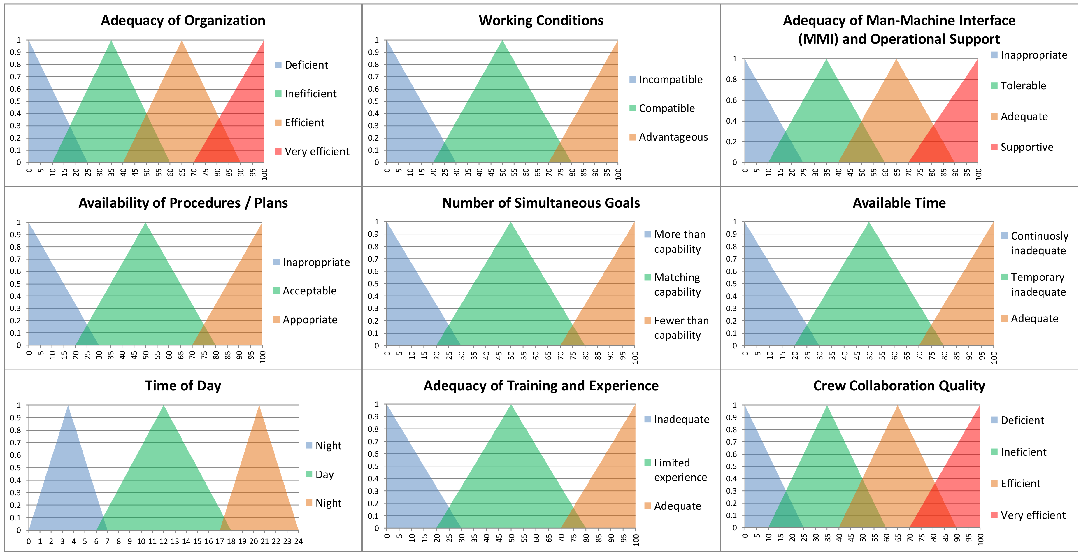
16], the common performance conditions (CPCs) are used as input values to determine the control mode an operator can have in each working situation and consequently, to assess the probability of a possible error. The CPCs, listed in Table 1, consider the working condition, the organizational condition, and the worker’s condition, e.g., in terms of adequacy of training and experience.
Each CPC is divided in three or four subsets. The subsets are described by triangular membership function, as in Figure 1. Each subset can have a different effect on the probability of error: improve, reduce, or not significant.
The FUZZY CREAM output is divided in different levels, representing the levels of control, or control modes, that an operator has in each working context: strategic, tactical, opportunistic, and scrambled control. Output variables are also described through triangular membership function, as shown in Figure 2. Human error probability ranges can be applied to the control mode obtained as output of the FUZZY CREAM, as described in the literature [16] and summarized in Table 2.
Input and output variables are correlated through 46,656 rules, type “if then”. An example is shown in Table 3. The rules are elaborated according to the fuzzy inference procedure, as described in Reference [16].
The centroid method is used for the defuzzification of the results, converting the fuzzy set resulting from the aggregation into a numerical value to be used to classify a control mode and then obtaining a probability of human error. In particular, the centroid method determines the crisp value of output taking into consideration, in a weighted manner, all influences obtained from the rules activated by the particular state of the inputs at a certain moment.

2.2. Explosive Atmosphere (ATEX) Human and Organizational Factors (HOF) Risk Assessment

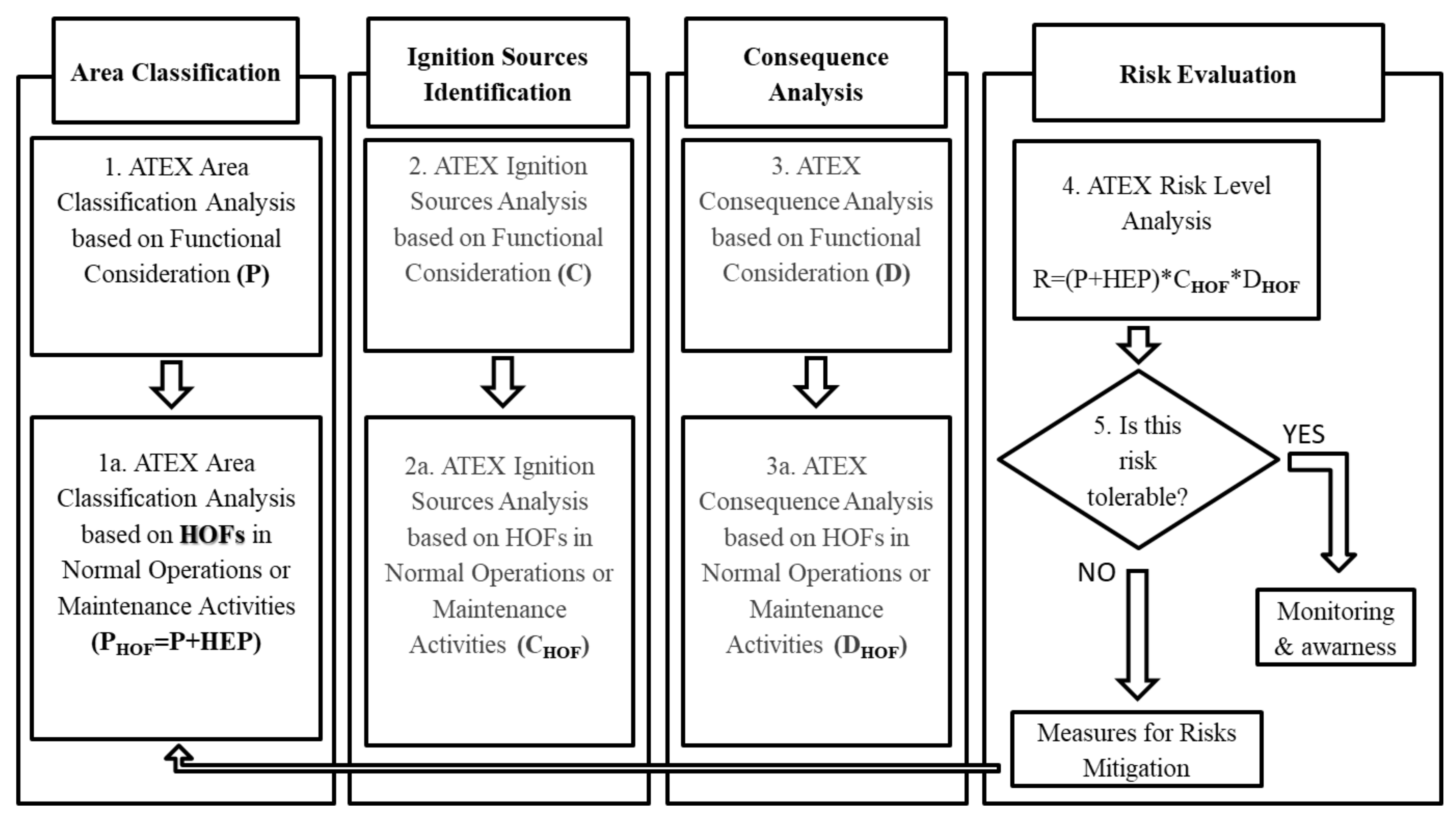
Figure 3 shows the proposed framework for the ATEX risk assessment. As discussed in the introduction section, the semi-quantitative risk assessment relies on four steps: area classification, ignition sources identification, consequence analysis, and risk evaluation. In case the risk should result, tolerable measures for monitoring and awareness are foreseen, while depending on the not tolerable risk level, some intervention indications, in terms of risk mitigation, are summarized in Table 4.
The risk level can thus be assessed according to Equation (1):
RHOF = PHOF × CHOF × DHOF
where, RHOF represents the risk level with the integration of HOF. PHOF represents the probability level of having an explosive atmosphere with the integration of HOF. CHOF represents the probability level of having an ignition source with the integration of HOF. DHOF represents the consequence of having an explosive atmosphere with the integration of HOF.
On the basis of the level of risk estimated for each source, relevant decision making on the safety control can be conducted using as a reference the indications summarized in Table 4, as adapted from Cavaliere and Scardamaglia [10,11].
The evaluation of the parameters composing the risk are described in the following sections.

2.3. Zone Classification

Four categories are available to classify the area at risk, depending on the probability of occurrences of an explosive atmosphere. According to the relevant standards (IEC60079-10-1: 2015 [19] for gas and vapors and IEC60079-10-2: 2015 [20] for dusts), the areas can be classified as:
  • Zone 0 for the gases or Zone 20 for the dust: area where the explosive atmosphere is expected continuously or for long periods.
  • Zone 1 (gases) or 21 (dust): area where occasionally or periodically the presence of explosive atmosphere is possible.
  • Zone 2 (gases) or 22 (dust): area where the presence of explosive atmosphere during the normal activity is not expected or, in case of presence, it is dissolved in a short time.
  • Non-hazardous area: an area where the presence of explosive atmosphere is not expected.
The zone classification is made based on the grade of the release and the effectiveness and availability of the ventilation.
The grade of the release represents the expected frequency at which the flammable gases or combustible dust can be released in the atmosphere. The grade of release is “continue” in case of continuous or long-lasting releases, it is of “primary grade” in case of periodical or occasional releases during normal operations, and it is of “secondary grade” if the release is not expected during normal activity or it is uncommon and for short times. With reference to the dust, it is important to notice that dust layers can also be a source of release.
Once the grade of the release has been assessed, the ventilation, in terms of effectiveness and availability, is considered [21]. The ventilation effectiveness represents the ventilation ability to dilute or remove the potentially explosive cloud in the environment. The ventilation effectiveness can be rated as: high, if the ventilation instantaneously reduces the concentration of the flammable gases or dust below the lower explosive limit, medium, if the ventilation can control the concentration of the potentially explosive atmosphere, and low, if the ventilation cannot control the concentration of the potentially explosive atmosphere.
The ventilation availability is classified as: good, if it is present in continuous, fair, if it is present during the normal activity—infrequent and short-term absence of ventilation is admitted, and poor, not classified otherwise, but with discontinuities not expected for long periods.
The zone classification can thus be carried on according to Table 5, retrieved from CEI (Comitato Elettrotecnico Italiano – Italian Electrotechnical Comity) 31–56 [22], where, depending on the grade of the release, the degree of ventilation, and its availability, the zone classification is obtained.
The above procedure must be applied to all the possible sources of release in the work environment.

2.4. The Effect of Human Factor on Zone Classification

As discussed in References [12,13,23], the zone classification procedure, according to the relevant standards, manual operations, e.g., for maintenance, housekeeping, etc., are assumed to be carried on in a safe and correct way. In the real working conditions, the possible operator errors or misbehaviors cannot be completely neglected and they can increase the probability of the occurrence of explosive atmospheres’ formation (e.g., connecting areas with different classifications or directly generating potential explosive atmospheres, as rising combustible dust layers with inaccurate housekeeping). The event tree referenced, e.g., in Reference [2], is a bottom-up logical and graphical representation of the event sequences, where, from an initiator event, depending on the proper or improper occurrence of influencing events, all the possible consequences are derived. The event tree can also be used in a quantitative way [9], to evaluate the probability of the occurrence of the possible consequences, starting from the probability of the single events disclosed in the event tree. In 
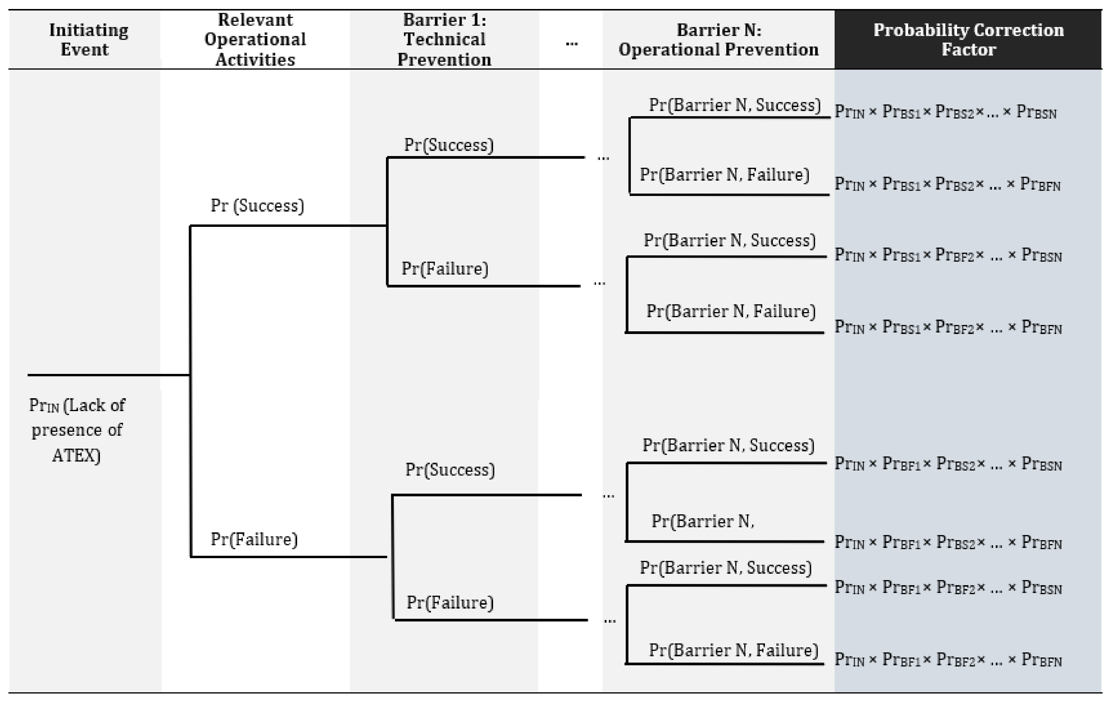
Figure 4, the framework of the method is proposed.
The probability of the lack of presence or generation of explosive atmosphere in the area under analysis due to causes other than human and organizational factors constitutes the initiating event. The relevant operational activities that could result in an increase of the likelihood of ATEX formation are then considered. Thus, in the construction of the event tree, the following are considered: the effectiveness of the recovery activity, organizational (procedural activity), or technological (technical system). The effectiveness is evaluated in terms of probability of failure, for the technological system, or the error, for the procedural activity. The probability of operator error is evaluated through the FUZZY CREAM, according to the procedure described in the previous section. The correction factor will be calculated as the sum of the probabilities of all the sequences disclosed in the event tree that could bring about the generation of a flammable atmosphere, otherwise not present.
The calculation of the correction factor as for the last column in Figure 4 assumes that all the terms are independent. In case this assumption should not be confirmed, the calculations should take into account the dependencies, otherwise final probability should have been underestimated.
The probability correction factor calculated from the event tree is added to the initial ATEX probability and used for the zone classification.

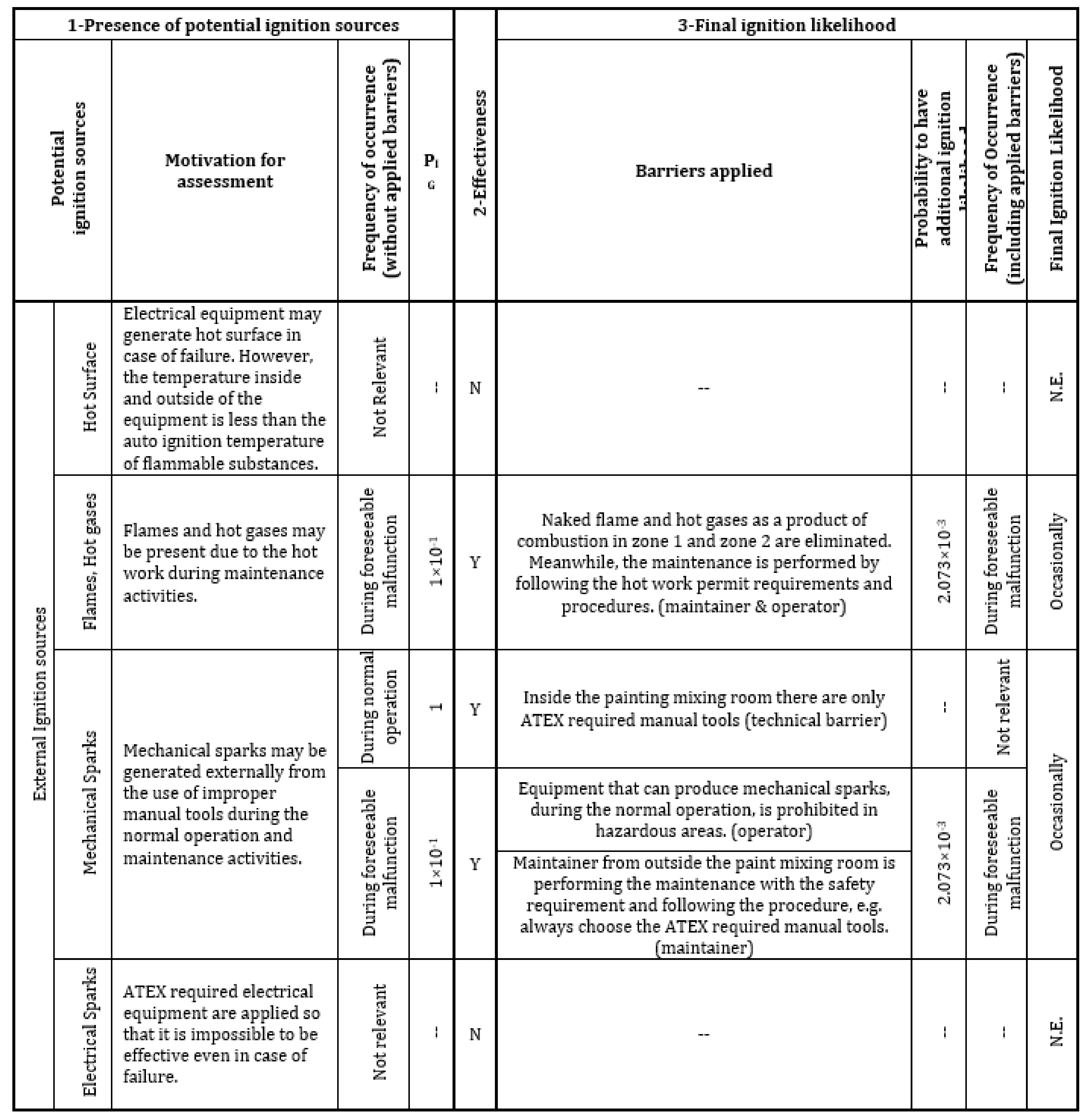
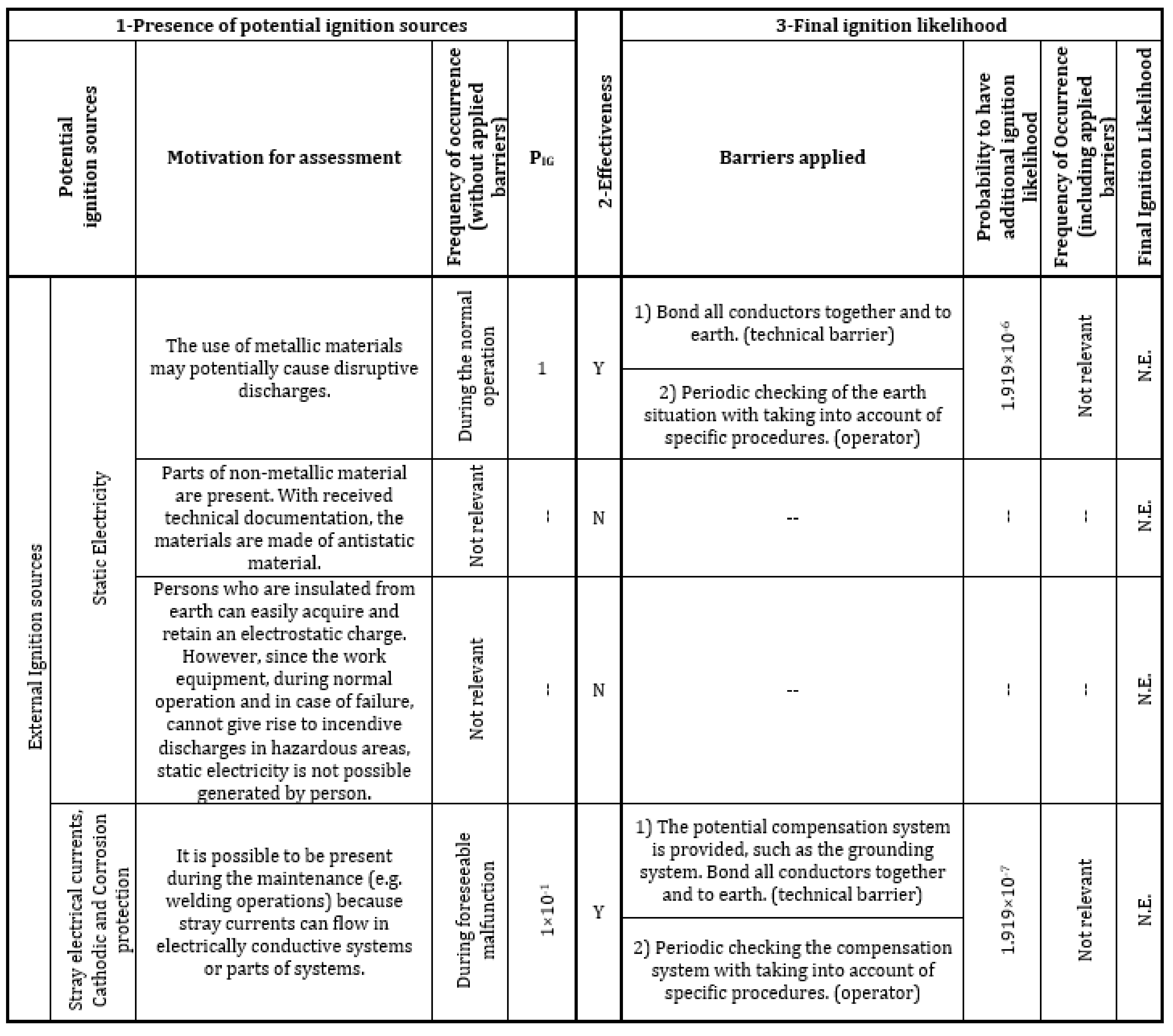
2.5. Ignition Source Assessment

Ignition source assessment is the second step to go through when the zone classification is determined as a dangerous one. Relevant ignition sources are listed in the technical standard EN 1127-1 [24] and shown in Table 6.
To assess the presence and effectiveness of ignition sources and their probability, the technical standard ISO EN 80079-36:2016 [25] has been used as a reference. The standard aims at providing the basic method and requirements for design, construction, testing, and marking of non-electrical equipment intended for use in potentially explosive atmospheres. It provides a scheme for the ignition source identification. Once the potential ignition sources are identified, the frequency of occurrence can be assessed (Table 7). An example of application of the Table 7 can be found in Section 3.
The assessment of the effectiveness of the ignition sources can be conducted quantitatively, but more often, it has to be conducted in a qualitative way. For example, in order to have an effective hot surface, the maximum surface temperature under the most adverse operation condition should be taken into account. For some of the ignition sources, specific standards exist to support their assessment (e.g., CLC/TR 679-32-1: 2016 for static electricity). The probability of the presence of ignitions sources is then estimated coherently with the ranges adopted for zone classification (Table 8).
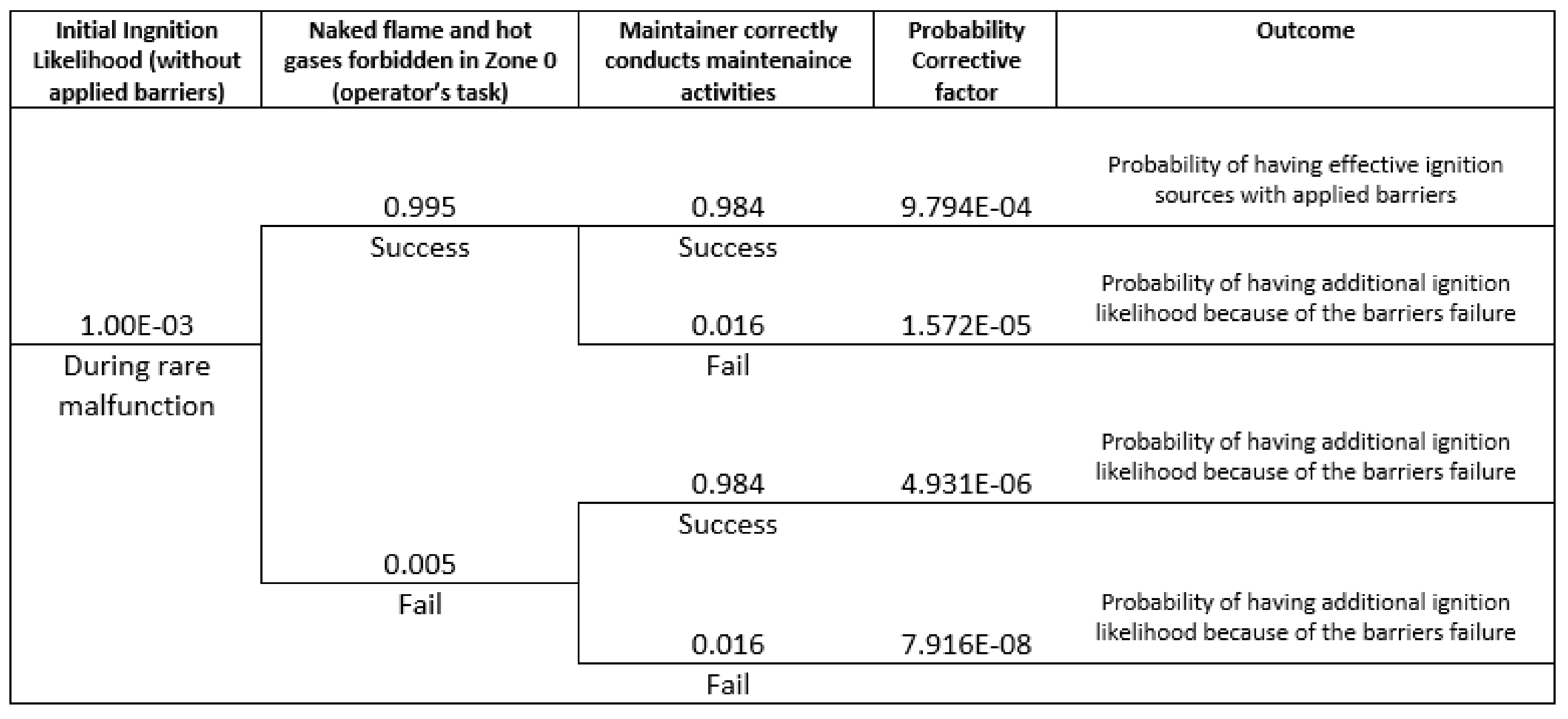
In case an identified potential ignition source results to be effective, applied barriers should be considered. Also, in this case, an event tree is built. The initial event is represented by the initial probability of the ignition source (PrIG).
Alternative paths are then built by applying barriers and/or relevant operational activities. The probability of failures can be the result of the technical barrier failure (Pr,tbf) and/or of human errors or recovery (HEP). The probability calculation along the sequences of events allows to evaluate the likelihood of having an initial/additional effective ignition source.
In the end, the ATEX-HOF ignition source assessment for each emission source is carried on (Table 9). The maximum value of the ignition likelihood among all identified potential ignition sources will be chosen for the risk assessment, in order to have a conservative evaluation, and will allow for determining the CHOF index to be used in risk estimation, according to reference Table 8. A worked example of that described above is shown in Section 3.

2.6. Damage Analysis

The Damage analysis relies on the area classification result (represented as the ID index which can be determined with Table 10 and other factors summarized in Table 10: personnel presence (PL), dust explosion index (KST), gas explosion index (KG), cloud volume (VZ), layer thickness (SS), confined dust cloud (CN), as detailed in References [4,5] and summarized in Table 11. The semi-quantitative parameter, DHOF, can be then calculated according to Equations (2) or (3).
DHOF = IDHOF + PL + KST + VZ + SS + CN (for dust)
DHOF = IDHOF + PL + KG + VZ + CN (for gas)

2.7. Case Study

The case study refers to the central paint mixing station in an automotive manufacturing plant, located in Serbia. Primer, coat, paints, and solvents contain flammable substances that can potentially generate explosive gas atmospheres during normal operations. Ten groups of emission sources were identified which were separated in different rooms of the paint mixing station: storage room, solvent mixing room, and paint mixing room. Inside the paint mixing room, the basic paint mixing unit was selected as a case study to apply the ATEX-HOF methodology.
The basic paint mixing unit has a double tank for the preparation and pumping of high consumption paint. A 1 m3 container with the product provided by the supplier of the product is positioned on the relative support close to the group. The flexible suction tube is connected, and the product is transferred to the preparation tank through transfer pumps. In the preparation tank, the product is diluted by adding dilution solvent, checking the quantity using a manual liter counter. The product is mixed using the electric shaker fitted on the cover. The product created in this way is transferred to the working tank through a membrane pump, therefore making the preparation tank ready for a new preparation cycle. The electric pump powers the distribution circuit, keeping the product in re-circulation. The pressure in the re-circulation circuit is controlled and maintained by means of a return regulator. A signal generated by the supervision system informs the operator that the minimum level has been reached.
The management group and the loading of products is completely manual. The operator is responsible for controlling these operations acting on the panel of selectors and the control flow meter. The station is staffed by three daily shifts. Each shift (8 h per day) mainly has one shift leader, two operators, and one daily maintainer. The paint mixing operation is a 365 day operation. The paint mixing is a one-by-one operation, two simultaneous mixing operations are prohibited.

3. Results

3.1. Area Classification

Each item of the process equipment which contains flammable materials was considered as a potential emission source, as seen in Table 12.
The type of the area classification inside the equipment can be referred to the grade of release and the ventilation conditions. It is generally conducted in a qualitative way. According to Table 4, the internal zones for each identified emission source were determined, resulting in all zones being 0.
Then, the external zone was evaluated and updated to take into account the effect of potential operational errors. Considering that the relevant operations (and/or operational barriers) are conducted by two people, one is the operator performing daily tasks during normal operation conditions (Scenario 1), and another is the maintainer, conducting the maintenance activities (Scenario 2). The Human Error Probabilities (HEP) were estimated by applying FUZZY CREAM (Table 13) according to the procedure described in Section 2.1.
The HEP data have been introduced in the event tree generated to describe the real operational activity in the plant, and the zone classification for both internal, PrIN, and external, PrEXT, sides of the basic paint mixing unit were determined (Table 14).
As a result, the area classification from both internal and external sides of the basic paint mixing unit were determined. In the end, the envelop of external zones were drawn on the layout to highlight the critical area.

3.2. Ignition Source Assessment

Ignition source assessment is the second step to go through if the zone classification is determined as a dangerous zone. The 13 possible ignition sources have been evaluated according to the methodology in Section 2. For the effective ignition sources, barriers have been considered. In this basic paint mixing unit, there is one technical barrier applied: the ground system, with a failure probability of Ptbf = 3.83 × 10⁻⁴, as assessed by the plant technicians. Two operational barriers are present. According to the general working context and their working performances, the HEP were estimated by applying FUZZY CREAM, as seen in Table 13.
From the analysis, it emerged that the most critical ignition sources are “Flame”, “Hot gases” and “Mechanical sparks”, with an estimated probability of occurrence of 2.073 × 10⁻³, corresponding to a likelihood label of “occasionally”. This value has been considered in the risk assessment. Figure A1 and Figure A2 in the Appendix A summarize the whole ATEX-HOF ignition source assessment respectively, inside and outside the tank object of the case study.
Figure 5 shows an example of the applied event trees for the analysis of human errors and barriers, with reference to flames and hot gases due to hot works.

3.3. Risk Assessment

Given the parameters evaluated in previous paragraphs, the ATEX-HOF risk evaluation results for the basic paint mixing unit are shown in Table 15 for the case of the success of the applied technical barrier and human intervention, and in Table 16 for the case of failures in the applied technical barrier and human intervention.
As mentioned above, the risk level of the basic paint mixing unit resulted negligible for all the identified emission sources (internal and external sides) in case the following barriers are applied and/or relevant operational activities are performed correctly:
  • Naked flame and hot gases as a product of combustion are forbidden in zone 0, and in zone 1 and zone 2 are eliminated.
  • The maintenance is performed under the safety requirements (e.g., hot work permit).
  • The maintenance is performed following the required procedures.
  • Equipment that can produce mechanical sparks is prohibited in hazardous areas.
  • Periodic checking of the grounding system is included in operational procedures.
  • Inside the paint mixing room, only ATEX certified tools are available and used.
  • Operators inside the room are always wearing the antistatic clothes and shoes.
  • The ATEX risk assessment has to be evaluated in case of any change, related to operators, maintainers, operations, or equipment.
However, when the probability of failure of applied barriers and/or relevant operational activities is considered, the risk level of the basic paint mixing increases from the “negligible” to the “low” level. According to Table 11, risk mitigation measures should be implemented in a long time interval.

4. Discussion

4.1. Effectiveness of ATEX-HOF

ATEX-HOF methodology deals with the HOF influence on the identified ATEX hazards. The event tree-based probabilistic assessment method has been introduced in order to quantify the HOF influence. The effectiveness of the method strongly depends on the initial level of safety management within the plant in which it is applied:
(1)
If the safety management is already consolidated in the plant, safety procedures exist and are followed, and the operators are trained and aware of the hazards, results from the ATEX-HOF methodology will be in line with those of the traditional methodology.
(2)
If the safety management in the plant is not consolidated, then the application of the ATEX-HOF methodology will give different results with respect to the traditional methodology and will help in improving the level of safety for the operators and the equipment.

4.2. Cost-Benefit Analysis

The ATEX-HOF methodology resulted to be effective as discussed above, but it requires some additional efforts: the additional time consumed for the risk assessment, people involved, process interruption, and more data requirement are considered. For each analysis, an additional 2–4 min is required. The additional source supports are the FUZZY CREAM tool and the event tree instrument, otherwise not used in ATEX risk assessment. Additional works include: (a) identification of applied technical barriers and human interventions, (b) estimation of failure probability of applied technical barriers and relevant human interventions, and (c) event tree analysis.

4.3. Feedback from the Stakeholders

Feedback was collected from the industry where the ATEX-HOF methodology was applied. A questionnaire survey was conducted. The responses are summarized here: (a) The ATEX-HOF methodology covered the process phases: design phase, normal operation, maintenance, and non-routine situation. (b) It is necessary to consider HOF within the ATEX risk assessment, and the ATEX-HOF methodology is helpful for the HOF influence analysis. (c) The results coming from the ATEX-HOF methodology clearly support decision making. (d) The application does not disturb the operations. However, (a) half of the responses concern a high-level of education needed, in order to apply the methodology and (b) half of the responses concern that conducting the quantitative analysis is a little time consuming.

5. Conclusions

The ATEX-HOF methodology provides a quantitative risk analysis approach to the potentially explosive atmosphere hazards, that includes the human and organizational factors (HOFs). Within each phase of the analysis, clear assessment goals were identified. An event tree-based probabilistic assessment has been introduced. Hence, the ATEX-HOF risk assessment becomes more complete than the traditional approach.
The application to case studies of industrial interest showed how taking HOFs into account is particularly important in companies where the usual hypothesis of the correctness of operator intervention (in maintenance, normal operations, and emergency) could bring to non-conservative results. In fact, the case study developed has shown how taking the human factors into account could bring higher risk to the assessment than the one calculated with the traditional methodology and the inherent assumption that operations are correctly carried on. The potential underestimation of the risk with the traditional risk assessment would negatively affect the decision-making process in terms of safety of the operators and the assets.
An underestimation could also occur in the case of dependencies among operational errors or between operational errors and technical failures. In case a dependency should be evidenced, and this is at the moment left to the experience of the risk analyst, this should be addressed in the calculation in order to avoid possible inaccuracies.
The applied operational (HOF) barriers included in the analysis can be used as a reference for the development of a more detailed set of operational procedures, that will allow the level of risk to be maintained in time.

Author Contributions

Conceptualization, M.D. and S.M.; methodology, S.M. and J.G.; software, G.B.; validation, J.G. and G.B.; formal analysis, G.B.; writing—original draft preparation, J.G. and G.B.; writing—review and editing, S.M. and M.D.; supervision, M.D. All authors have read and agreed to the published version of the manuscript.

Funding

This paper originates from the research carried on under the FP7 People Marie Curie ITN Project InnHF—Innovation through human factors in risk analysis and management Grant agreement ID: 289837.

Acknowledgments

The authors gratefully acknowledge the cooperation of FCA Serbia for the fruitful discussions with plant technicians and HSE managers who helped with validating the methodology.

Conflicts of Interest

The authors declare no conflict of interest.

Appendix A

Figure A1. Internal ignition sources estimation within the ATEX-HOF methodology.
Safety 06 00005 g0a1
Figure A2. External ignition sources estimation within the ATEX-HOF methodology (part I).
Safety 06 00005 g0a2
Figure A3. External ignition sources estimation within the ATEX-HOF methodology (part 2).
Safety 06 00005 g0a3

References

  1. European Parliament and of the Council. Directive 2014/34/EU the Harmonisation of the Laws of the Member States Relating to Equipment and Protective Systems Intended for Use in Potentially Explosive Atmospheres (Recast); European Parliament and of the Council: Bruxelles, Belgium, 2014. [Google Scholar]
  2. Mannan, S. Lee’s Loss Prevention in the Process Industries; Elsevier: Oxford, UK, 2005. [Google Scholar]
  3. Piccinini, N.; Demichela, M. Risk based decision-making in plant design. Can. J. Chem. Eng. 2008, 86, 316–322. [Google Scholar] [CrossRef]
  4. Murè, S.; Comberti, L.; Demichela, M. How harsh work environments affect the occupational accident phenomenology? Risk assessment and decision making optimization. Saf. Sci. 2017, 95, 159–170. [Google Scholar] [CrossRef]
  5. Baldissone, G.; Fissore, D.; Demichela, M. Catalytic after-treatment of lean VOC-air streams: Process intensification vs. plant reliability. Process Saf. Environ. Prot. 2016, 100, 208–219. [Google Scholar] [CrossRef]
  6. Demichela, M.; Baldissone, G.; Camuncoli, G. Risk-Based Decision Making for the Management of Change in Process Plants: Benefits of Integrating Probabilistic and Phenomenological Analysis. Ind. Eng. Chem. Res. 2017, 56, 14873–14887. [Google Scholar] [CrossRef]
  7. Baldissone, G.; Demichela, M.; Camuncoli, G.; Comberti, L. Formaldehyde production plant modification: Risk based decision making. Chem. Eng. Trans. 2017, 57, 703–708. [Google Scholar]
  8. Markowski, A.S.; Mannan, M.S.; Bigoszewska, A. Fuzzy logic for process safety analysis. J. Loss Prev. Process Ind. 2009, 22, 695–702. [Google Scholar] [CrossRef]
  9. Center for Chemical Process Safety. Guidelines for Chemical Process Quantitative Risk Analysis; AIChE: New York, NY, USA, 2000. [Google Scholar]
  10. Cavaliere, A.; Scardamaglia, P. Guida All’applicazione Delle Direttive ATEX; EPC S.R.L.: Roma, Italy, 2005. [Google Scholar]
  11. Cavaliere, A. Manuale per l’applicazione Della Direttiva ATEX; EPC S.R.L.: Roma, Italy, 2011; pp. 331–333. [Google Scholar]
  12. Geng, J.; Mure, S.; Camuncoli, G.; Demichela, M. Integration of HOFs into ATEX risk assessment methodology. Chem. Eng. Trans. 2014, 36, 583–588. [Google Scholar]
  13. Geng, J.; Mure, S.; Baldissone, G.; Camuncoli, G.; Demichela, M. Human Error Probability Estimation in ATEX-HMI Area Classification: From THERP to FUZZY CREAM. Chem. Eng. Trans. 2015, 43, 1243–1248. [Google Scholar]
  14. Swain, A.D.; Guttman, H.E. Handbook of Human Reliability Analysis with Emphasis on Nuclear Power Plant Applications (NUREG CR-1278); Sandia National Labs: Albuquerque, NM, USA, 1983. [Google Scholar]
  15. Hollnagel, E. Cognitive Reliability and Error Analysis Method; Elsevier: Oxford, UK, 1998. [Google Scholar]
  16. Konstandinidou, M.; Nivolianitou, Z.; Kiranoudis, C.; Markatos, N. A fuzzy modeling application of CREAM methodology for human reliability analysis. Reliab. Eng. Syst. Saf. 2006, 91, 706–716. [Google Scholar] [CrossRef]
  17. Marseguerra, M.; Zio, E.; Librizzi, M. Human Reliability Analysis by Fuzzy “CREAM”. Risk Anal. 2007, 27, 137–154. [Google Scholar] [CrossRef] [PubMed]
  18. Monferini, A.; Konstandinidou, M.; Nivolianitou, Z.; Weber, S.; Kontogiannis, T.; Kafka, P.; Kay, A.M.; Leva, M.C.; Demichela, M. A compound methodology to assess the impact of human and organizational factors impact on the risk level of hazardous industrial plants. Reliab. Eng. Syst. Saf. 2013, 119, 280–289. [Google Scholar] [CrossRef]
  19. International Electrotechnical Commission. IEC 60079-10-1, Explosive Atmospheres-Part 10-1: Classification of Areas-Explosive Gas Atmospheres; International Electrotechnical Commission: Geneva, Switzerland, 2015. [Google Scholar]
  20. International Electrotechnical Commission. IEC 60079-10-2, Explosive Atmospheres-Part 10-2: Classification of Areas-Explosive Dust Atmospheres; International Electrotechnical Commission: Geneva, Switzerland, 2015. [Google Scholar]
  21. Borchiellini, R.; Cardu, M.; Labagnara, D.; Martinetti, A.; Patrucco, M.; Colella, F.; Verda, V.; Sandrin, D. Prevention through Design approach for the ventilation system of an Italian quarry. Chem. Eng. Trans. 2013, 32, 181–186. [Google Scholar]
  22. Comitato Elettrotecnico Italiano. CEI 31-56, Equipment for Use in the Presence of Combustible Dust—Guide for Classification of Hazardous Area; Comitato Elettrotecnico Italiano: Milano, Italy, 2007. [Google Scholar]
  23. Baldissone, G.; Camuncoli, G.; Demichela, M.; Murè, S. Human and Organizational Factors (HOF) in ATEX Risk Assessment [Fattori umani e organizzativi nella valutazione del rischio ATEX]. Geoingegneria Ambientale e Mineraria 2017, 150, 29–36. [Google Scholar]
  24. European Committee for Standardization. EN UNI 1127-1, Explosive Atmospheres-Explosion Prevention and Protection-Part 1: Basic Concepts and Methodology; UNI: Milano, Italy, 2011. [Google Scholar]
  25. European Committee for Standardization. EN ISO 80079-36:2016 Explosive Atmospheres-Part 36: Non-Electrical Equipment for Explosive Atmospheres-Basic Method and Requirements (ISO 80079-36:2016); UNI: Milano, Italy, 2016. [Google Scholar]
Figure 1. Common performance conditions (CPCs) membership functions.
Safety 06 00005 g001
Figure 2. Output membership functions—control modes. Of probability interval
Safety 06 00005 g002
Figure 3. Proposed framework for explosive atmosphere (ATEX) risk assessment.
Safety 06 00005 g003
Figure 4. Event tree structure for the external zone determination.
Safety 06 00005 g004
Figure 5. Fault tree assessment of the ignition source probability corrective factor in case of hot works.
Safety 06 00005 g005
Table 1. Common performance conditions in cognitive reliability and error analysis method (CREAM) as fuzzy input sets.
InputsRangeFuzzy SetsLevel/DescriptorsMembership Level Intervals
Adequacy of Organization[0, 100]4Very Efficient70–100
Efficient40–90
Inefficient10–60
Deficient0–25
Working Conditions[0, 100]3Advantageous70–100
Compatible20–80
Incompatible0–30
Adequacy of MMI and Operational Support[0, 100]4Supportive70–100
Adequate40–90
Tolerable10–60
Inappropriate0–25
Availability of Procedures/Plans[0, 100]3Appropriate70–100
Acceptable20–80
Inappropriate0–30
Number of Simultaneous Goals[0, 100]3Fewer than capacity70–100
Matching current capacity20–80
More than capacity0–30
Available Time[0, 100]3Adequate70–100
Temporarily inadequate20–80
Continuously inadequate0–30
Time of Day (Circadian Rhythm)[0, 24]3Night-time16–24
Day-time8–17
Night-time0–9
Adequacy of Training and Experience[0, 100]3Adequate, High Experience70–100
Adequate, Limited Experience20–80
Inadequate0–30
Crew Collaboration Quality[0, 100]4Very efficient70–100
Efficient40–90
Inefficient10–60
Deficient0–25
Table 2. Control Modes and Human Failure Probability.
Level/DescriptorsHuman Error Probability Ranges
Strategic0.5 × 10−5 ˂ p ˂ 1 × 10⁻²
Tactical1 × 10−3 ˂ p ˂ 1 × 10⁻¹
Opportunistic1 × 10−2 ˂ p ˂ 0.5
Scrambled1 × 10−1 ˂ p ˂ 1
Table 3. Example of fuzzy inference rule.
IF Adequacy of Organization is “very efficient”,
AND Working Conditions is “advantageous”,
AND Adequacy of Man-Machine Interface (MMI) and Operational Support is “supportive”,
AND Availability of Procedures/Plans is “appropriate”,
AND Number of Simultaneous Goals is “fewer than capacity”,
AND Available Time is “adequate”,
AND Time of Day (Circadian Rhythm) is” unadjusted Night-time”,
AND Adequacy of Training and Experience is “adequate with high experience”,
AND Crew Collaboration Quality is “very efficient”
THEN output is Strategic control mode.”
Table 4. Risk-based decision making indications.
Value (R)Risk LevelDescriptionRisk Control
RHOF ≥ 18HighHigh likelihood of presence of explosive atmosphere. Ignition sources are present and effective. Consequences of an explosion are extremely serious. Likelihood of explosion propagation is very high.Risk mitigation measures must be implemented.
9 ≤ RHOF < 18MediumLikely presence of explosion atmosphere and ignition sources can be present and effective. In case of an explosion, consequences are moderate with marginal damage to personnel and process units. Explosion propagation is likely to be moderate.Risk mitigation measures should be implemented in a short time interval.
1 ≤ RHOF < 9LowThe likelihood of the presence of an explosive atmosphere is extremely limited, as well as the presence of effective ignition sources. The exposure level is low, so with limited damage to persons and property. The probability of propagation of the explosion is to be considered as extremely limited.Risk mitigation measures should be implemented in a long time interval.
RHOF ≤ 1NegligibleLikelihood of explosion atmosphere presence is very low, or ignition sources are not present, or they are not effective. There are not consequences to personnel or equipment. Explosion propagation is very unlikely to occur.Operations should be kept monitored in order to control the risk in this level.
Table 5. Influence of the ventilation on the type of zone.
Grade of ReleaseVentilation
Degree
HighMediumLow
Availability
GoodFairPoorGoodFairPoorAny
Continuous(Zone 0 NE) Non-hazardous a(Zone 0 NE) Zone 2 a(Zone 0 NE) Zone 1 aZone 0Zone 0 + Zone 2Zone 0 + Zone 1Zone 0
Primary(Zone 1 NE) Non-hazardous a(Zone 1 NE) Zone 2 a(Zone 1 NE) Zone 2 aZone 1Zone 1 + Zone 2Zone 1 + Zone 2Zone 1 or Zone 0 c
Secondary b(Zone 2 NE) Non-hazardous a(Zone 2 NE) Non-hazardous aZone 2Zone 2Zone 2Zone 2Zone 1 and Zone 0 c
a Zone 0 NE, 1 NE, or 2 NE indicate a theoretical zone which would be of negligible extent (NE) under normal conditions. b Zone 2 area created by a secondary grade of release may exceed that attributable to a primary or continuous grade of release. In this case, the greater distance should be taken. c Zone 0 if the ventilation is so weak and the release is such that in practice an explosive gas atmosphere exists virtually continuously (i.e., approaching a ‘no ventilation’ condition). ‘+’ means ‘surrounded by’.
Table 6. Possible ignition sources according to EN 1127-1.
Hot SurfacesStray Electric Currents, Cathodic Corrosion ProtectionUltrasounds
Flames, hot gasesLightningAdiabatic compression and shockwaves
Mechanical sparksElectromagnetic wavesExothermic reactions
Electrical apparatusIonizing radiations
Static electricityHigh-frequency radiation
Table 7. Scheme for the identification and assessment of ignition sources.
#123
#Potential Ignition SourcesAssessment of the Frequency of Occurrence without Applied BarriersEffectiveness (Y/N)
ababcde
Potential Ignition SourcesDescription/ Basic CauseDuring normal operationDuring foreseeable malfunctionDuring rare malfunctionNot relevantReasons for assessment
Table 8. Linking probability ranges with the ignition likelihood.
Ignition LikelihoodFrequency of Occurrence Assessment for Ignition Sources [23]Probability RangesC or CHOF
FrequentlyDuring normal operationp > 10−13
OccasionallyDuring foreseeable malfunction10−1p > 10−32
RarelyDuring rare malfunction10−3p > 10−51
Not ExpectedNot relevant10−5 > p0
Table 9. Final ignition likelihood estimation.
4567
Measures applied to prevent the ignition source becoming effectiveInitial Ignition ProbabilityFrequency of occurrence including applied measuresIgnition
Likelihood
abcabcd
Description of the measure appliedBasis (standards, technical rules, experimental results)Technical documentationDuring normal operationDuring foreseeable malfunctionDuring rare malfunctionNot relevant
Table 10. The semi-quantitative ranking system for the ATEX-HOF risk evaluation.
Area ClassificationSemi Quantitative Ranking
DegreeID or IDHOF
Zone 0/20Frequently0.6
Zone 1/21Occasionally0.4
Zone 2/22Rarely0.2
Zone NEN.E.0
Table 11. Indexes for the DHOF value estimation.
FactorsUnitsIndexes
00.20.40.6
Zone NEZone 2 or Zone 22Zone 1 or Zone 21Zone 0 or Zone 20
Personnel presence (PL)--Absent of WorkOccasional WorkIntermittent WorkContinuous Work
Dust explosion index (Kst)(bar × m/s)<1010 to 5051 to 100>100
Gas explosion index (KG)(bar × m/s)<1010 to 5051 to 100>100
Cloud volume (VZ)(dm3)0≤11 ≤ 10>10
Layer thickness (SS)(mm)Absent≤55 ≤ 50>50
Confined Dust Cloud (CN)--Not ExpectedNot ConfinedPartly ConfinedCompleted Confined
Table 12. Emission sources identification for the basic paint mixing unit.
Emission SourcesQuantityInternal Sources of ReleaseExternal Sources of Release
Paint Loading Container1000 L Paint Loading Container1Liquid surface within the paint loading container
  • Openings in the loading container.
  • Leakage of liquid close to the loading container.
Fixed Process Mixing Vessels2000 L Fixed Process Mixing Vessel2Liquid surface within the mixing vessel
  • Vent openings and other openings in the mixing vessel.
  • Spillage or leakage of liquid close to the mixing vessel.
Supply SystemFilter S.S. 20″1Liquid surface within the supply system
3.
Structural emission from connectors and gaskets.
4.
Leakage from seals, flanges, pipe fittings, and other connectors in case of failure.
Filter S.S. PN-16 10″2
Electric Pump2
Pneumatic Diaphragm Pump1
Valves62
Hoses3
Table 13. HEP estimation through FUZZY CREAM.
ScenarioCPC 1CPC 2CPC 3CPC 4CPC 5CPC 6CPC 7CPC 8CPC 9HEP
Scenario 1
Daily operations
8070708070701475705.01 × 10−3
Scenario 2
Maintenance
7065206525501660101.58 × 10−2
Table 14. Results of zone classification according to the ATEX-HOF methodology.
Internal Source of ReleaseGrade of ReleaseInternal ZonePrINExternal Source of ReleaseGrade of ReleaseRelevant Operational Activities and/or Applied BarriersInitial External Zone PrHOF,EXTExternal Zone
The paint loading container (1000 L)Liquid surface within the loading container ContinuousZone 01 (365 days operations)Openings in the paint loading containerPrimaryOperator is correctly checking and monitoring parameters by following designed procedures.Zone 15.01 × 10⁻³Zone 1
Leakage of liquid close to the paint loading container.SecondaryOperator is performing periodical inspection.Zone 25.01 × 10⁻⁶Zone 2
The fixed process mixing vessel (2000 L)Liquid surface within the mixing vesselContinuousZone 01 (365 days operations)Vent openings and other openings in the mixing vessel.PrimaryOperator is correctly checking and monitoring parameters by following designed procedures.Zone 15.01 × 10⁻³Zone 1
Spillage or leakage of liquid close to the mixing vessel.SecondaryOperator is performing periodical inspection.Zone 22.073 × 10⁻²Zone 1
Any performed maintenance work follows procedures, e.g., replacement of grate guard and cleaning activities.
Supply systemLiquid surface within the supply systemContinuousZone 01 (365 days operations)Structural emission from connectors and gaskets.PrimaryReplacement and adequate maintenance. (maintainer)Zone 11.58 × 10⁻² Zone 1
Leakage from seals, flanges, pipe fittings, and other connectors in case of failure.SecondaryOperator is performing periodical inspection.Zone 22.073 × 10⁻²Zone 1
Replacement and adequate maintenance.
Note: General artificial ventilation condition, Grade: Low inside and Medium outside, Availability: Good.
Table 15. Traditional ATEX Risk evaluation result for the basic paint mixing unit.
Emission SourceArea ClassificationPEffectiveness of Ignition SourceCDR = P × C × DRisk Level
Paint Loading ContainerInternal (liquid surface)3Internal: Not relevant03R < 1Negligible
External (opening)2External: Not relevant02R < 1Negligible
External (leakage)101R < 1Negligible
Fixed processmixing vesselInternal (liquid surface)3Internal: Not relevant03R < 1Negligible
External (opening)2External: Not relevant02R < 1Negligible
External (leakage)11R < 1Negligible
Supply systemInternal (liquid surface)3Internal: Not relevant03R < 1Negligible
External (structural emission)2External: Not relevant02R < 1Negligible
External (leakage)11R < 1Negligible
Note: P is the probability level of having an explosive atmosphere; C is the probability level of having an ignition source; and D is the consequence of having an explosive atmosphere.
Table 16. ATEX-HOF risk evaluation result for the basic paint mixing unit.
Emission SourceArea ClassificationPHOFEffectiveness of Ignition SourceCHOFDHOFRHOF = PHOF × CHOF × DHOFRisk Level
Paint Loading ContainerInternal (liquid surface)3Internal: Rarely139Low
External (opening)2External: Occasionally228Low
External (leakage)228Low
Fixed process mixing vesselInternal (liquid surface)3Internal: Rarely139Low
External (opening)2External: Occasionally228Low
External (leakage)228Low
Supply systemInternal (liquid surface)3Internal: Rarely139Low
External (structural emission)2External: Occasionally228Low
External (leakage)228Low

