Abstract
Electronic waste stream grows day by day; printed circuit boards are a kind of solid waste that accounts for 6% of electronic waste. When these are discarded, they can cause soil, water, and air contamination; however, if recycled, these can be considered as a secondary source of metals. Physical comminution of printed circuit boards generates particles with sizes smaller than 250 µm, which are typically not included in the recycling process because they are considered as dust and unvaluable; nevertheless, precious and base metals can be found in these particles. The concentration of metals like silver, among others, from these particles can be achieved by reverse froth flotation in a flotation column followed by magnetic separation of the tails products. A mass balance of the flotation column feed, concentrate, and tails indicates that using a pulp modified with 5 ppm methyl isobutyl carbinol plus 5 g/ton oleic acid (both biodegradable reagents), the concentration of the products improved, resulting in recoveries of 86.13 and 13.87% in the concentrate and tails zones, respectively, with a grade of 74.4% in the tails flow. Magnetic separation of the tails product increases slightly the concentration of silver, reaching a silver grade of 74.5%, a recovery amount similar to those obtained employing complex and environmentally unfriendly processes.
1. Introduction
The number of electronic devices has increased in recent years, at the same time as a vast generation of end-of-life electrical and electronic equipment (EOL-EEEs) has been created. Printed Circuit Boards (PCBs) are essential components of these devices and account for 6% of the EOL-EEEs [1]. PCBs are boards consisting of fiberglass-reinforced epoxy resin which support several components which may content metals, reported as average values, like precious metals: silver (0.16%), gold (0.05%), platinum (0.002%), and palladium (0.005%), as well as base metals: copper (21.60%), nickel (1.17%), tin (2.85%), and lead (2.11%), among others; these metals are employed due their electrical and thermal conductivity properties [2,3,4,5,6].
The recovery of valuable materials from EOL-EEE waste that is generated every day can be a viable source to supply the growing demand for raw materials; concentration of metals like silver from PCBs can represent more than 80% of the total intrinsic value; it is much higher than their respective primary resources [5,7] and allows reducing waste and pollution, producing new processes and products and contributing to the regeneration of nature through the principles of the circular economy (CE) [8]. Electronic equipment is built using PCBs containing metals, polymers, and ceramics. Depending on the way electronic equipment is treated at the end of its shelf life, some of these materials can cause air, soil, subsoil, or water contamination [9,10,11,12,13].
Many techniques for the recovery of valuable materials from EOL-EEEs are currently in use, some of which are more environmentally friendly than others, such as the case of the reverse froth flotation technique in a flotation column when no contaminating chemical reagent is employed, as reported by some authors in [1], which involves the selective separation of the different fractions after a prior size reduction. Some particles are hydrophobic, while others are hydrophilic, resulting in the separation of the nonmetallic fraction (NMF) and the metallic fraction (MF). This operating principle is similar to that of flotation cells, with the difference that the column is a vertical reactor with a large collection and froth zone, which favors the selective separation of fractions [1,10,14]. Further magnetic separation of tails products from reverse froth flotation, where magnetic metals are separated from the nonmagnetic metals, generates a high concentration of these.
PCBs are plates built from a mixture of epoxy resins reinforced with fiberglass, and embedded metals; this kind of PCB, present in most electronic devices, is used to connect a wide variety of electronic components, such as resistors, capacitors, relays, integrated circuits, connectors, piezoelectrics, etc., via a conductive track; some of these components can be removed and reused, while others must be removed prior to the recycling process to avoid subsequent contamination; however, many other components can remain mounted to be processed along with PCBs during the recycling process [1,10,15].
Several PCB recycling techniques start with the dismantling of all of the components mounted on them to obtain a bare board, which is then processed, eliminating all cross-contamination from extra components. To obtain a bare board, the PCB is heated to melt and recover the tin, lead, or silver, which are the metals found in most solders that connect electronic components to the conduction lines on PCBs and allow the removal of components mounted on the board. Typically, the elimination of the solder is carried out by heating the material to operating temperatures of approximately 300 °C, generating environmental contamination since the brominated epoxy resin starts to decompose when it reaches a temperature of 280 °C; as a result, techniques using this approach are not friendly to the environment nor to the people who carry out this activity [10,16].
The degree of recovery of metals during the recycling process depends primarily on the degree of liberation. Liberation of metals is favored at particle sizes under 250 μm as reported in [17]; in this sense, the reduction in the size of PCBs is a key part of the recycling process. At certain sizes, the various materials present in PCBs are separated from each other, increasing the yield of materials to be recovered in subsequent processes. Poorly liberated particles imply incorrect recovery during the separation process, since they may be concentrated in the wrong fraction. During the PCB comminution process, dust and fine particles are generated; these particles may contain valuable metals; the term ‘fine’ as applied to the recycling processes of EOL-EEE PCB particles is not clear, since some researchers consider fine particles to be particles with sizes between 1.0 and 4.0 mm [11,18]. In this study, the term ‘fine’ refers to particles with sizes less than 250 µm. The degree of liberation of MF from NMF is greater when particle sizes on the order of 250 µm are reached [1,18].
Some researchers state that to reach the desired particle size, a prior crushing process is needed, followed by a grinding process. The use of a single blade crusher machine to comminute PCBs, as employed by [1], reaches, in one single pass, particle sizes under 250 µm, which ensures the complete liberation of the metallic and nonmetallic fractions in significant amounts to be suitable for the subsequent metal concentration process [11].
When the appropriate particle size is achieved, these particles are then processed in a separation process such as reverse froth flotation in a flotation column, a physicochemical process that takes advantage of the surface properties of the different fractions [9,19]. The froth flotation process can be improved by the addition of chemical reagents such as methyl isobutyl carbinol (MIBC) frother and/or a collector such as oleic acid (OA). The addition of the frother reagent facilitates the generation of smaller bubbles, increasing the surface area of the bubbles, which in turn allows for the collection of a greater quantity of particles, and prevents the coalescence of air bubbles; the addition of a collector affects only the interaction with the hydrophobic particles, modifying their surface properties and making it easier for them to attach to the air bubbles [9,20].
The hydrophobicity of solid particles in a pulp can be determined by employing the zeta potential technique: When a colloidal system of an aqueous solution with fine dispersed and uniformly distributed particles is electrically charged, the mobile part of the electrical double layer is sheared off; the value of the electrical potential at this point is called the zeta potential (ζ) [21,22,23]. The zeta potential of the system can be correlated with the floatability of the solid particles that comprise the colloidal system.
After the froth flotation process, the obtained MF may be subjected to subsequent magnetic separation to further increase the concentration of the valuable materials that constitute this fraction, considering that some materials have magnetic properties while others do not [14].
The aim of this study is to propose a concentration of silver process from discarded printed circuit board fine particles using the reverse froth flotation technique and the subsequent use of magnetic separator equipment. Fine material, as defined in this work, consists of particles that pass through a 60 mesh; this kind of particles is considered as nonvaluable material; nevertheless, a rich concentration of metals could be obtained.
2. Results and Discussion
2.1. Sample M1 Obtaining
The comminution process generates, in one single pass through the blade crusher machine, enough material to be processed in subsequent stages after the screening of the material. Approximately 8 wt.% of the particles are generated with a particle size smaller than 250 µm; this amount of material is enough to be used in the next stages of the separation process. These particles were labeled sample M1 and are the material employed in the subsequent steps for the concentration of silver at fine particle sizes from PCBs. After the comminution process, interconnections between metals and nonmetals are not present in fine particles such as those in sample M1, which is comprised of particles smaller than 250 µm; nevertheless, the fractions are mixed together.
2.2. Silver Concentration Process
2.2.1. Froth Flotation Concentration
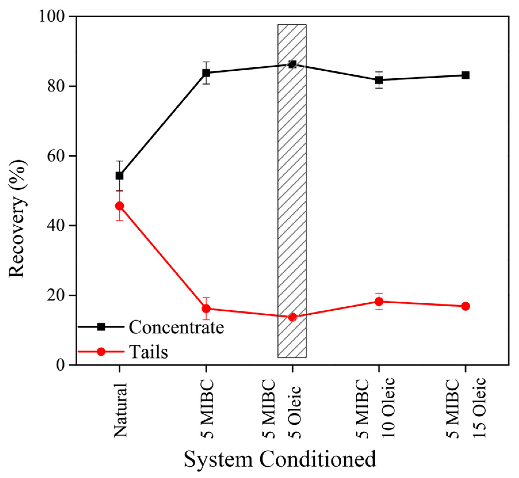
Figure 1 shows the recovery of sample M1 in the concentrate zone and the tails zone after the reverse froth flotation process; the process was performed twice on different dates to compare the obtained results; error bars in Figure 1 show the deviation in the average recovery results. Prior to the froth flotation process, a physical separation of the feed material using a manual panning technique allowed us to determine the weight of MF and NMF in the feed material to be 10.32 wt.% and 89.68 wt.%, respectively. Figure 1 shows that during the reverse froth flotation process, an evident separation of fractions was obtained under the different tested conditions. When pulp without any dosage of frother or collector was used, a recovery of 55–45% was obtained in the concentrate and tails, respectively. However, when the pulp is conditioned with 5 ppm MIBC frother [20], the separation obtained is closer to 80–20% in the concentrate and tails, respectively. When, in addition to the frother reagent, the pulp is conditioned with OA collector, the separation is further improved, reaching 87–13, 81–19, and 83–17% in the concentrate and tails, respectively, for the different dosages of collector used: 5, 10, and 15 g/ton of OA. The results obtained with 5 ppm MIBC plus 5 g/ton OA are in accordance with some researchers who reported that the quantity of metals in fine particles is close to 10 wt.% [9,11]; the shaded area in Figure 1 corresponds to the sample with better product separation i.e., 87–13% in the concentrate and tails, respectively; and this product was used in the next concentration process.
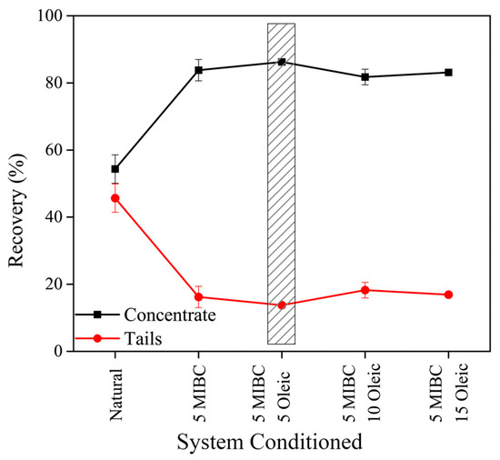
Figure 1.
Recovery material as a function of the system conditioned in the flotation column.
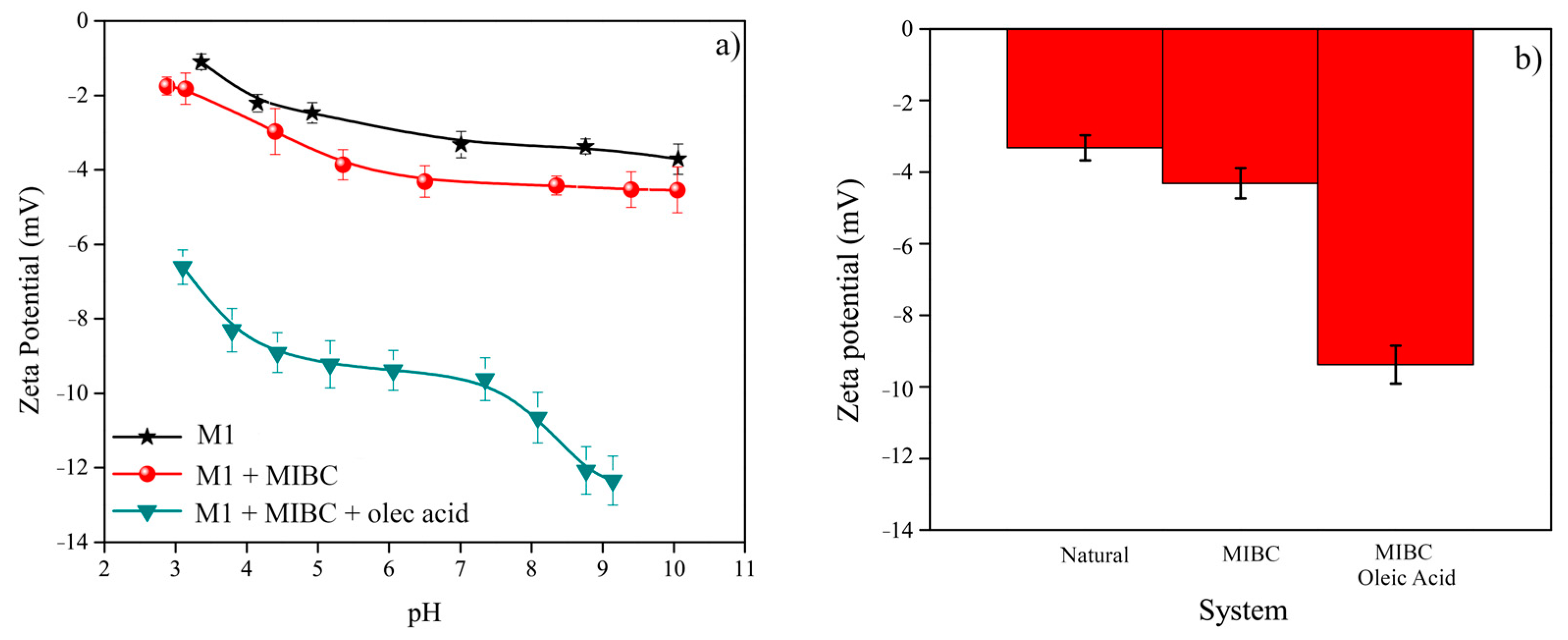
High recoveries are obtained due to the negative zeta potential of the NMF particles in the pulp. Figure 2a presents the zeta potential of the particles in sample M1 as a function of the pH of the pulp without chemical reagents, the pulp modified with MIBC, and the pulp modified with MIBC plus OA. At the pH analyzed, the zeta potential was negative for all three systems. At lower pH, the zeta potential tends toward positive values, showing the tendency of silicon [22]; silicon is one of the main components in fiberglass that comprises the PCBs as reported by [1]. When the pulp is conditioned, the zeta potential has more negative values for both systems at the analyzed pH values. Figure 2b presents the zeta potential of the three systems at their natural pH; the negative zeta potential of the no-conditioned pulp decreases by 0.99 mV when the pulp is conditioned with MIBC, and in the MIBC plus OA pulp, the zeta potential decreases by 6.06 and 5.28 mV when compared to the natural and MIBC pulp conditions, respectively. This change in the zeta potential is attributed to the formation of oleate dimer ions ((RCOO)22−) at the pH employed, which are the functional species that interact with the nonmetallic fraction particles [24]. The change in the zeta potential indicates that the double layer of the NMF particles has been modified [25,26], allowing the nonmetallic fraction to become more hydrophobic.
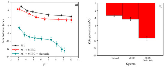
Figure 2.
Zeta potentials of the no-conditioned and conditioned systems (a) at different pH values, and (b) at natural pH for the three systems analyzed.
When the pulp is conditioned with the abovementioned chemical reagents, the particles are attracted to the polar end of the MIBC surfactant as well as to the headgroups of the OA and ascend attached to the air bubbles to the concentrate zone. Additionally, surfactants stabilize the air bubbles, preventing coalescence [25,27] and allowing their load to remain attached to the bubbles as they reach the concentrate zone. A separation of 87% of the nonmetallic material and 13% of the metallic fraction indicates a very good separation process. Despite these high recovery values obtained with the use of MIBC and OA, a few metallic fraction particles may still be present in the concentrate zone, as these particles might become trapped at the Plateau borders and vertices, channels that are formed where three lamellae meet forming an angle of 120°, generating a mechanical drag effect which reduces the overall yield of the metallic fraction, increasing the resulting density in the concentrate and decreasing the resulting density in the tails, since some metallic particles are separated into the wrong zone, a condition that is more evident at higher OA contents, indicating an overdosage of the pulp. Additionally, during the froth flotation process, the lamella separating the air bubbles contains selectively attached hydrophobic particles; if some lamellae fail, bubbles coalesce within the froth or bubbles burst on the surface, which releases the previously attached hydrophobic particles into the Plateau borders and vertices, which contain a slurry of liquid and free-moving particles, where they attempt to attach to new air bubbles; however, some particles cannot be attached and drop back while traveling to the tails zone [19].
From Figure 1 and Figure 2, it is evident that the dosage of chemical reagents into the pulp of water and fine particles increases the floatability of the nonmetallic fractions, generating a better separation of the fractions present in the pulp. When MIBC is dispersed into the pulp, the water dipoles easily associate with the polar group of the surfactant; on the other hand, the MIBC frother’s nonpolar group has air affinity, which results in the generation of air bubbles with the nonpolar group on the air surface, while the polar group remains oriented toward the water, stabilizing the air bubble and preventing undesirable froth bursting. The change in the air bubble size is explained by the effect of the MIBC that acts as a frother and as a collector, controlling the bubble coalescence and improving its stability in the froth flotation column as reported by [20,27].
Since the polar group of the MIBC surfactant is oriented toward the water, the electrically charged particles are attached to the dipoles of the chemical reagents, allowing the air bubbles to retain more hydrophobic material on their surface. This effect is due to the affinity attraction between the NMF particles and the polar end of the frother as described by [25].
When a fatty acid collector such as OA is dispersed into the pulp, it interacts in the solid–water interface in a complex process that involves several intermolecular forces acting in the water–air interface: there is an ion–dipole interaction that causes the headgroup to bind to water at the air–water interface; there is also a dipole–dipole interaction between the two polar ester functional groups in the collector and the water; an electrostatic repulsion exists between the positively charged headgroups that attract the nonmetallic fraction particles; and finally, there are hydrophobic interactions that keep the hydrophobic tails of the collector pointing toward the air bubble. These interaction forces allow the NMF particles to attach to the headgroups of the OA while the hydrophobic tail groups remain at the air bubble [28,29,30].
Table 1 shows the density values of the different products obtained from the reverse froth flotation process in a flotation column. The density of the feed material has an average value of 2.23 g/cm3. The concentrate has the lowest density, with values as low as 1.93 g/cm3, while the tails have the highest density with values as high as 4.39 g/cm3. These density values indicate that there is good separation of the different fractions present in the fine-particle material after the reverse froth flotation process is performed. It is interesting to note that the use of MIBC as a frother allows one to obtain a fraction with high density in the tails zone, and with the use of MIBC plus OA as a collector, the density slightly increases, indicating an improvement in the separation process. When chemical reagents are used, the froth attaches more particles, and part of the metallic fraction can be trapped in the concentrate zone, slightly increasing the concentrate density and decreasing the tails density, as shown in Table 1.

Table 1.
Densities of the sample products obtained from reverse froth flotation.
Figure 3 presents scanning electron microscopy micrographs of the fractions obtained from the reverse froth flotation process in a flotation column. Figure 3a corresponds to the feed (M1) particles where needle-shaped particles of different sizes can be observed, some individually while others are observed as a cluster; this needle-shaped material corresponds to fiberglass, which is one of the main support components of PCBs. Additionally, in the micrograph, some rounded, bright particles can be seen; these are part of the metallic fraction and correspond to tin, silver, or lead, which are metals present in the solder used to join the different components with the copper tracks on the PCB. The tin– silver–lead alloys are commonly used solders, and when tin is cooled to subzero temperatures, it becomes a brittle material that, when hit by the blades during the crushing process, easily detaches from the PCBs and is reduced to very small sizes, hence its presence in fine particles [31]. Additionally, plate-shaped particles which are part of the copper conduction tracks, as well as some blurred particles which correspond to the bromide flame retardants present in the epoxy resin and in some of the PCB fiberglass were observed.

Figure 3.
SEM micrographs of the (a) feed (M1), (b) concentrate (M1-C), and (c) tails (M1-T) products, after the froth flotation process in a flotation column.
Figure 3b corresponds to the concentrate (M1-C) particles, and its overall appearance is very similar to that of Figure 3a; fiberglass and resin are the predominant particles present in the concentrate, copper particles are no longer present, and only a few solder particles, which were probably trapped at the Plateau borders and vertices and dragged toward the concentrate zone, can be seen. The scarce quantity of metallic particles present in the concentrate is an indication that a good separation of fractions can be obtained using reverse froth flotation in a flotation column.
Figure 3c shows a micrograph of the tails (M1-T) particles, where some irregular rounded particles corresponding to the tin, silver, and lead solder material can be observed, as well as plate-shaped particles rich in copper, faceted particles rich in nickel, and particles that exhibit brittle fracture and a smooth flat surface throughout the material, corresponding to the ceramic barium titanate, a compound used in certain electronic components; these materials were confirmed by EDS analysis of the SEM samples. All of the mentioned materials have high densities, tin 7.45 g/cm3, silver 10.49 g/cm3, lead 11.34 g/cm3, copper 8.94 g/cm3, nickel 8.90 g/cm3, and barium titanate 5.92 g/cm3, and therefore remain in the tailing zone [32,33]. Some other types of crystalline material may be present in the tails fraction but are not detected by EDS analysis.
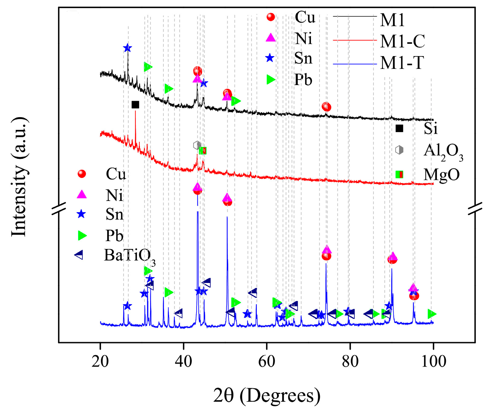
Figure 4 presents X-ray diffraction patterns of the material obtained after the separation of the PCB particles. The feed (M1) and concentrate (M1-C) spectra show, at low 2θ angles, a camel-like peak, which is a typical shape, of the amorphous materials, indicating the presence of high amounts of fiberglass and brominated resin which comprise the PCBs that support the electronic components [10]. Additionally, some defined peaks can be observed, corresponding to silicon from the integrated chips mounted on the raw PCBs, which are easily pulverized due to their brittleness during the comminution process and, as a result, are present at the corresponding fine particle sizes; and for aluminum oxide and magnesium oxide, these two elements are part of the fiberglass composition; the feed spectrum presents more well-defined peaks than the concentrate spectrum, indicating that the crystalline fraction was separated from the nonmetallic fraction after the froth flotation process. On the other hand, the tails (M1-T) spectrum presents only well-defined peaks with high intensities, indicating the presence of high quantities of crystalline materials.
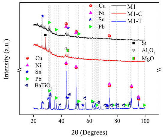
Figure 4.
XRD patterns of PCB particles in the feed (M1), concentrate (M1-C), and tails (M1-T) products.
The tails fraction XRD pattern presents several well-defined peaks, which correspond to lead, tin, copper, nickel, and BaTiO3, among others; some of these materials were not detected in the feed material analysis due to their small amount in the mixture of PCB particles; however, once the NMF was removed and the tails products was analyzed, these materials had a higher concentration and could be detected by the X-ray diffraction equipment. A small amount of NMF is present in the tails product, and since it is amorphous in nature, this fraction is not detected in the XRD pattern or is interpreted as noise in the generated spectra. The Rietveld method analysis of the X-ray diffraction patterns indicates that, in the feed material, 10.40% of the phases are crystalline, while the remaining material corresponds to the NMF, which is amorphous in nature. The reverse froth flotation process with a pulp modified with 5 ppm MIBC plus 5 g/ton OA results in a separation of 86.12–13.88% in the concentrate and tails, respectively; taking into account that, as mentioned earlier, the tails section retains some of the NMF, this result is consistent with the XRD analysis of the tails as well as with the physical, manual panning, separation of the MF and NMF that confirms a value of the amount of metals of 10.32% and nonmetals of 89.68%. This value is also in concordance with what some authors state, that approximately 10 wt.% of the metallic fraction is present at the corresponding fine particle sizes [18].
2.2.2. Magnetic Concentration
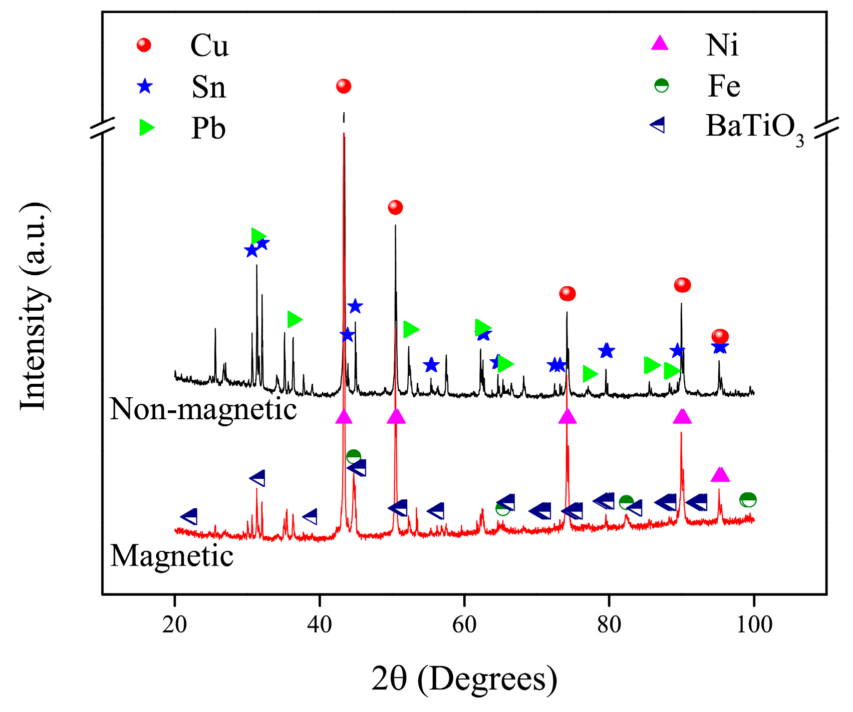
The resulting tails product, metallic fraction, was subject to a further separation process that was performed employing a magnetic concentrator. Figure 5 presents the X-ray diffraction patterns of both the magnetic (M1-M) and nonmagnetic (M1-NM) products. Nickel and iron, ferromagnetic metallic elements, are the principal metals recovered in the magnetic fraction; nevertheless, a small quantity of these metals may be left in the nonmagnetic fraction. On the other hand, silver, copper, tin, and lead, paramagnetic or diamagnetic metallic elements, were separated in the nonmagnetic fraction, although some of these metals may also be present in the magnetic fraction. Complete separation of fractions is not achieved and it could be due to some particles getting tramped with some other particles and forced to move along with them into the wrong fraction [34]. Some materials are present in proportions that are too scarce to be detected by the XRD equipment. As seen from the XRD analysis, the crystalline materials are mostly metallic materials, and the only ceramic material that was quantified in the tails product is barium titanate, which is a dielectric material that has a high permittivity [32].
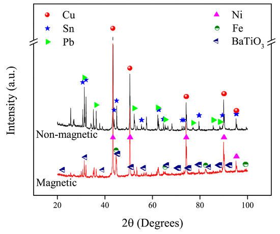
Figure 5.
XRD patterns of PCB particles in the magnetic and nonmagnetic products.
Based on the information analyzed in the figures and tables above, it can be seen that the recovery of fractions in the flotation column can reach values in the range of 87–13% in the concentrate and tails product, respectively. The vast majority of the material recovered in the concentrate corresponds to the nonmetallic fraction with only 0.37% corresponding to crystalline material; out of the 13% recovered in tails zone, 10.40% corresponds to metallic particles, which implies that the remaining 2.60% of the material found in the tails section is nonmetallic fraction, which is mixed with the metallic fraction and not detected by the XRD analysis. Considering that some authors state that up to 10% by weight of metals can be present in fine particles [11,18], the obtained concentration of metals is quite high and it is consistent with the results presented by [11].
Since silver is not detected by X-ray diffraction, quantitative analysis of the sample M1 before and after the silver concentration process was carried out employing atomic absorption spectrometry. The silver content in the sample M1 is 20 g/ton; after the concentration processes the silver grade increases to 1660 g/ton, indicating that this process is a good option for the concentration of silver from the fine particles of PCBs. Silver recovery obtained after employing the process here proposed is of 74.5%. Silver recovery of 86% has been reported by [7] employing different steps of roasting and leaching on the PCBs; the process here employed is greener and faster, and generates silver concentration similar to that reported by other researches.
This study confirmed that the concentration of silver as well as other valuable materials from fine PCB particles can be attained using a reverse froth flotation process in a flotation column, followed by a magnetic separation of the tails product; the quantity of silver recovered is very high, similar to the values reported in the literature. For the metallic fraction, a subsequent separation process, such as lixiviation, may be conducted to selectively obtain valuable metals; for the nonmetallic fraction, a polymer matrix composite may be conformed to take advantage of the anti-flame properties of the bromide products found in this fraction [35].
3. Materials and Methods
3.1. Silver Concentration
With the purpose of developing a silver concentration process, it was necessary to acquire printed circuit boards; these PCBs were conditioned to the comminution process to obtain the sample M1 particles. Figure 6 presents the flowsheet employed to obtain the PCB particles and the raw material for the research here analyzed.

Figure 6.
Flowsheet of the comminution process followed to obtain the sample M1.
The following sections preset the methodology used to concentrate the silver, despite other metals being concentrated.
3.1.1. Sample M1 Obtaining
The concentration of metals consisted first in a reverse froth flotation in a flotation column process, followed by a magnetic separation process of the tails products. The raw material, labeled Sample M1, was obtained after the comminution of arcade videogames’ PCBs obtained from arcade machines in the Estado de México, México. EDS analysis on a JEOL JSM 6610LV microscope (Tokyo, Japan), of the PCBs shows the presence of Cu, Ni, Pb, Sn, Ti, Ba, Fe, Al, Mg, Si, and Br, in different proportion; also, other elements are present in amounts too small to be detected by the equipment.
The crushing process was performed inside an atmospheric control chamber to trap fine particles as well as dust. The resulting generated PCB particles were screened using sieving meshes, and the particles that passed through the 60 mesh were chosen for the purpose of this study. A detailed procedure of the comminution process is presented by some of the authors [1]. Sample M1 material has a silver content of 0.002%.
3.1.2. Silver Concentration Process
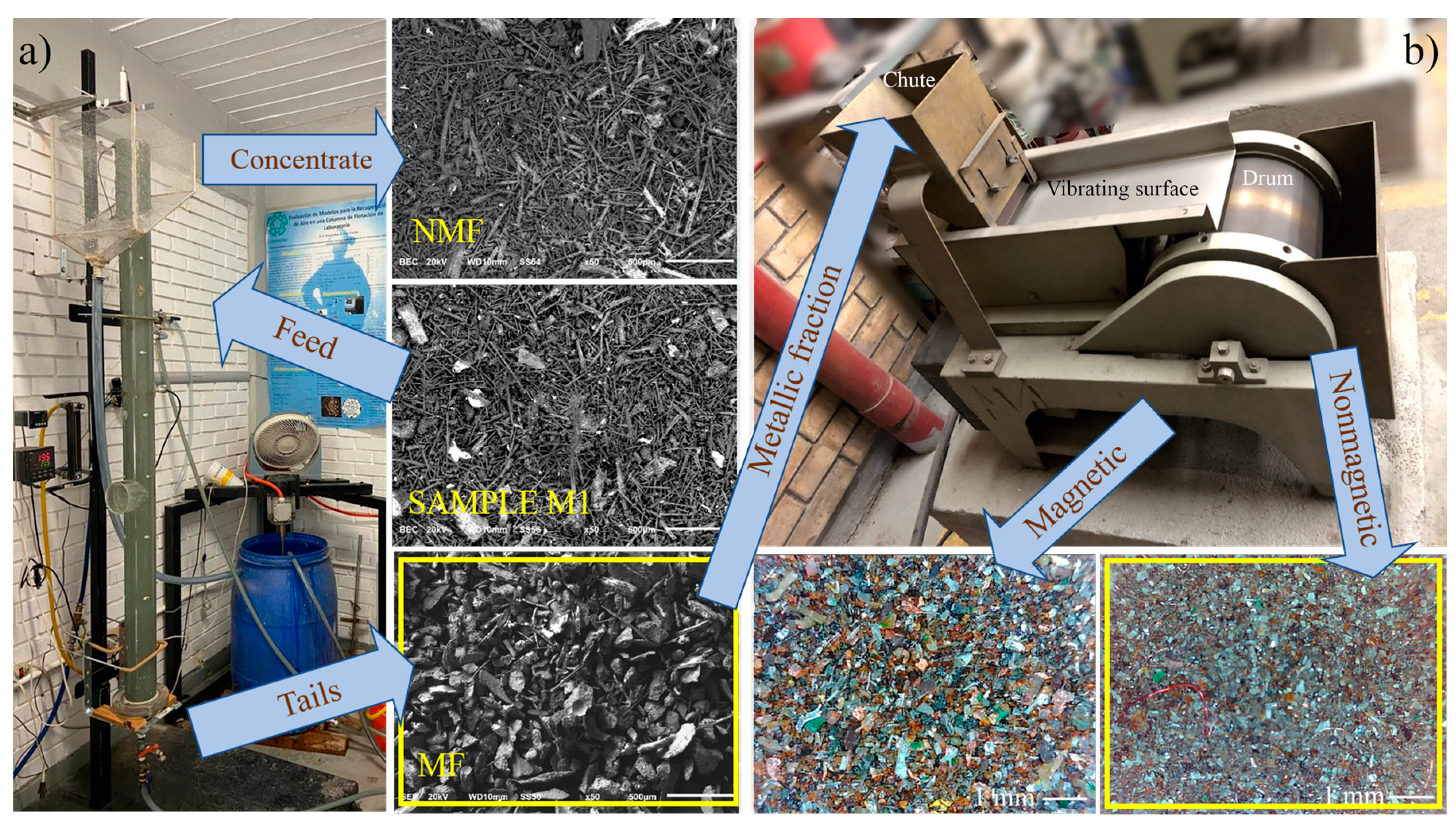
Figure 7 shows the representation of the methodology employed for the concentration of silver [36]. Figure 7a presents the froth flotation column. The process for the concentration of silver starts with the separation of the sample M1 into MF and NMF using reverse froth flotation employing a laboratory flotation column with 250 cm length and 9.5 cm diameter with a control loop to regulate the froth depth. The pulp was prepared by mixing the sample M1 particles with water, maintaining a solid content of 1.25 wt.%. As the process started, the superficial air velocity (Jg) in the flotation column was set at 0.20 cm/s. After 15 min of stabilization, the pulp was sampled in the following order: concentrate rate, tails rate and, finally, feed rate, in order to avoid any process disturbance. The first sample was taken from the pulp without any reagent; afterwards, the pulp was modified with chemical reagents and the process was repeated after each modification. Extra samples were taken from the pulp conditioned with 5 ppm MIBC frother, followed by samples taken from the pulp modified with 5 ppm MIBC plus 5, 10, and 15 g/ton OA collector. The previously described parameters correspond to the conditions that generated better results in the separation process with a pulp of water and 250 µm particles, without any chemical reagent employed. The process procedure is presented by some of the authors [1,20].
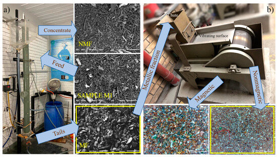
Figure 7.
Equipment employed for the separation of fractions in sample M1, (a) reverse froth flotation, and (b) magnetic separation.
Figure 7b presents the magnetic concentrator. The tails product obtained from the froth flotation process was further concentrated into magnetic and nonmagnetic fractions using a laboratory Humboldt Wedag magnetic concentrator from KHD Humboldt Wedag International AG (Cologne, Germany). The tails particles were fed into a chute that distributes the fine particles in a homogeneous flow over a vibrating surface at the end of which the particles fall into a container; a magnetic cylinder located at the edge of this surface attracts all the magnetic particles, which are then collected into a separate container.
3.2. Characterization
Sample M1 particles were characterized by Zeta potential analysis in a zeta-meter 3.0+, operated at 100 V. The density of the fractions was determined using a graduated 25-mL pycnometer with ethyl alcohol as the liquid media to ensure that the fine particles would sink in the pycnometer instead of floating. Five different measurements were performed to obtain a representative density value for each analyzed condition. Microstructural characterization was performed using a scanning electron microscope (SEM) on a JEOL JSM 6610LV microscope operated at 20 kV. The chemical analyses were determined by energy dispersive spectroscopy (EDS) using an Oxford Inca X-ray energy dispersive spectrometer attached to the microscope system. Additionally, a Dino-Lite digital microscope was employed to obtain micrographs of the concentrate, tails, and feed material. Structural characterization was carried out by X-ray diffraction (XRD) in a Panalytical X’Pert PRO diffractometer, from Malvern Panalytical, Malvern, UK, with a Cu Kα source (λ = 0.15406 nm) operated at 40 kV and 25 mA in the 2θ range of 20–100°; the step size and collection time were 0.02° and 2 s, respectively. Chemical analysis of the dissolved sample products for silver quantification was carried out by atomic absorption using a Perkin Elmer PinAAcle 900T System with a Syngistix V3 software.
4. Conclusions
Comminution of PCBs produces a wide range of particle sizes, including fine particles and dust, considered as non-desirable; however, these particles have different metals which can be concentrated employing a reverse froth flotation process followed by a magnetic separation process.
A reverse froth flotation process in a flotation column was performed to concentrate the metallic and nonmetallic fractions, starting from particles with sizes smaller than 250 µm obtained from arcade videogame PCBs crushed in one pass on a blade crusher machine.
The best separation of fractions was obtained when the pulp was conditioned with 5 ppm MIBC plus 5 g/ton Oleic Acid, reaching a separation of 13.87–86.13% of the metallic and nonmetallic fractions, respectively. At higher dosages, these environmentally friendly reagents increase the separation of fractions by getting the hydrophilic particles trapped between the hydrophobic particles, reducing the overall concentration of metals.
Magnetic separation of the tails products improved the final silver grade from 20 g/ton to 1660 g/ton, a recovery of 74.5%.
74.5% of silver concentration was achieved without the need of roasting or leaching the PCBs.
The improvement in the separation of fractions by using MIBC and OA reagents is considered environmentally friendly since these reagents rapidly degrade.
The correct practice for the recycling of EOL-EEEs must be economically reasonable while also taking care of the environment and the personnel who perform the recycling process.
Author Contributions
Conceptualization, R.F.-C. and R.H.E.-R.; Formal analysis, R.F.-C., R.H.E.-R., M.R.-R., D.M.-C. and A.M.-L.; Funding acquisition, R.H.E.-R.; Investigation, R.F.-C., R.H.E.-R., M.R.-R., D.M.-C. and A.M.-L.; Methodology, R.F.-C., R.H.E.-R., M.R.-R., D.M.-C. and A.M.-L.; Project administration, R.H.E.-R.; Writing—original draft, R.F.-C.; Writing—review & editing, R.H.E.-R. and A.M.-L. All authors have read and agreed to the published version of the manuscript.
Funding
This study was funded by Tecnológico Nacional de México grant number 16982.23-P.
Data Availability Statement
The original data presented in the study are openly available in the “E-waste” 2022 Mendeley Data, v2 repository, https://doi.org/10.17632/4wtbk3yk4f.2.
Acknowledgments
The authors are grateful to D. Vázquez-Obregón, G. Flores-Campos and J.J. Zamora-García for their technical assistance.
Conflicts of Interest
The authors declare no conflict of interests.
References
- Estrada-Ruiz, R.H.; Flores-Campos, R.; Gámez-Altamirano, H.A.; Velarde-Sánchez, E.J. Separation of the metallic and non-metallic fraction from printed circuit boards employing green technology. J. Hazard. Mater. 2016, 311, 91–99. [Google Scholar] [CrossRef] [PubMed]
- Stuhlpfarrer, P.; Luidold, S.; Antrekowitsch, H. Recycling of waste printed circuit boards with simultaneous enrichment of special metals by using alkaline melts: A green and strategically advantageous solution. J. Hazard. Mater. 2016, 307, 17–25. [Google Scholar] [CrossRef] [PubMed]
- Büyükbay, B.; Ciliz, N.; Goren, G.E.; Mammadov, A. Cleaner production application as a sustainable production strategy, in a Turkish Printed Circuit Board Plant. Resour. Conserv. Recycl. 2010, 54, 744–751. [Google Scholar] [CrossRef]
- Duan, H.; Hou, K.; Li, J.; Zhu, X. Examining the technology acceptance for dismantling of waste printed circuit boards in light of recycling and environmental concerns. J. Environ. Manag. 2011, 92, 392–399. [Google Scholar] [CrossRef] [PubMed]
- Yamane, L.H.; De Moraes, V.T.; Crocce, D.; Espinosa, R.; Alberto, J.; Tenório, S. Recycling of WEEE: Characterization of spent printed circuit boards from mobile phones and computers. Waste Manag. 2011, 31, 2553–2558. [Google Scholar] [CrossRef]
- Guo, C.; Wang, H.; Liang, W.; Fu, J.; Yi, X. Liberation characteristic and physical separation of printed circuit board (PCB). Waste Manag. 2011, 31, 2161–2166. [Google Scholar] [CrossRef]
- Panda, R.; Mishra, S.; Kishore, K.; Bhaskar, T. A closed loop recycling strategy for sustainable recovery of group 11 metals (Cu, Au, and Ag) from waste PCBs: An amalgamation of low-temperature NH4Cl roasting, HCl leaching and cementation. Sustain. Mater. Technol. 2023, 37, e00652. [Google Scholar] [CrossRef]
- Islam, M.T.; Iyer-Raniga, U. Life cycle assessment of e-waste management system in Australia: Case of waste printed circuit board (PCB). J. Clean. Prod. 2023, 418, 138082. [Google Scholar] [CrossRef]
- Das, S.K.; Ellamparuthy, G.; Kundu, T.; Ghosh, M.K.; Angadi, S.I. Critical analysis of metallic and non-metallic fractions in the flotation of waste printed circuit boards. Powder Technol. 2021, 389, 450–459. [Google Scholar] [CrossRef]
- Ali, L.; Mousa, H.A.; Al-Harahsheh, M.; Al-Zuhair, S.; Abu-Jdayil, B.; Al-Marzouqi, M.; Altarawneh, M. Removal of Bromine from the non-metallic fraction in printed circuit board via its Co-pyrolysis with alumina. Waste Manag. 2022, 137, 283–293. [Google Scholar] [CrossRef]
- Kumar, V.; Chun Lee, J.; Jeong, J.; Jha, M.K.; Kim, B.S.; Singh, R. Recycling of printed circuit boards (PCBs) to generate enriched rare metal concentrate. J. Ind. Eng. Chem. 2015, 21, 805–813. [Google Scholar] [CrossRef]
- Liu, R.; Ma, S.; Li, G.; Yu, Y.; An, T. Comparing pollution patterns and human exposure to atmospheric PBDEs and PCBs emitted from different e-waste dismantling processes. J. Hazard. Mater. 2019, 369, 142–149. [Google Scholar] [CrossRef] [PubMed]
- Cucchiella, F.; D’Adamo, I.; Lenny Koh, S.C.; Rosa, P. A profitability assessment of European recycling processes treating printed circuit boards from waste electrical and electronic equipments. Renew. Sustain. Energy Rev. 2016, 64, 749–760. [Google Scholar] [CrossRef]
- Kelly, E.; Spottiswood, D. Introduction to Mineral Processing; John Wiley & Sons Inc.: New York, NY, USA, 1982. [Google Scholar]
- Zhu, P.; Chen, Y.; Wang, L.Y.; Zhou, M.; Zhou, J. The separation of waste printed circuit board by dissolving bromine epoxy resin using organic solvent. Waste Manag. 2013, 33, 484–488. [Google Scholar] [CrossRef]
- Zhu, P.; Chen, Y.; Wang, L.Y.; Qian, G.Y.; Zhou, M.; Zhou, J. A new technology for separation and recovery of materials from waste printed circuit boards by dissolving bromine epoxy resins using ionic liquid. J. Hazard. Mater. 2012, 239–240, 270–278. [Google Scholar] [CrossRef]
- Magoda, K.; Nomngongo, P.N.; Mekuto, L. Two-Step Bio-Dissolution of Metals from Printed Circuit Boards Using Acidophilic Iron- and Sulfur-Oxidizing Mesophiles. Recycling 2024, 9, 6. [Google Scholar] [CrossRef]
- Bachér, J.; Rintala, L.; Horttanainen, M. The effect of crusher type on printed circuit board assemblies’ liberation and dust generation from waste mobile phones. Miner. Eng. 2022, 185, 107674. [Google Scholar] [CrossRef]
- Fuerstenau, M.C.; Jameson, G.J.; Yoon, R.H. Froth Flotation: A Century of Innovation; SME: Englewood, CO, USA, 2007. [Google Scholar]
- Flores-Campos, R.; Estrada-Ruiz, R.H.; Velarde-Sánchez, E.J. Study of the physicochemical effects on the separation of the non-metallic fraction from printed circuit boards by inverse flotation. Waste Manag. 2017, 69, 400–406. [Google Scholar] [CrossRef]
- Yukselen-Aksoy, Y.; Kaya, A. A study of factors affecting on the zeta potential of kaolinite and quartz powder. Environ. Earth Sci. 2011, 62, 697–705. [Google Scholar] [CrossRef]
- Kim, J.; Nason, J.A.; Lawler, D.F. Zeta potential distributions in particle treatment processes. J. Water Supply Res. Technol. 2006, 55, 461–470. [Google Scholar] [CrossRef]
- Olson, E. Zeta Potential and Colloid Chemistry. J. GXP Compliance 2012, 16, 81–96. [Google Scholar]
- Fan, G.; Wang, L.; Cao, Y.; Li, C. Collecting Agent–Mineral Interactions in the Reverse Flotation of Iron Ore: A Brief Review. Minerals 2020, 10, 681. [Google Scholar] [CrossRef]
- Nguyen, K.T.; Shahir, A.A.; Nguyen, A.V. Probing the Molecular Orientation of Methyl Isobutyl Carbinol at the Air–Water Interface. Surfactants Deterg. 2017, 20, 969–976. [Google Scholar] [CrossRef]
- Phan, C.M.; Nakahara, H.; Shibata, O.; Moroi, Y.; Le, T.N.; Ang, H.M. Surface Potential of Methyl Isobutyl Carbinol Adsorption Layer at the Air/Water Interface Surface potential of methyl isobutyl carbinol adsorption layer at the air/water interface. J. Phys. Chem. B 2012, 116, 980–986. [Google Scholar] [CrossRef]
- Pattanaik, A.; Venugopal, A. Role of Surfactants in Mineral Processing: An Overview. In Surfactants and Detergents; Dutta, A.K., Ed.; IntechOpen: London, UK, 2019; Volume 1, pp. 1–17. [Google Scholar] [CrossRef]
- Cook, B.K.; Gibson, C.E. A Review of Fatty Acid Collectors: Implications for Spodumene Flotation. Minerals 2023, 13, 212. [Google Scholar] [CrossRef]
- Yu, F.; Wang, Y.; Zhang, L.; Zhu, G. Role of oleic acid ionic–molecular complexes in the flotation of spodumene. Miner. Eng. 2015, 71, 7–12. [Google Scholar] [CrossRef]
- Bhadani, A.; Iwabata, K.; Sakai, K.; Koura, S.; Sakai, H.; Abe, M. Sustainable oleic and stearic acid based biodegradable surfactants. RSC Adv. 2017, 7, 10433–10442. [Google Scholar] [CrossRef]
- Avner, S.H.; Haen, J.L.E.; Mejía, G.B. Introducción a la Metalurgia Física; McGraw-Hill: México, México, 1979. [Google Scholar]
- Jamil, M.S.; Saputro, K.E.; Noviyanto, A.; Widayatno, W.B.; Wismogroho, A.S.; Amal, M.I.; Rochman, N.T.; Nishimura, T. Dense and fine-grained barium titanate prepared by spark plasma sintering. J. Phys. Conf. Ser. 2019, 1191, 012039. [Google Scholar] [CrossRef]
- Gale, W.F. Smithells Metals Reference Book, 8th ed.; Elsevier/ASM International: Boston, MA, USA, 2004. [Google Scholar]
- Yoo, J.M.; Jeong, J.; Yoo, K.; Lee, J.; Kim, W. Enrichment of the metallic components from waste printed circuit boards by a mechanical separation process using a stamp mill. Waste Manag. 2009, 29, 1132–1137. [Google Scholar] [CrossRef]
- Flores-Campos, R.; Deaquino-Lara, R.; Rodríguez-Reyes, M.; Martínez-Sánchez, R.; Estrada-Ruiz, R.H. The Use of Nonmetallic Fraction Particles with the Double Purpose of Increasing the Mechanical Properties of Low-Density Polyethylene Composite and Reducing the Pollution Associated with the Recycling of Metals from E-Waste. Recycling 2024, 9, 56. [Google Scholar] [CrossRef]
- Estrada-Ruiz, R.H.; Flores-Campos, R. E-Waste. Mendeley Data, v2. 2022. Available online: https://data.mendeley.com/datasets/4wtbk3yk4f/2 (accessed on 1 April 2022). [CrossRef]
Disclaimer/Publisher’s Note: The statements, opinions and data contained in all publications are solely those of the individual author(s) and contributor(s) and not of MDPI and/or the editor(s). MDPI and/or the editor(s) disclaim responsibility for any injury to people or property resulting from any ideas, methods, instructions or products referred to in the content. |
© 2024 by the authors. Licensee MDPI, Basel, Switzerland. This article is an open access article distributed under the terms and conditions of the Creative Commons Attribution (CC BY) license (https://creativecommons.org/licenses/by/4.0/).

