Article

An Innovative Magnetic Density Separation Process for Sorting Granular Solid Wastes

1
Resource & Recycling, Department of Engineering Structures, Faculty of Civil Engineering and Geosciences, Delft University of Technology, 2628 CN Delft, The Netherlands
2
Faculty of Science and Technology, University of Twente, 7522 NB Enschede, The Netherlands
*
Authors to whom correspondence should be addressed.
Recycling 2024, 9(3), 48; https://doi.org/10.3390/recycling9030048
Submission received: 10 April 2024 / Revised: 16 May 2024 / Accepted: 22 May 2024 / Published: 3 June 2024

Abstract

:
Solid waste sorting is an important pre-treatment in recycling to improve the efficiency of material recovery and reduce costs. Motivated by the PEACOC project on metal recovery from solid wastes, an innovative magnetic density separation (MDS) process has been developed for solid waste sorting. It has intrinsic advantages over conventional gravity separation technologies and the previously industrialized MDS process. The new MDS process applies an inclined planar magnet and a horizontal basin containing a static magnetic fluid as the separation medium. A particle sliding phenomenon is identified as a feature that could help the separation. Experiments have been carried out to demonstrate the role of the MDS in concentrating valuable metals in shredded PCBAs and reducing metallic contaminants in plastic fractions of shredded wires. A pilot scale facility is introduced to show the design to achieve continuous production and to reduce the consumption of ferrofluid.

1. Introduction

The amount of solid waste has been rapidly increasing worldwide, which is a risk to the environment [1]. From another perspective, solid waste is a source of recyclable materials such as metals and plastics, and recovery of the materials is important considering the global or local strain of different resources [2]. Processing municipal and industrial solid wastes has been attracting the attention of researchers working on developing and optimizing solid waste sorting technologies such as magnetic sorting, eddy current sorting, ballistic sorting, and gravity sorting [1,2,3]. Solid waste sorting helps concentrate or purify wanted substances and discard unwanted substances. This reduces the cost of subsequent processes and increases the efficiency of recovering wanted materials [4,5]. The final purpose is to ensure that the entire recycling process is efficient and profitable. As with mineral processing, solid waste sorting technologies utilize property differences between particles to separate them such as magnetism, conductivity, size, shape, and density differences. This work presents an innovative magnetic density separation (MDS) process which should be considered as a gravity sorting technology since it separates particles by their density differences. It has several advantages over other gravity separation technologies, as well as over the previously industrialized MDS process developed by the same group [6]. The work was motivated by the PEACOC project of the European Union which aims to recover precious metals from several solid wastes. Wasted PCBAs are one of the main wastes to be processed and the innovative MDS process was intended to concentrate valuable metals within it. The process was also invented for the sorting of other solid wastes such as wasted wires to satisfy the industrial needs in the Netherlands. Except for solid waste sorting, the innovative MDS process could also be applied in other fields where there is a need to sort solid particles by density, such as in mineral processing.
In MDS, the feedstock is non-magnetic particles. A magnetic fluid under a gradient magnetic field is the separation medium. Magnetic fluid was invented in the 1960s; it is as a liquid colloid composed of a base liquid and suspended magnetic nanoparticles, meaning that it can be attracted by a magnet [7,8]. Later, it was found that the downward magnetic attraction on a magnetic fluid exerted by a magnet beneath the fluid resulted in an upward fluidmagnetic buoyancy on a non-magnetic particle in the fluid [9]. As a result, a particle with a density higher than the fluid density could float rather than sink. The fluidmagnetic buoyancy continuously increases as the particle in the fluid moves downward, i.e., closer to the magnet. Therefore, the particle dropped in the fluid may neither sink to the bottom nor float at the fluid surface, but instead suspend at a certain height where its gravity equals the sum of the fluidmagnetic buoyancy and the original buoyancy without a magnetic field. This allows the separation between particles with different densities since they suspend at different heights and allows the separation between multiple particle streams in one single process. The separation is called MDS and has been studied in the past decades [10,11,12] across a wide range of applications including resource recovery (car metals [13]; incinerator bottom ash [14,15]; WEEE [16]; plastics [17,18]), mineral processing (coal preparation [19]; diamond and precious metal enrichment [20,21,22]), and seed sorting [23].
MDS could be economically promising in solid waste sorting for resource recovery [24]. With the innovative planar magnet [25] and synthesis method of magnetic fluid [26], Peter Rem et al. successfully industrialized MDS for plastic sorting with a certain design of separation channel and feeding and collection systems [6]. The facilities have been applied by Umincorp in the Netherlands. In the separation channel [27], a magnetic fluid is continuously flowing horizontally and transporting fed particles through a laminator, a separation zone, and a collection zone in sequence. The laminator creates a laminar fluid flow for the separation zone. The separation zone is under a gradient magnetic field; thus, heavier particles form lower streams and lighter particles form higher streams. Splitters are used in the collection zone to split separated particle streams at different heights for collection. The above MDS process has some intrinsic limitations. Firstly, the throughput of this system depends on the fluid flow velocity because particles are conveyed by the fluid, but increasing the fluid velocity could cause more turbulence that may affect the separation accuracy in the separation zone. Corresponding studies were carried out to examine the turbulence effect [27,28,29] and it was suggested to design the structure carefully and control the fluid velocity. Secondly, if a particle entering the splitter zone has a dimension larger than the distance between two splitter walls (e.g., 2 cm), it may get stuck and then block subsequent particles.
The innovative MDS process presented in this work has corresponding intrinsic advantages over the above MDS process. Firstly, the new process applies a static magnetic fluid rather than a flowing fluid; thus, the process is no longer affected by turbulence. Particle motion is not driven by a fluid’s flow but by its gravity and fluidmagnetic buoyancy. Secondly, no splitters are used in the new process; thus, the process is no longer affected by particle jamming.
This article will introduce the principle of the new MDS process, illustrating how particles are driven in the magnetic fluid and how they are split without splitters. The advantages over existing gravity separation technologies will also be discussed. Then, an intrinsic particle sliding phenomenon will be illustrated both experimentally and numerically. Since the new process was developed as an advanced solid waste granular sorting technology, experiments on sorting shredded PCBAs and shredded wires will be shown and discussed. Lastly, a pilot-scale facility will be introduced to illustrate how to realize a continuous and economic industrial process.

2. Materials and Methods

2.1. Principle of the Innovative MDS

Figure 1 shows the principle of the new MDS process, where particle motion was simulated using LIGGGHTS [30]. The forces on one specific particle are also shown in the figure (the fluid drag force on the particle is not shown but was calculated in the simulation). The process applies a tilted magnet with a planar upper surface [25]. The field strength above the magnet decreases exponentially with the normal distance to the magnet [18]:
B = B 0 e π z / p
where B 0 is the field strength magnitude at the magnet surface, p is the pole size of the magnet, and z is the normal distance to the magnet. A basin with a horizontal bottom containing magnetic fluid is placed above the magnet. The fluidmagnetic buoyancy F m a g _ b u o y a n c y on the particle immersed in the fluid has the same magnitude but opposite direction as the magnetic attraction exerted by the magnet on the fluid displaced by the particle [18]:
F m a g _ b u o y a n c y = M V p π B 0 p e π z / p
where M is the magnetization of the fluid and V p is the volume of the particle. The gradient of the magnetic field is perpendicular to the magnet, so the particles with different densities dropped in the fluid would find their respective equilibrium positions along the normal direction to the magnet. The inclination of the magnet results in a horizontal component of F m a g _ b u o y a n c y on the particle which drives the particle forward (to the right side). Therefore, particles move both downward and forward along trajectories parallel to the magnet, then deposit on the basin bottom. The trajectories of heavier particles are closer to the magnet, while lighter particles are higher, so they move further before depositing on the basin bottom. Therefore, particles with different densities are distributed at different positions on the bottom. In practice, the deposited particles can be conveyed by a horizontal belt to be collected. The belt should lie on the basin bottom, moving along the perpendicular direction to the plane, as in Figure 1.
In some conventional gravity separation processes such as sedimentation, jigging, shaking tables, and hydrocyclones [31,32], particles are transported by liquid. The separation result depends not only on particle density, but also on particle size. Small but heavy particles may move together with light but large particles; thus, the separation between heavy and light particles may not be achieved. Therefore, it is suggested to first screen the feedstock into narrow-size fractions, especially when the feedstock contains particles with a wide-size distribution [24]. This means increasing the equipment, energy, and time consumption. The new MDS overcomes the above drawback because each particle can deposit to its equilibrium position immediately after it is dropped and keeps a constant distance from the magnet before it deposits on the bottom. The distance is determined only by its density. Heavy medium separation using a static heavy medium bath is the only conventional gravity separation technology that can also eliminate the effects of a particle’s size and shape [31]. However, the solution medium with a high density, such as Clerici solution (4.9 g/cm3), is expensive and toxic; thus, its application in processing large amounts of solid wastes is limited [24]. Slurry with suspended ferrosilicon or magnetite powder can be used as a heavier medium than the solution, which is cheaper and non-toxic. However, the process is not suitable for particles smaller than 12.5 mm or particles with close densities to the slurry [16,31], because in those cases, it is difficult for particles to settle down smoothly. In the innovative MDS process, particles deposit on the bottom within seconds after they are dropped, even if they are as small as 1 mm, because the particle is driven not only by gravity but also by the stronger fluidmagnetic buoyancy. Furthermore, the innovative MDS process allows multiple particle streams with different densities to be separated in one single process, which cannot be achieved in heavy medium separation. In summary, the innovative MDS process has unique advantages over conventional gravity separation technologies.

2.2. Particle Sliding Phenomenon

A particle sliding phenomenon was identified as a feature of the above MDS process. When a particle moving in the fluid along its inclined trajectory reaches the horizontal bottom of the basin, it slides forward rather than stopping immediately. The phenomenon was demonstrated both experimentally and numerically.

2.2.1. Experimental Demonstration

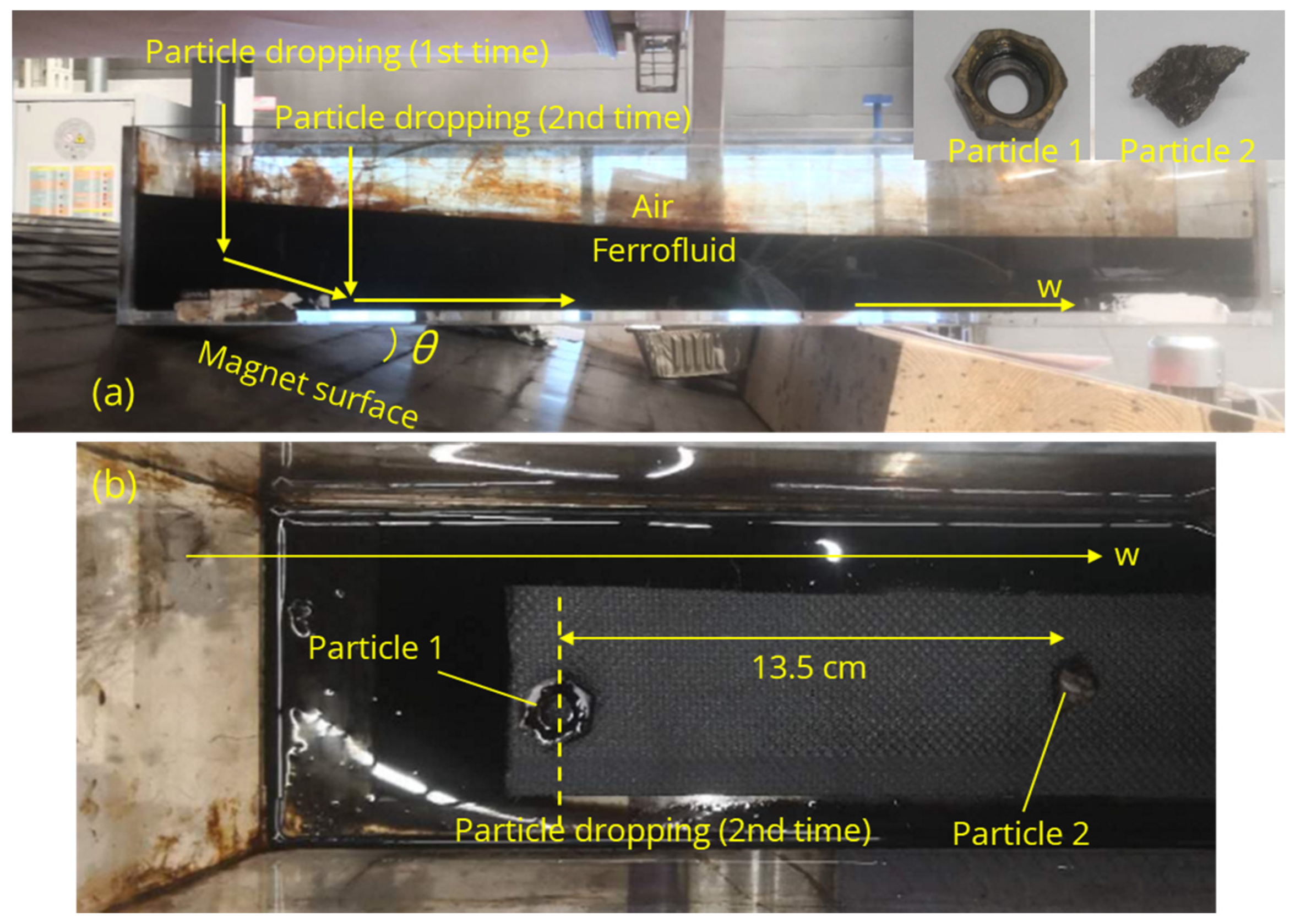
Figure 2a shows the experimental setup for the demonstration. A transparent container containing some black ferrofluid (produced by Umincorp in the Rotterdam, The Netherlands) was placed horizontally above the inclined permanent magnet. The ferrofluid is a magnetic fluid with nanomagnetite particles of 10 nm suspended in water, and some organic solvent was added to disperse the nanoparticles. It is notable that the fluid surface on the left was higher than the right because the left part of the fluid was closer to the magnet and, thus, was attracted more. Figure 2a also shows two particles that were dropped in the fluid. Particle 1 was brass and Particle 2 was aluminum. Some physical parameters related to the experiment are listed in Table 1.
Particle 2 was first dropped in the fluid from the left, corresponding to “Particle dropping (1st time)” in Figure 2a. The estimated dropping position on the w axis was close to the left edge of the container so that Particle 2 moved downward first and then followed the inclined trajectory until it reached the bottom. Note that if Particle 1 was dropped from the same position, it would not have an inclined trajectory but would directly sink to the bottom, because its density was too high considering the given magnetic field strength and fluid magnetization. It could not be levitated by the fluid, even if it was at the left bottom corner of the container where the fluidmagnetic buoyancy was the largest. The position on the w axis where Particle 2 first touched the bottom could not be directly observed because the fluid is so black that any particle in it is not visible. To obtain the position, a board was put in the fluid to stop Particle 2 on its path. The board surface was perpendicular to the inclined particle trajectory. After Particle 2 was stopped by the board, the fluid was slowly pumped out until Particle 2 appeared at the fluid surface; then, its position could be marked. By changing the position of the board on the w axis several times and repeating the dropping of Particle 2 and marking its position, the inclined trajectory of Particle 2 was marked and the position where it first touched the bottom was known. The position was then used as the position of the second dropping, corresponding to “Particle dropping (2nd time)” in Figure 2a. In the second dropping, both Particle 1 and Particle 2 were dropped. The role of Particle 1 was to mark the dropping position, as the dash line shows in Figure 2b. Figure 2b shows the final positions of the particles on the bottom after the second dropping and after the fluid was pumped out. Particle 2 was found to slide across 13.5 cm after it reached the bottom. It is interesting that, in the first dropping, the sliding distance of Particle 2 was also 13.5 cm. This indicates that the velocity of Particle 2 along + w when it first touched the bottom contributed very little to its sliding distance on the bottom.

2.2.2. Numerical Demonstration

The reason that Particle 2 was driven to slide on the bottom is numerically illustrated. Figure 3a shows the forces on Particle 2 sliding on the bottom. The orange dash arrow lines mark its trajectory. On the w axis, when the particle was at w = w 1 , the net force along the normal direction to the magnet was zero:
F gravity cos θ = F buoyancy cos θ + F mag_buoyancy
which is:
ρ p g V p cos θ = ρ g V p cos θ + M V p π B 0 p e π z / p
where z = w 1 sin θ . With the parameters in Table 1, w 1 can be calculated as 23 cm. When Particle 2 is sliding on the bottom, i.e., w = w 1 + w 2 , the vertical net force on the particle is zero:
F buoyancy + F normal + F mag_buoyancy cos θ = F gravity
Note that z = w 1 + w 2 sin θ . Assuming the sliding friction coefficient μ is 0.5, the sliding friction F sliding = μ F n o r m a l can be calculated with a given w 2 . Figure 3b shows the variations of F sliding and the horizontal component of F mag_buoyancy with w 2 . When w 2 = 0 , F sliding was much smaller than F mag_buoyancy sin θ . This indicates that Particle 2 was being accelerated along + w when it first touched the bottom, demonstrating the inevitability of the particle sliding phenomenon. In the case of Figure 3b, only after Particle 2 slides to w 2 = 0.09 m does it start to slow down.
The particle sliding phenomenon suggests a useful technique to improve the separation performance. For example, in the case of Figure 2b, if Particle 2 did not slide on the bottom, it would have the same final position as Particle 1 on the bottom. That means separation between them was not possible unless the fluid magnetization or the magnetic field strength was increased. However, with the particle sliding phenomenon, Particle 2 was 13.5 cm further than Particle 1 on the bottom. That distance was large enough for distinguishing two particle streams and separately collecting them. One can also choose to prevent particle sliding using cleats on the bottom. How to deal with the phenomenon depends on the specific engineering needs. It is suggested to further study the effects of particle-related parameters on sliding distance in future work.

2.3. MDS Experiments on Solid Waste Sorting

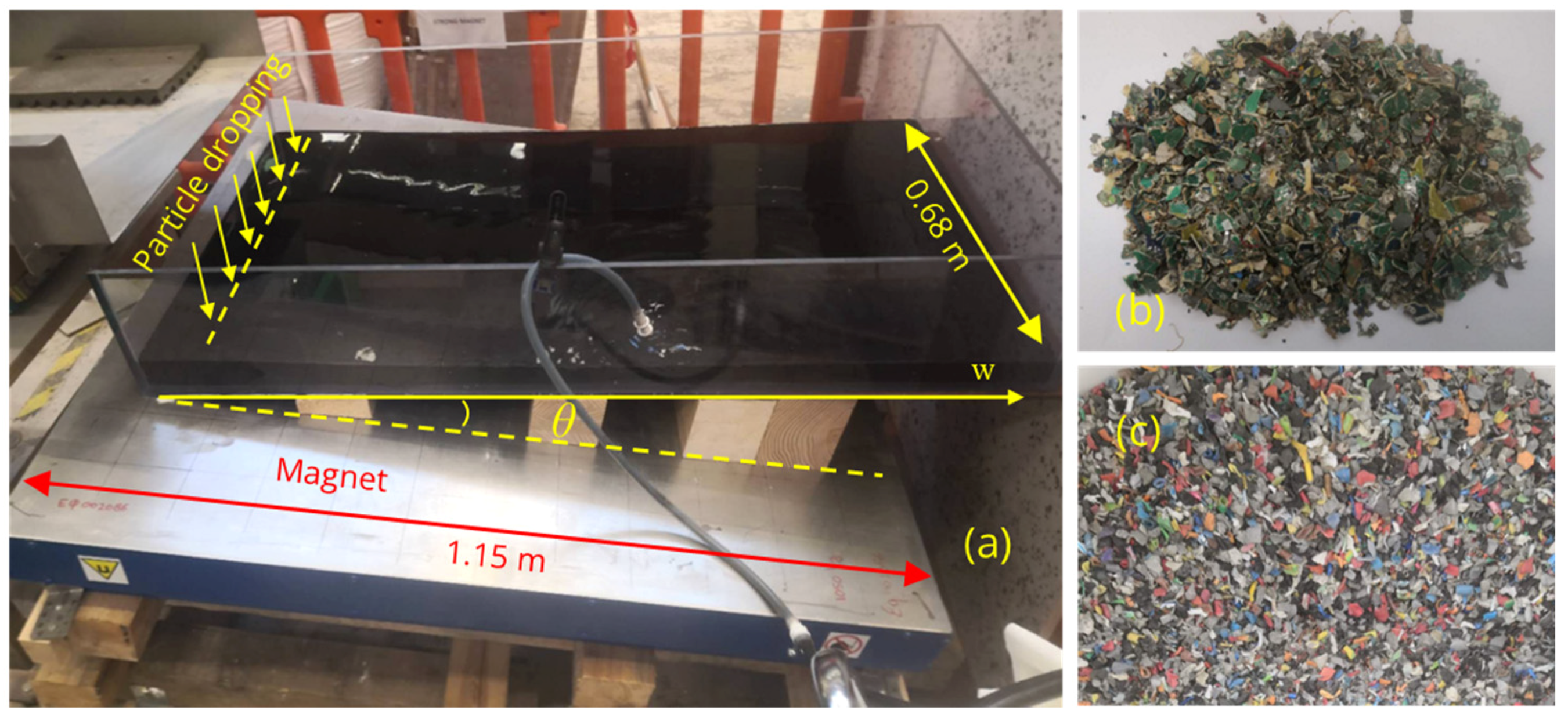
To demonstrate the effectiveness of the above MDS process in solid waste sorting, experiments were carried out to sort shredded PCBAs to concentrate valuable metals, and sort shredded wires to purify plastic fractions. Figure 4a shows the experimental setup. A transparent rectangular container was placed horizontally above the inclined magnet and was filled with ferrofluid using a pump. The magnet had a rectangular upper surface of 1.2 m × 1.15 m and its other physical parameters matched Table 1. The magnetization of the fluid was 2000 A/m. In the experiment, the feedstock scraps were dropped into the fluid close to the left edge of the container. The dropped scraps then moved in the fluid and deposited at different positions along the w axis on the bottom of the container. Scraps with higher densities were closer to the left side, while lighter scraps were further to the right.
Figure 4b shows the feedstock of shredded PCBAs. It was the fraction after removing foil scraps by wind sifting and removing magnetic scraps by magnetic sorting from the original shredded PCBAs. Note that the magnetic scraps are also rich in valuable metals. However, magnetic particles are not the proper feedstock to be separated by MDS since they would always be attracted to the bottom by the magnet once dropped in the fluid. This work focused on the effectiveness of MDS in material sorting; thus, the magnetic scraps are not discussed here. The feedstock in the MDS was 77.2 wt% of the original shredded PCBAs. The original shredded PCBAs were provided by TREEE in Italy, a partner in the PEACOC project. The PCBAs were from CRT-TVs and monitors and were shredded to below 1.8 cm.
Figure 4c shows the feedstock of shredded wires, which was the plastic fraction separated from the original shredded wires by air table sorting in cable recycling industries in the Netherlands. Before the air table sorting, the wires were shredded into 1–8 mm-long pieces when most copper wires were liberated from the plastic hulls. The copper wires were then separated from the plastics by air blowing the particles vibrated on a tilted table. The feedstock was provided by Myne in the Netherlands.

3. Results and Discussion

3.1. MDS Sorting of Shredded PCBAs

As part of the PEACOC project, the innovative MDS was developed to concentrate valuable metals in solid wastes. Wasted PCBAs are one of the main wastes to be processed. The amount of wasted PCBAs has been increasing fast in most countries, which is a hazard to the environment [33]. The waste is also a source of multiple valuable metals and is worth recycling [34]. Valuable metals exist in both electronic components and bared PCBs. Previous studies focused on the sorting of PCB scraps where electronic components had been manually dismantled [5]. In this work, the sorting of scraps shredded from entire PCBAs containing both PCBs and electronic components is explored. Due to the size and complex shape and composition of the scraps, conventional mechanical sorting technologies are less effective [16]. As previously discussed, the innovative MDS process can accurately separate such scraps, regardless of particle size and shape. In this experiment, the sorting of shredded PCBAs was to concentrate valuable metals such as gold, silver, and copper. It was speculated that the valuable metals mainly existed in heavier scraps [5]. As with mineral processing, the MDS could sort the feedstock into a rich fraction and a poor fraction; thus, the cost to process the poor fraction could be saved.
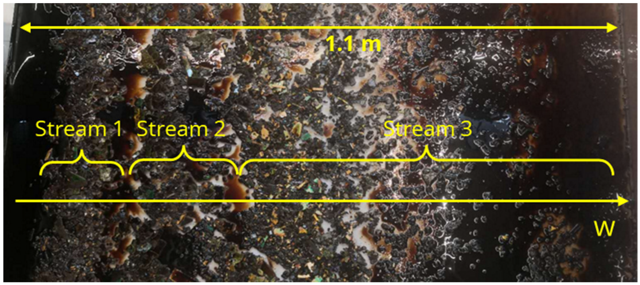
After dropping the feedstock of shredded PCBAs in the fluid, as shown in Figure 4a, the fluid was pumped out, and the top view of deposited particles on the bottom is shown in Figure 5. Along the w axis, the particles were manually divided into three streams. XRF and lead assay analysis were carried out to obtain the mass fractions of gold, silver, and copper in each of the three streams, as well as in the original shredded PCBAs and the feedstock in the MDS. The results are shown in Table 2, where the mass of each particle stream is also listed. Compared with the original shredded PCBAs, the metals in the MDS feedstock were already concentrated a little. After the MDS, the metals in Stream 1 and Stream 2 were concentrated, while Stream 3, with a considerable amount, was a poor stream. This indicates that the metals mainly exist in heavier scraps that were distributed on the left of the container. On the right of the container, the scraps were lighter and visibly less metallic, mainly consisting of resins and plastics. Stream 1 and Stream 2 can be collected as the concentrate product and Stream 3 can be regarded as the tailing. Compared with the MDS feedstock, the mass contents of Au, Ag, and Cu in the concentrate product were increased by 71.3%, 60.6%, and 142.7%, respectively, and the recovery rate was 99.94%, 93.74%, and 100%, correspondingly. This demonstrates that the MDS could be effective in the concentration of Au, Ag, and Cu in the shredded PCBAs. Note that the tailing Stream 3 was 41.7 wt% of the MDS feedstock. Considering that the density of Stream 3 was much smaller than Stream 1 and Stream 2, the bulk volume fraction of Stream 3 was even larger. Therefore, removing Stream 3 by MDS sorting could save much cost to process the material in subsequent metallurgical processes.

3.2. MDS Sorting of Shredded Wires

The role of the new MDS in the recycling of wasted electrical wires was also demonstrated. Traditional recycling of wasted cables focused on copper recovery. However, the plastic fraction is a hazard to the environment, especially when it goes to landfill or incineration. That is why the proper recycling of the plastic fraction is also important [35,36]. Economic recycling of plastics requires techniques to purify the plastic fractions separated from metal fractions. In this experiment, the MDS feedstock, which was the plastic fraction after air table sorting, still contained a small amount of copper, which could be copper wires, non-liberated copper wires covered by plastic hulls, or small copper particles generated during shredding. The impurity of the plastic fraction increases the cost of plastic reproduction and is also a waste of copper.
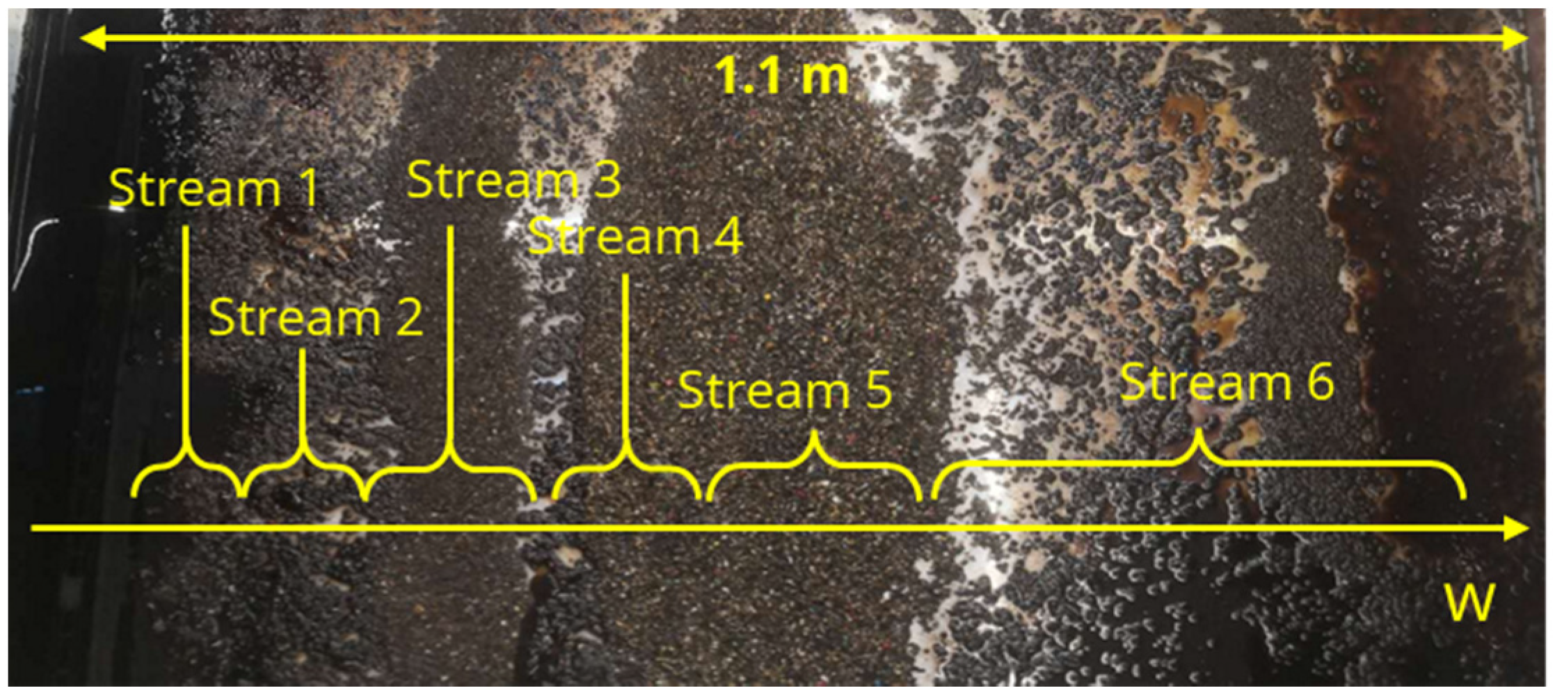
Using the same MDS setup as Figure 4a, the wire scraps deposited on the container bottom, as shown in Figure 6. Note that before the MDS, the float was removed using water. Along the w axis, the particles were manually split into six streams. XRF analysis was carried out for each stream, as well as the feedstock and the float. Copper and aluminum were found to be the main metallic contaminants in the feedstock. Different from copper, which existed in the form of conductive wires, aluminum wires were not observed; thus, it is speculated that aluminum existed as a component of the sheathing material. Table 3 shows the Cu and Al contents in each particle stream and the mass of each particle stream. In Stream 3, 5, 6, and the float, the metallic contaminants were obviously reduced compared with the feedstock. Considering the feedstock was already the separated plastic fraction from the original shredded wires, the MDS could be an advanced alternative to the air table sorting applied by cable recycling industries in the Netherlands. The MDS also has the unique advantage of separating the feedstock into multiple streams with different densities in one single process. In this case, copper was concentrated in Streams 1 and 2, and aluminum was concentrated in Streams 1 and 4. Different streams could go to different downstream processes, depending on the strategy in the industries. Therefore, the MDS is an effective method to purify the plastic fraction, as well as to recover more metals in cable recycling.

3.3. A Pilot Scale Facility of the Innovative MDS

To industrialize the new MDS process, a pilot scale facility was fabricated, as shown in Figure 7, and the design was patented [37]. The separation basin is filled with ferrofluid and is where the MDS happens. The hopper and vibratory feeder are fixed aside from the basin to drop particles in the basin. After dropping, the particles quickly deposit on the bottom in seconds. The inclined permanent magnet, as used in previous sections, is placed underneath the basin. Note that the higher side of the magnet is on the feeder side and the lower side is on the front side of the figure. A mesh belt is continuously moving to transport deposited particles away from the basin. In the basin, the belt lies on the horizontal bottom. The left side of the basin is a slope, where the belt climbs to take the particles out of the fluid. Note that the w axis, which aligns in the width direction of the belt, corresponds to the w axis in Figure 2, Figure 3, Figure 4, Figure 5 and Figure 6. On the collection side of the belt, particles can be collected as several separated streams along the w axis. The above design allows continuous production rather than batch processes as in the experiments; thus, it is applicable in industries.
The facility also has an important fluid recycling system to reduce the consumption of ferrofluid. The purpose is to retrieve the fluid taken out of the basin by the belt and particles and feed it back to the basin. In the washing section, water is sprayed on the belt and the particles on it. The ventilators create a negative air pressure below the belt; thus, the diluted ferrofluid can be sucked through the mesh belt and collected. The diluted fluid will be concentrated again to reach the required magnetization by some methods such as nanofiltration; then, it will be fed back to the separation basin to compensate for the consumption. Although this is not the case in Figure 5, the fluid recycling process is suggested to be continuous and automatic. The same facility is being optimized by TU Delft and the metal recycling company Myne in the Netherlands, and is going to be used at an industrial scale to sort various solid wastes such as cables, incinerator bottom ash, and metal scraps for the concentration and purification of valuable metals and other materials.

4. Conclusions

An innovative MDS process has been developed for granular solid waste sorting which has advantages over the existing industrialized MDS. The process applies an inclined planar magnet, a static magnetic fluid, and a basin with a horizontal bottom and without splitters. The process intrinsically avoids the negative effects of fluid turbulence and particle jamming. A particle sliding phenomenon was identified as a feature of the process, which could help the separation. Experiments demonstrated the effectiveness of the MDS In the sorting of shredded PCBAs to concentrate valuable metals and in the sorting of shredded electrical wires to purify the plastic fractions. A pilot scale facility based on the process has been introduced, where a belt conveying system allows continuous production, and a fluid recycling system reduces the consumption of ferrofluid.

5. Patents

The synthesis method of the ferrofluid used in this work has been patented [26].
The design of the planar magnet used in this work has been patented [25].
The design of the industrial facility based on the innovative MDS process introduced in this work has been patented [37].

Author Contributions

Conceptualization, P.R.; methodology, L.W. and P.R.; software, L.W.; validation, L.W. and P.R.; formal analysis, L.W.; investigation, L.W., M.v.B. and G.T.; resources, P.R. and F.D.M.; data curation, L.W.; writing—original draft preparation, L.W.; writing—review and editing, L.W., F.D.M., M.v.B. and G.T.; visualization, L.W.; supervision, P.R. and F.D.M.; project administration, P.R. and F.D.M.; funding acquisition, P.R. and F.D.M. All authors have read and agreed to the published version of the manuscript.

Funding

This project has received funding from the European Union’s Horizon 2020 research and innovation programme under grant agreement No. 958302. The APC was funded by the TU Delft Library.

Data Availability Statement

Data available on request due to restrictions (e.g., privacy, legal, or ethical reasons).

Acknowledgments

The authors would like to express their deep appreciation to Umincorp and Myne in the Netherlands and TREEE in Italy for providing the materials used in this work.

Conflicts of Interest

The authors declare no conflicts of interest.

References

  1. Sujatha, K.; Radha, R.C. Technologies for segregation and management of solid waste: A review. In Proceedings of the 2016 International Conference on Emerging Trends in Engineering, Technology and Science (ICETETS), Pudukkottai, India, 24–26 February 2016; pp. 1–4. [Google Scholar]
  2. Gundupalli, S.P.; Hait, S.; Thakur, A. A review on automated sorting of source-separated municipal solid waste for recycling. Waste Manag. 2017, 60, 56–74. [Google Scholar] [CrossRef]
  3. Anastassakis, G.N. Solid Waste Separation and Processing: Principles and Equipment. In Handbook of Environmental Engineering; Wiley Online Library: Hoboken, NJ, USA, 2018; pp. 627–671. [Google Scholar]
  4. Lu, W.; Chen, J. Computer vision for solid waste sorting: A critical review of academic research. Waste Manag. 2022, 142, 29–43. [Google Scholar] [CrossRef]
  5. Tanısalı, E.; Özer, M.; Burat, F. Precious metals recovery from waste printed circuit boards by gravity separation and leaching. Miner. Process. Extr. Metall. Rev. 2021, 42, 24–37. [Google Scholar] [CrossRef]
  6. Rem, P.C.; Berkhout, S.P.M. Magnetic Density Separation Device and Method. US10974255B2, 13 April 2021. [Google Scholar]
  7. Papell, S.S. Low Viscosity Magnetic Fluid Obtained by the Colloidal Suspension of Magnetic Particles. US3215572A, 2 November 1965. [Google Scholar]
  8. Scherer, C.; Figueiredo Neto, A.M. Ferrofluids: Properties and applications. Braz. J. Phys. 2005, 35, 718–727. [Google Scholar] [CrossRef]
  9. Rosensweig, R.E. Fluidmagnetic buoyancy. AIAA J. 1966, 4, 1751–1758. [Google Scholar] [CrossRef]
  10. Svoboda, J.; Fujita, T. Recent developments in magnetic methods of material separation. Miner. Eng. 2003, 16, 785–792. [Google Scholar] [CrossRef]
  11. Shimoiizaka, J.; Nakatsuka, K.; Fujita, T.; Kounosu, A. Sink-float separators using permanent magnets and water based magnetic fluid. IEEE Trans. Magn. 1980, 16, 368–371. [Google Scholar] [CrossRef]
  12. Odenbach, S. Ferrofluids-magnetisable liquids and their application in density separation. Magn. Electr. Sep. 1970, 9, 074963. [Google Scholar] [CrossRef]
  13. Mir, L.; Simard, C.; Grana, D. Recovery of nonferrous metals from scrap automobiles by magnetic fluid levitation. In Proceedings of the 3rd Urban Technology Conference and Technical Display, Boston, MA, USA, 25–28 September 1973; p. 959. [Google Scholar]
  14. Muchova, L.; Bakker, E.; Rem, P. Precious metals in municipal solid waste incineration bottom ash. Water Air Soil Pollut. Focus 2009, 9, 107–116. [Google Scholar] [CrossRef]
  15. Khalafalla, S.E.; Reimers, G.W. Separating nonferrous metals in incinerator residue using magnetic fluids. Sep. Sci. 1973, 8, 161–178. [Google Scholar] [CrossRef]
  16. Hu, B.; Giacometti, L.; Di Maio, F.; Rem, P.C. Recycling of WEEE by magnetic density separation. In Proceedings of the Sixth International Conference on Waste Management and Technology, Suzhou, China, 30 August–1 September 2011. [Google Scholar]
  17. Serranti, S.; Luciani, V.; Bonifazi, G.; Hu, B.; Rem, P.C. An innovative recycling process to obtain pure polyethylene and polypropylene from household waste. Waste Manag. 2015, 35, 12–20. [Google Scholar] [CrossRef]
  18. Hu, B. Magnetic Density Separation of Polyolefin Wastes. Ph.D. Thesis, Delft University of Technology, Delft, The Netherlands, 2014. [Google Scholar]
  19. Fujita, T.; Mori, S.; Mamiya, M.; Shimoiizaka, J. An improved sink-float testing apparatus for coal preparation using water based magnetic fluid. In Proceedings of the 11th International Coal Preparation Congress, Tokyo, Japan, 22–25 October 1990; pp. 109–114. [Google Scholar]
  20. Murariu, V.; Svoboda, J.; Sergeant, P. The modelling of the separation process in a ferrohydrostatic separator. Miner. Eng. 2005, 18, 449–457. [Google Scholar] [CrossRef]
  21. Weijmans, F.; Bakker, E.; Rem, P. Magnetic density separation of diamonds from gangue. Environ. Eng. Manag. J. 2009, 8, 981. [Google Scholar]
  22. Svobada, J. Separation in magnetic fluids: Time to meet the technological needs. In Proceedings of the MINPREX 2000 Congress, Melbourne, Australia, 11–13 September 2000. [Google Scholar]
  23. De Koning, J.R.A.; Bakker, E.J.; Rem, P.C. Sorting of vegetable seeds by magnetic density separation in comparison with liquid density separation. Seed Sci. Technol. 2011, 39, 593–603. [Google Scholar] [CrossRef]
  24. Bakker, E.J.; Rem, P.; Berkhout, A.J.; Hartmann, L. Turning magnetic density separation into green business using the cyclic innovation model. Open Waste Manag. J. 2010, 3, 99–116. [Google Scholar] [CrossRef]
  25. Polinder, H.; Rem, P.C. Magnet and Device for Magnetic Density Separation. WO2014158016A1, 5 December 2017. [Google Scholar]
  26. Glazer, P.J.; Paida, S.R.; Rem, P.C. Ferrofluid. US2022/0351887A1, 3 November 2022. [Google Scholar]
  27. Thijs, L.C.; Kuerten, J.G.M.; Zeegers, J.C.H.; Tajfirooz, S. Magnetic density separation of particles in honeycomb-generated wake turbulence. Chem. Eng. Sci. 2023, 278, 118930. [Google Scholar] [CrossRef]
  28. Dellaert, R.A. Turbulence and Particle Behavior in a Magnetic Density Separation Application. Ph.D. Thesis, Eindhoven University of Technology, Eindhoven, The Netherlands, 2021. [Google Scholar]
  29. Houzeaux, G.; Samaniego, C.; Calmet, H.; Aubry, R.; Vázquez, M.; Rem, P. Simulation of magnetic fluid applied to plastic sorting. Open Waste Manag. J. 2010, 3, 127–138. [Google Scholar] [CrossRef]
  30. Kloss, C.; Goniva, C.; Hager, A.; Amberger, S.; Pirker, S. Models, algorithms and validation for opensource DEM and CFD–DEM. Prog. Comput. Fluid Dyn. Int. J. 2012, 12, 140–152. [Google Scholar] [CrossRef]
  31. Phengsaart, T.; Srichonphaisan, P.; Kertbundit, C.; Soonthornwiphat, N.; Sinthugoot, S.; Phumkokrux, N.; Juntarasakul, O.; Maneeintr, K.; Numprasanthai, A.; Park, I. Conventional and recent advances in gravity separation technologies for coal cleaning: A systematic and critical review. Heliyon 2023, 9, e13083. [Google Scholar] [CrossRef]
  32. Falconer, A. Gravity separation: Old technique/new methods. Phys. Sep. Sci. Eng. 2003, 12, 31–48. [Google Scholar] [CrossRef]
  33. Ning, C.; Lin, C.S.K.; Hui, D.C.W.; McKay, G. Waste printed circuit board (PCB) recycling techniques. Chem. Chem. Technol. Waste Valorization 2018, 43, 21–56. [Google Scholar]
  34. Kaya, M. Recovery of metals and nonmetals from electronic waste by physical and chemical recycling processes. Waste Manag. 2016, 57, 64–90. [Google Scholar] [CrossRef]
  35. Díaz, S.; Ortega, Z.; McCourt, M.; Kearns, M.P.; Benítez, A.N. Recycling of polymeric fraction of cable waste by rotational moulding. Waste Manag. 2018, 76, 199–206. [Google Scholar] [CrossRef]
  36. de Araújo, M.C.P.B.; Chaves, A.P.; Espinosa, D.C.R.; Tenório, J.A.S. Electronic scraps–Recovering of valuable materials from parallel wire cables. Waste Manag. 2008, 28, 2177–2182. [Google Scholar] [CrossRef]
  37. Di Maio, F.; Rem, P.C. Method of Separating Scrap Particles, and Particle Separation Assembly (Separation of Materials Heavier than Water). NL2031882, 24 November 2023. [Google Scholar]
Figure 1. Principle of the innovative MDS.
Recycling 09 00048 g001
Figure 2. (a) Experimental setup to demonstrate particle sliding; (b) top view of deposited particles.
Recycling 09 00048 g002
Figure 3. (a) Forces on Particle 2 on the bottom; (b) variation of horizontal forces with w 2 .
Recycling 09 00048 g003
Figure 4. (a) Experimental setup for material sorting; (b) feedstock of shredded PCBAs; (c) feedstock of shredded wires.
Recycling 09 00048 g004
Figure 5. Top view of deposited PCBA scraps.
Recycling 09 00048 g005
Figure 6. Top view of deposited wire scraps.
Recycling 09 00048 g006
Figure 7. Pilot-scale facility of the innovative MDS.
Recycling 09 00048 g007
Table 1. Physical parameters.
ParameterValue
Density of Particle 1, ρ p 1 8500 kg/m3
Density of Particle 2, ρ p 2700 kg/m3
Particle volume, V p 1 cm3
Angle of magnet surface to basin bottom, θ 12°
Fluid density, ρ 1032 kg/m3
Fluid magnetization, M 3368 A/m
Magnetic field strength at magnet surface, B 0 0.63 T
Magnet pole size, p 0.189 m
Table 2. Mass of each particle stream and mass contents of Au, Ag, and Cu in each stream.
Particle StreamMassAu ContentAg ContentCu Content
Original shredded PCBAs9683.9 g18.56 ppm612.73 ppm9.55%
MDS feedstock7479.9 g20.30 ppm682.89 ppm10.24%
Stream 12654.5 g30.07 ppm1369.33 ppm29.57%
Stream 21710.3 g42.05 ppm674.35 ppm17.53%
Stream 33115.4 g0.03 ppm102.63 ppm0.00%
Table 3. Mass of each particle stream and Cu and Al contents in each stream.
Particle StreamMass (g)Cu (wt%)Al (wt%)Cu + Al (wt%)
MDS feedstock488.21.021.132.15
Stream 18.941.881.5843.46
Stream 27.61.380.621.99
Stream 365.10.410.530.94
Stream 4111.00.312.953.25
Stream 5219.00.120.720.84
Stream 622.40.250.290.54
Float54.20.400.110.51
Disclaimer/Publisher’s Note: The statements, opinions and data contained in all publications are solely those of the individual author(s) and contributor(s) and not of MDPI and/or the editor(s). MDPI and/or the editor(s) disclaim responsibility for any injury to people or property resulting from any ideas, methods, instructions or products referred to in the content.