
Impact of Recycled Concrete and Ceramic Fillers on the Performance of Cementitious Systems: Microstructural, Mechanical, and Durability Aspects


Abstract
1. Introduction
2. Materials and Methodology
2.1. Materials
2.1.1. Cement
2.1.2. Fillers
2.1.3. Sand
2.1.4. Water
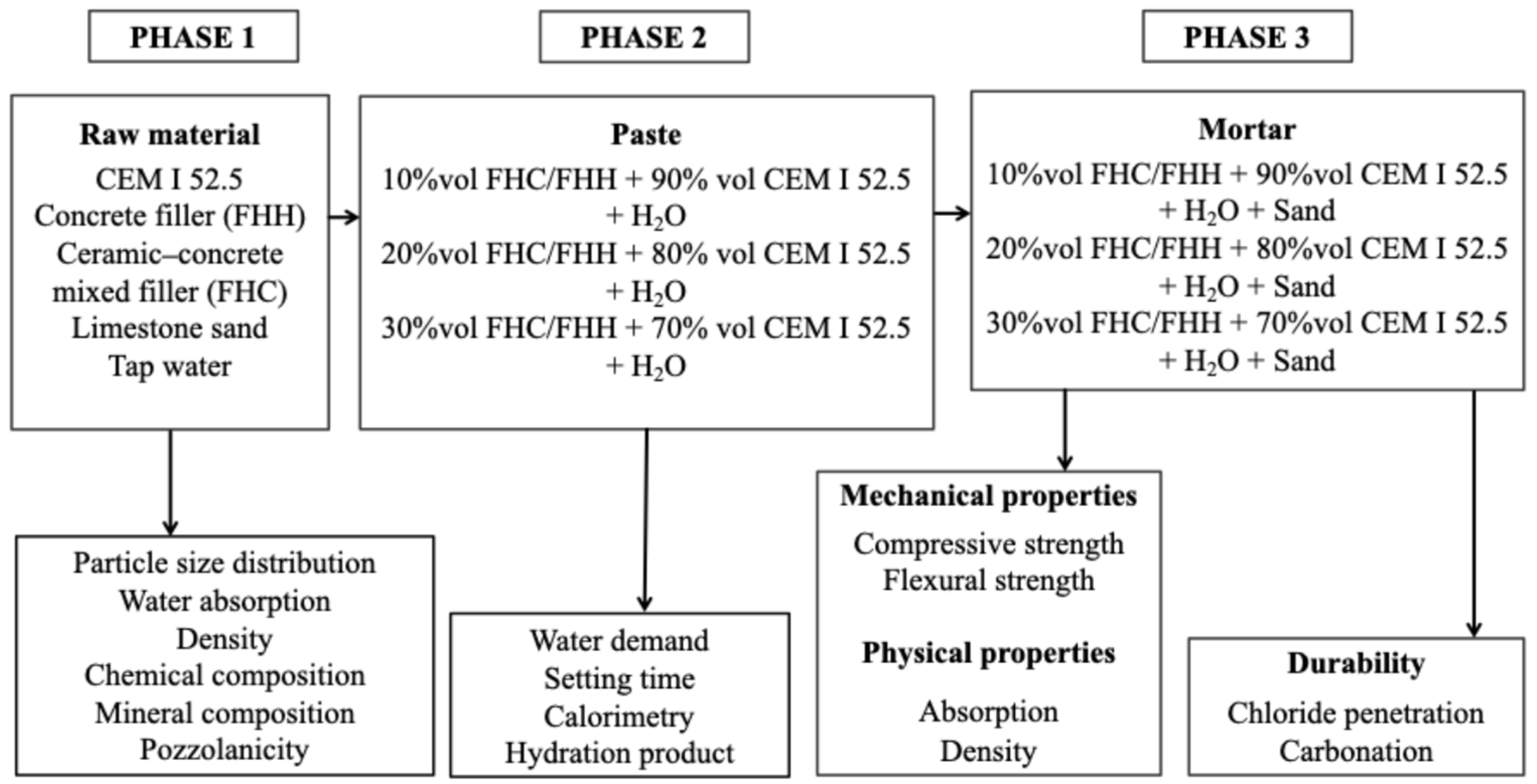
2.2. Materials and Experimental Methodology
3. Results and Discussion
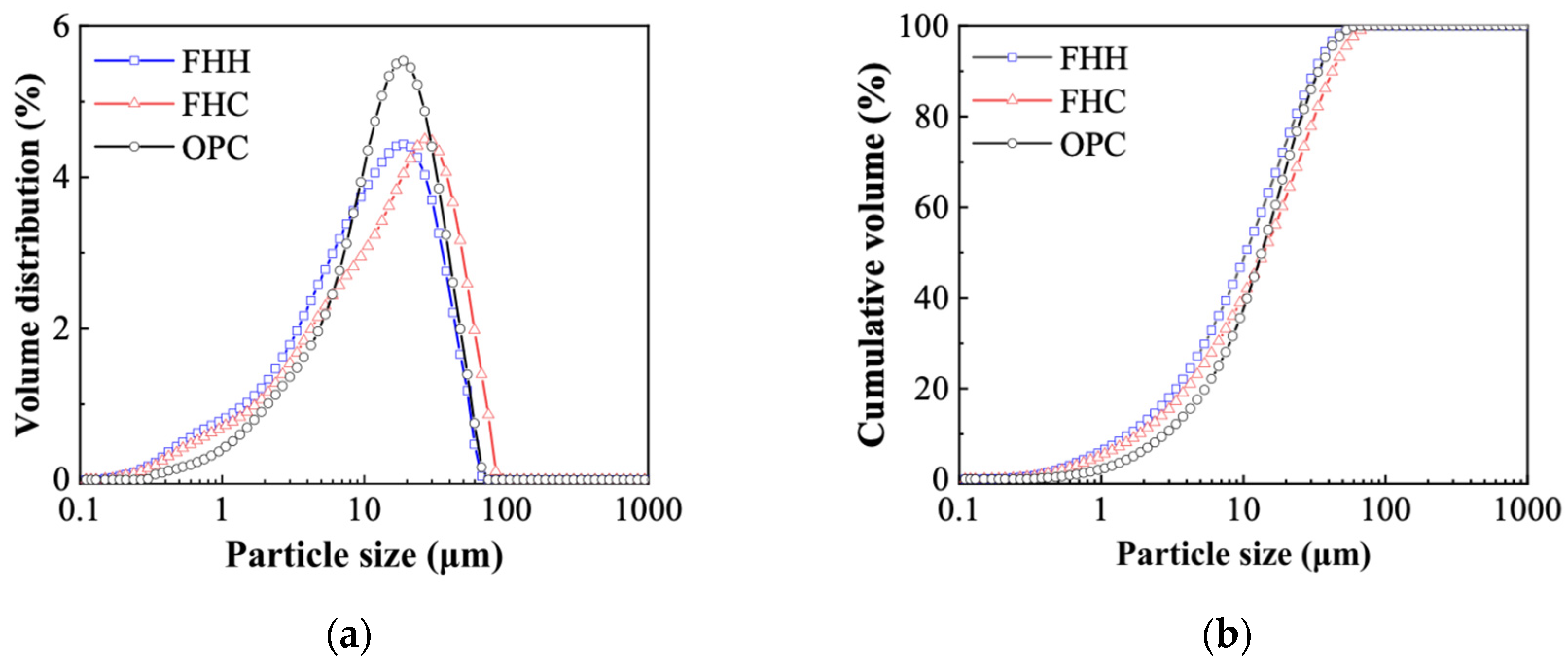
3.1. Raw Material Characterization
3.1.1. XRD
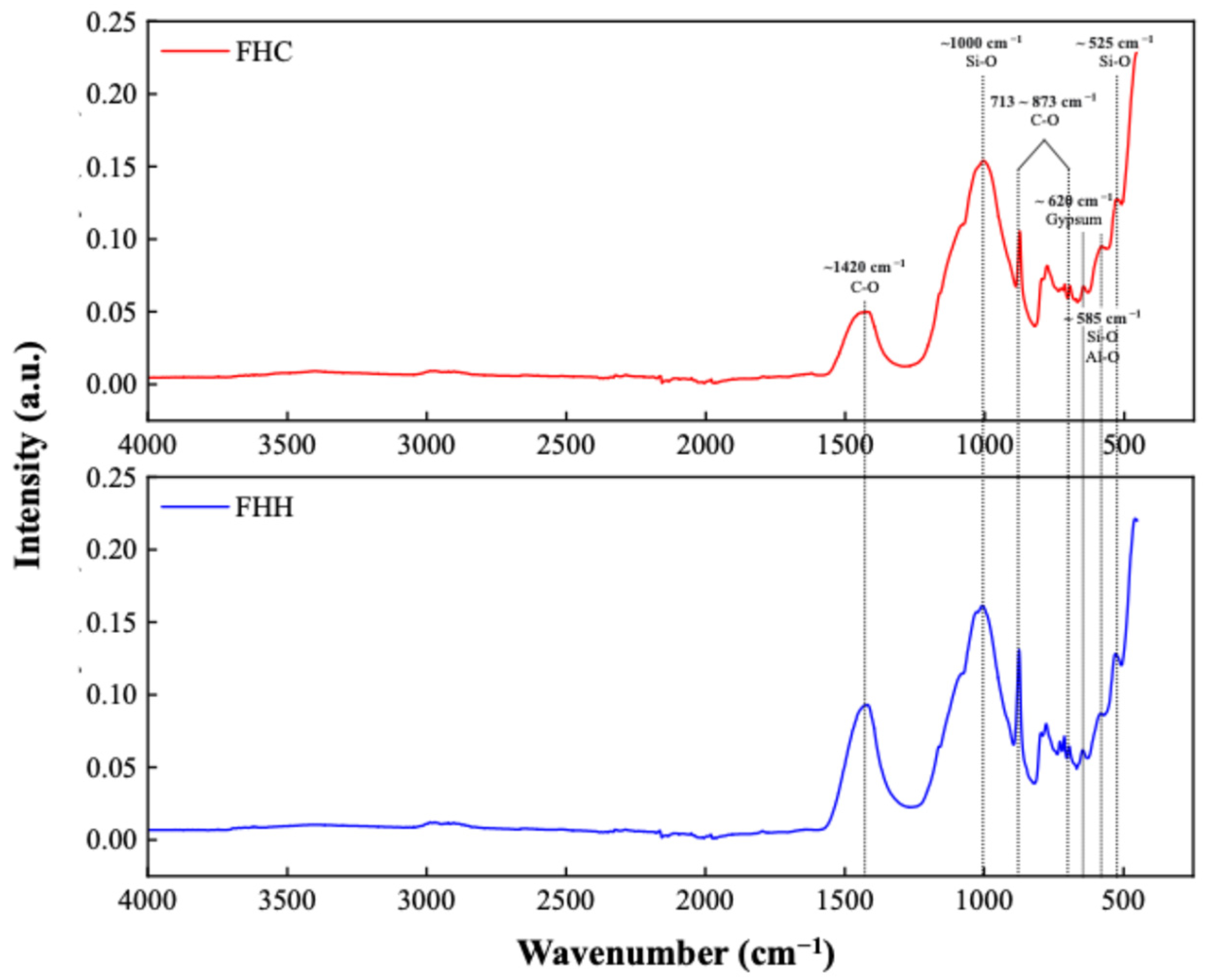
3.1.2. FTIR
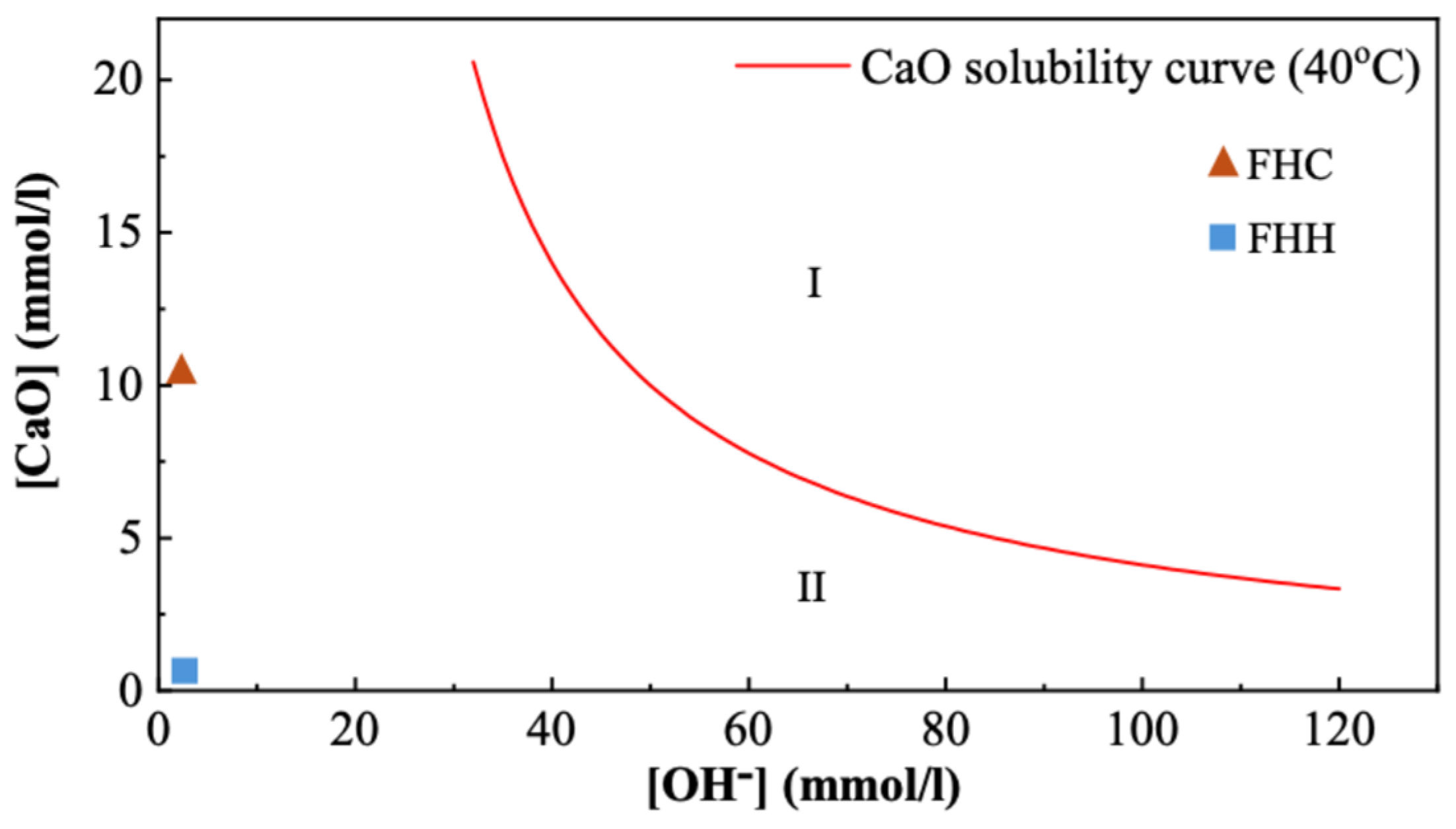
3.1.3. Pozzolanic Activity
3.2. Fresh Properties of FHH/FHC–Cement System
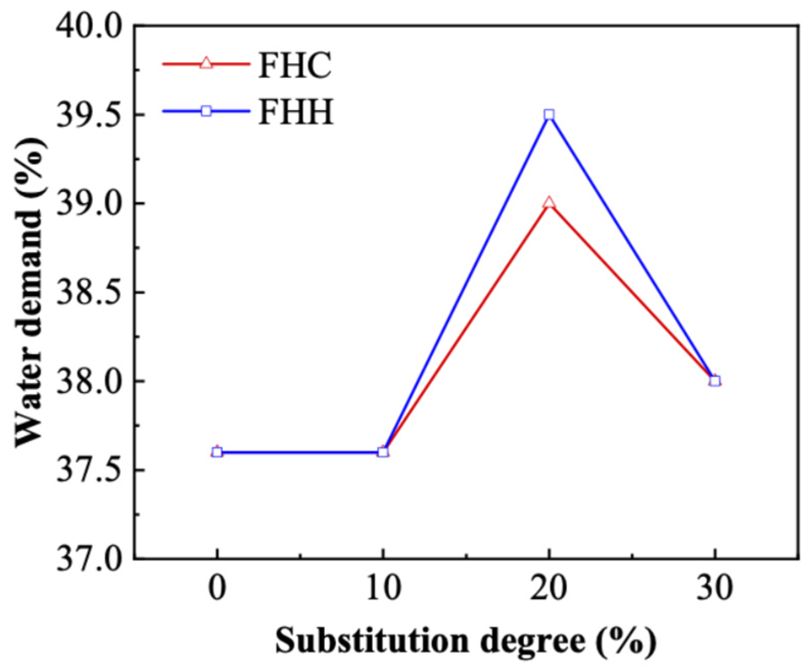
3.2.1. Water Demand
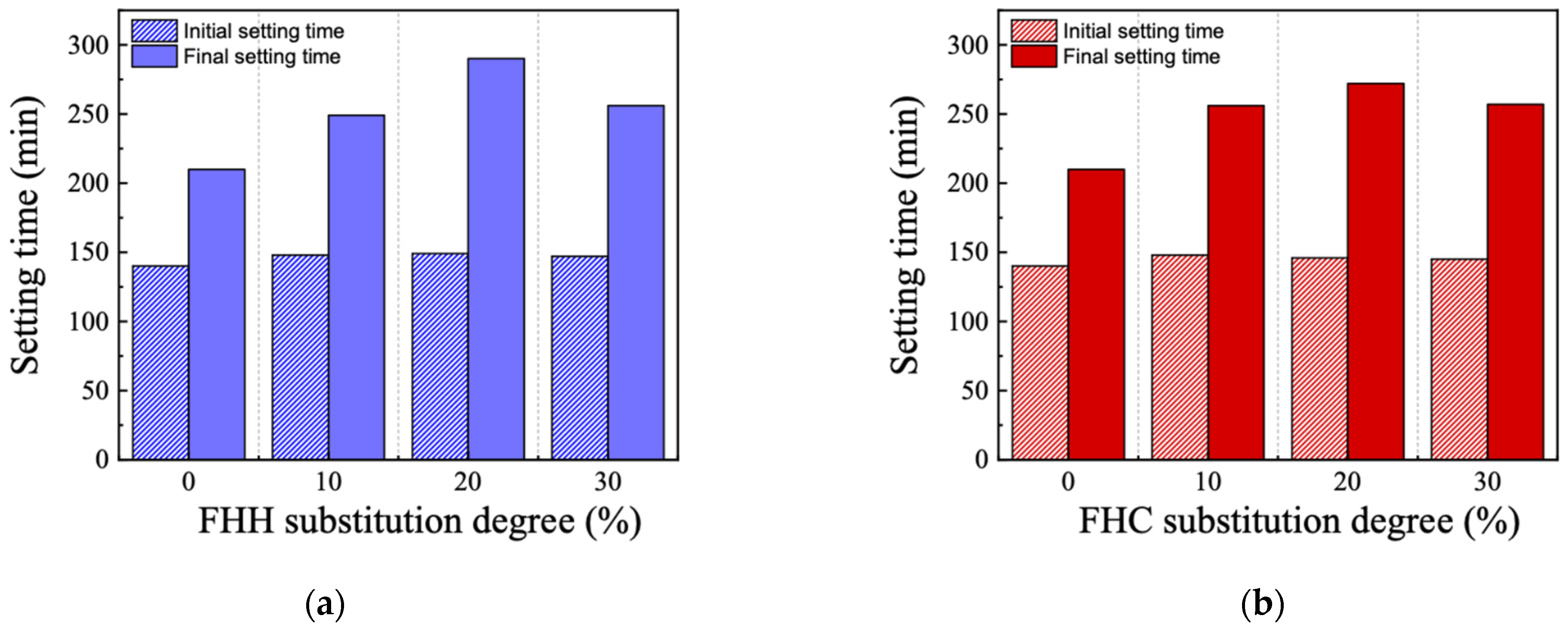
3.2.2. Setting Time
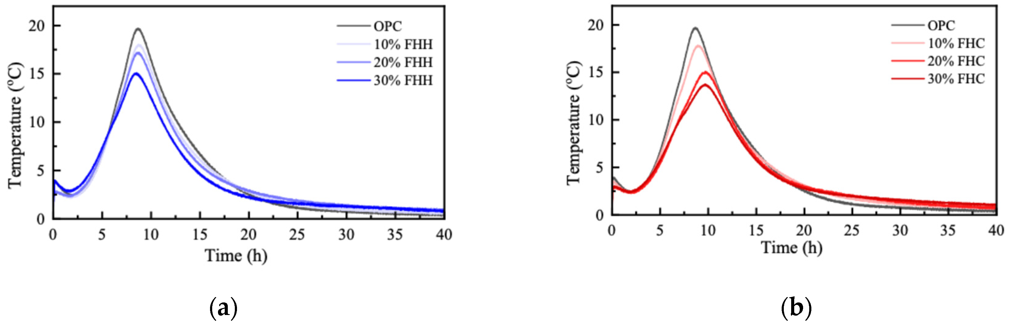
3.2.3. Semi-Adiabatic Calorimetry
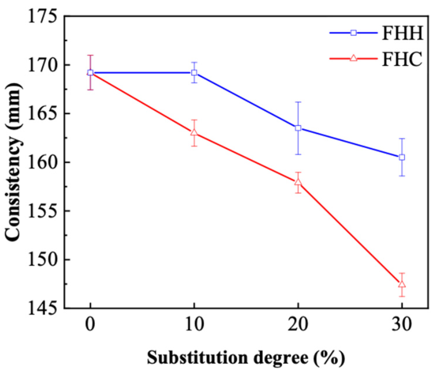
3.2.4. Consistency of FHH/FHC Mortar
3.3. Hardened Properties of FHH/FHC–Cement System
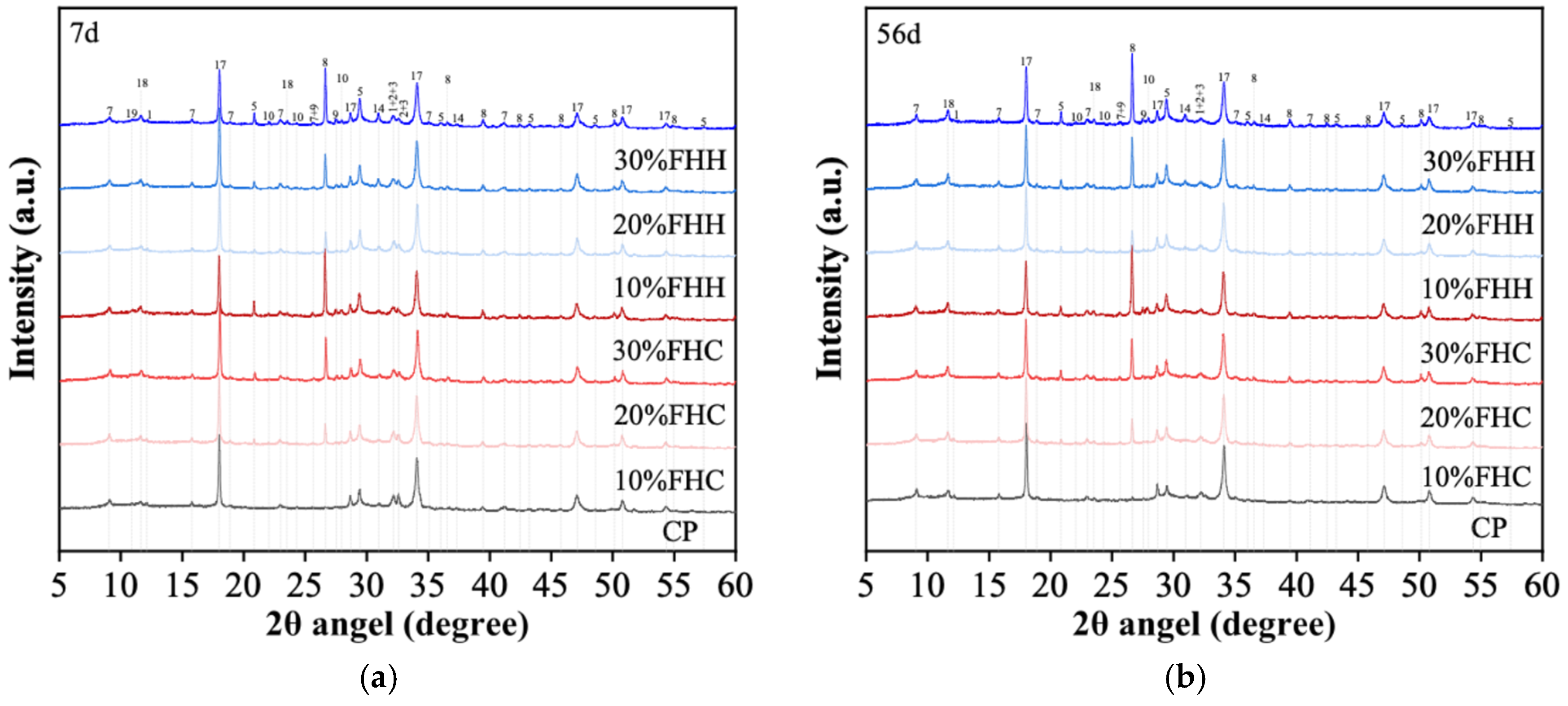
3.3.1. Hydration Products of the Cement Pastes
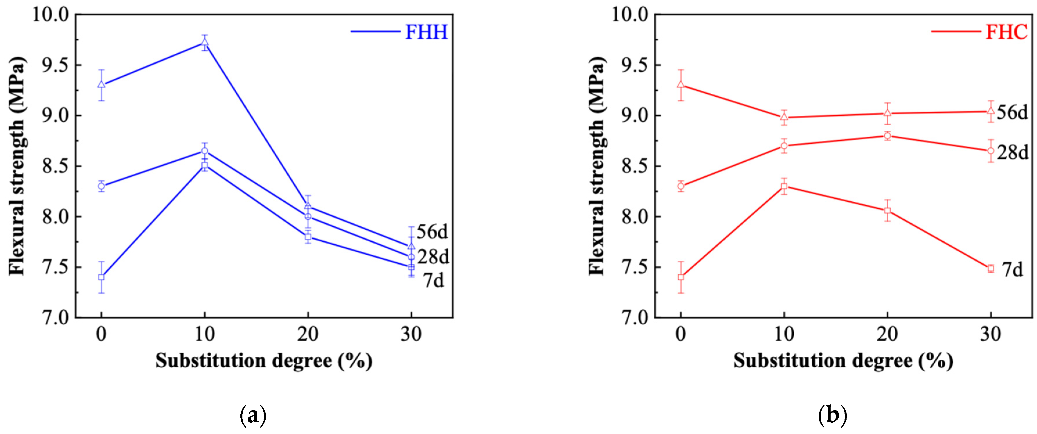
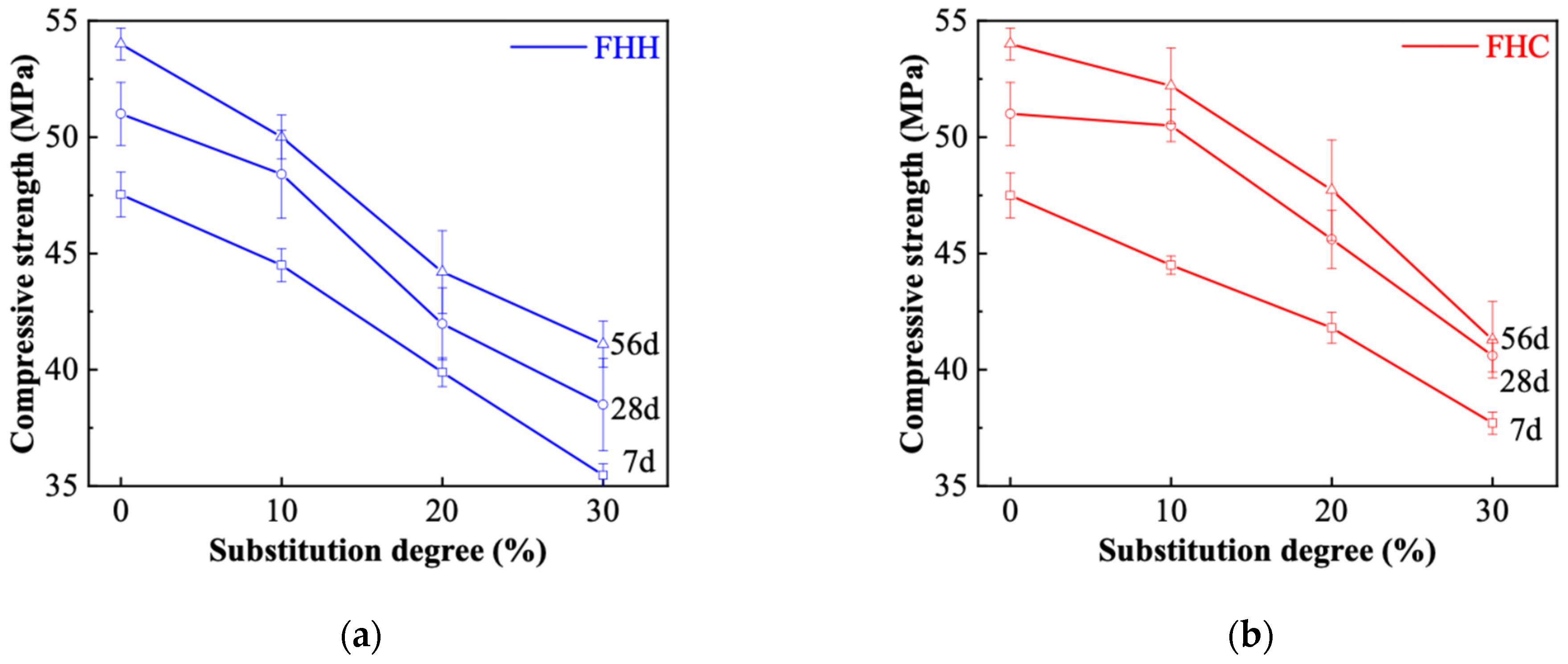
3.3.2. Compressive and Flexural Strength
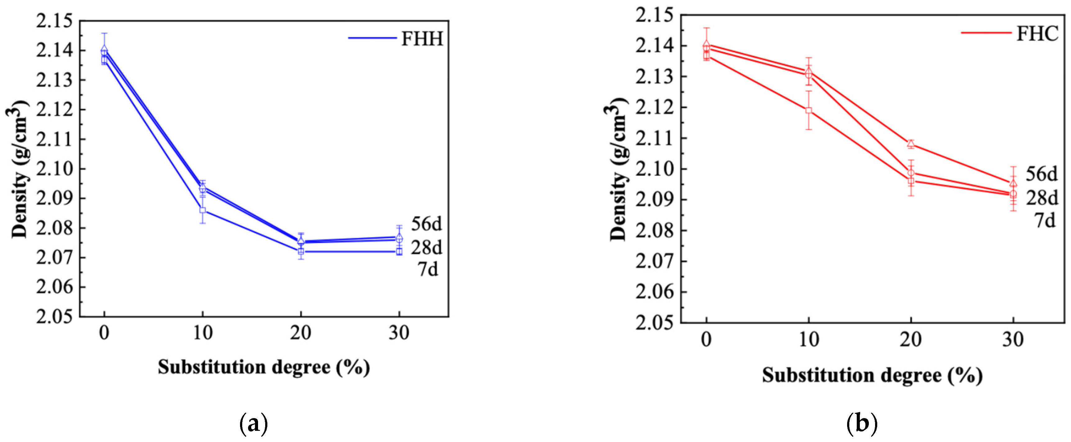
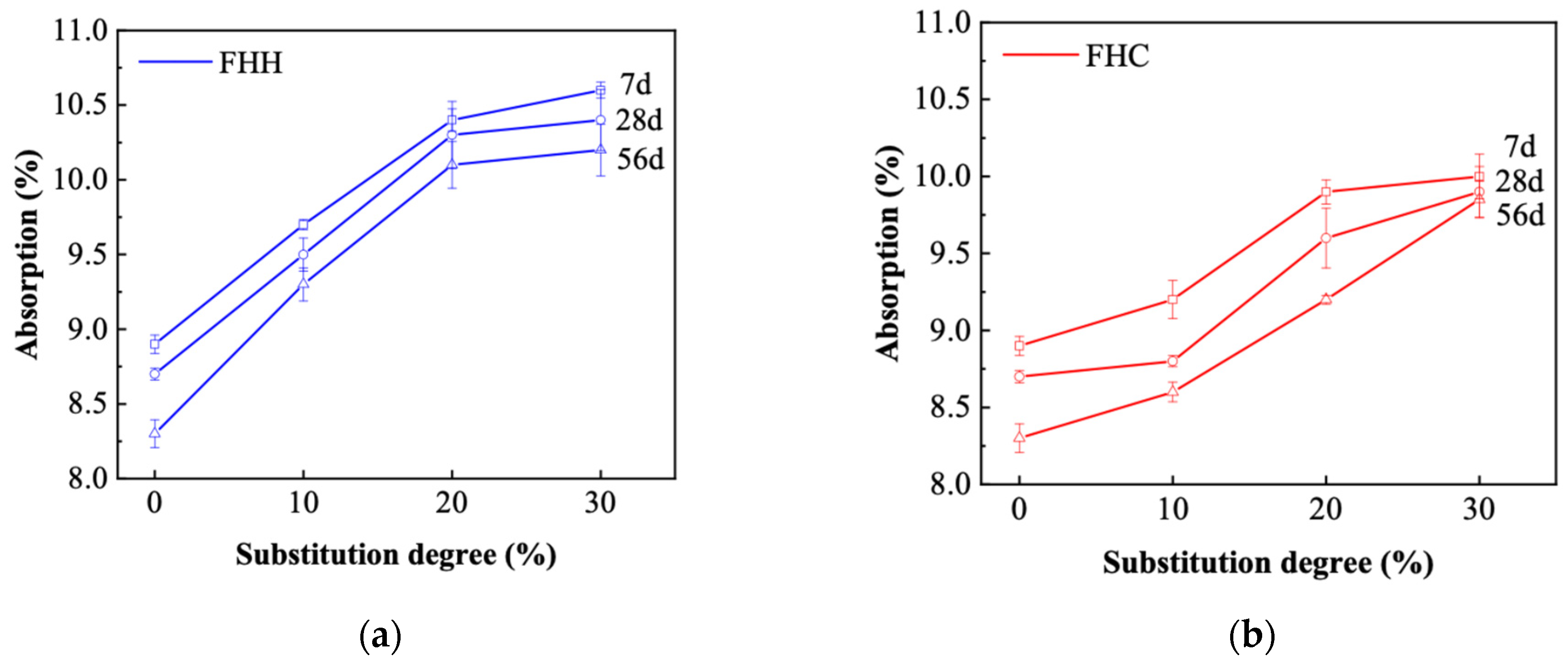
3.3.3. Density and Absorption
3.4. Durability
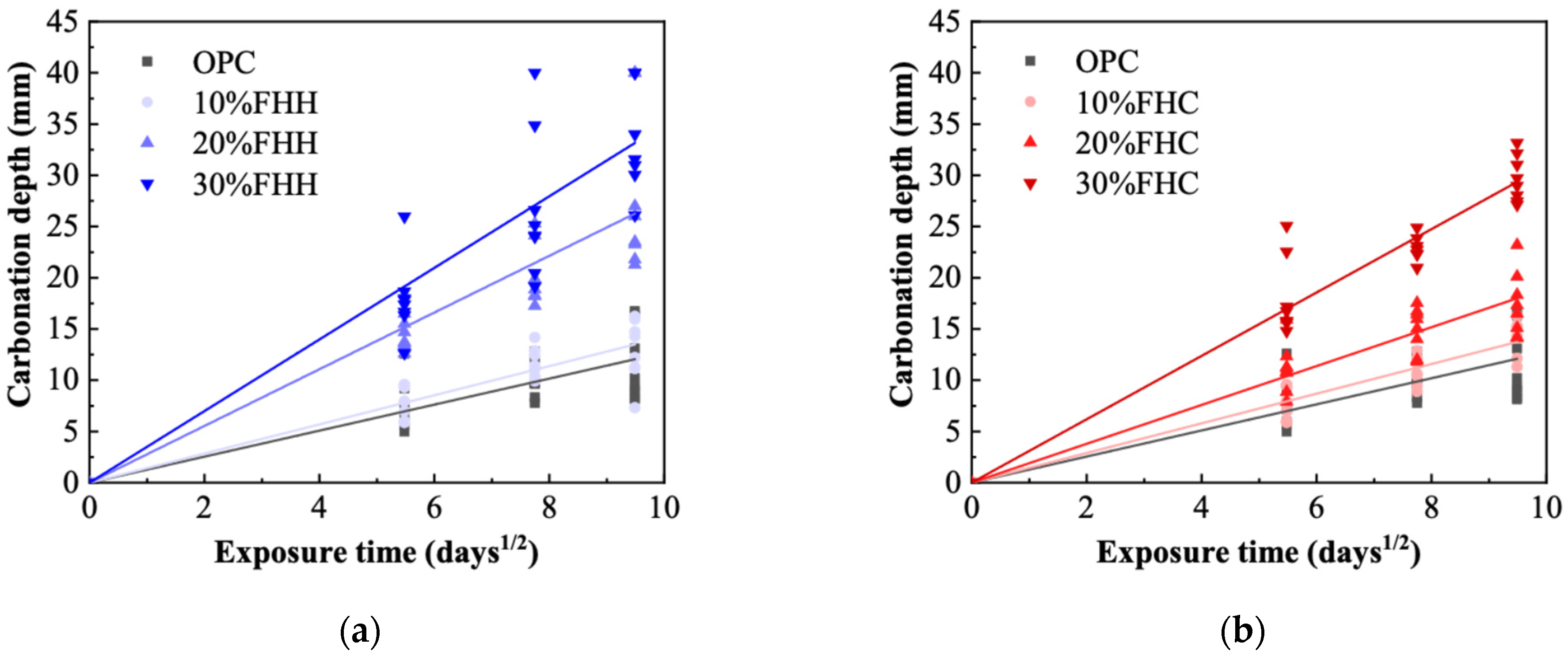
3.4.1. Carbonation
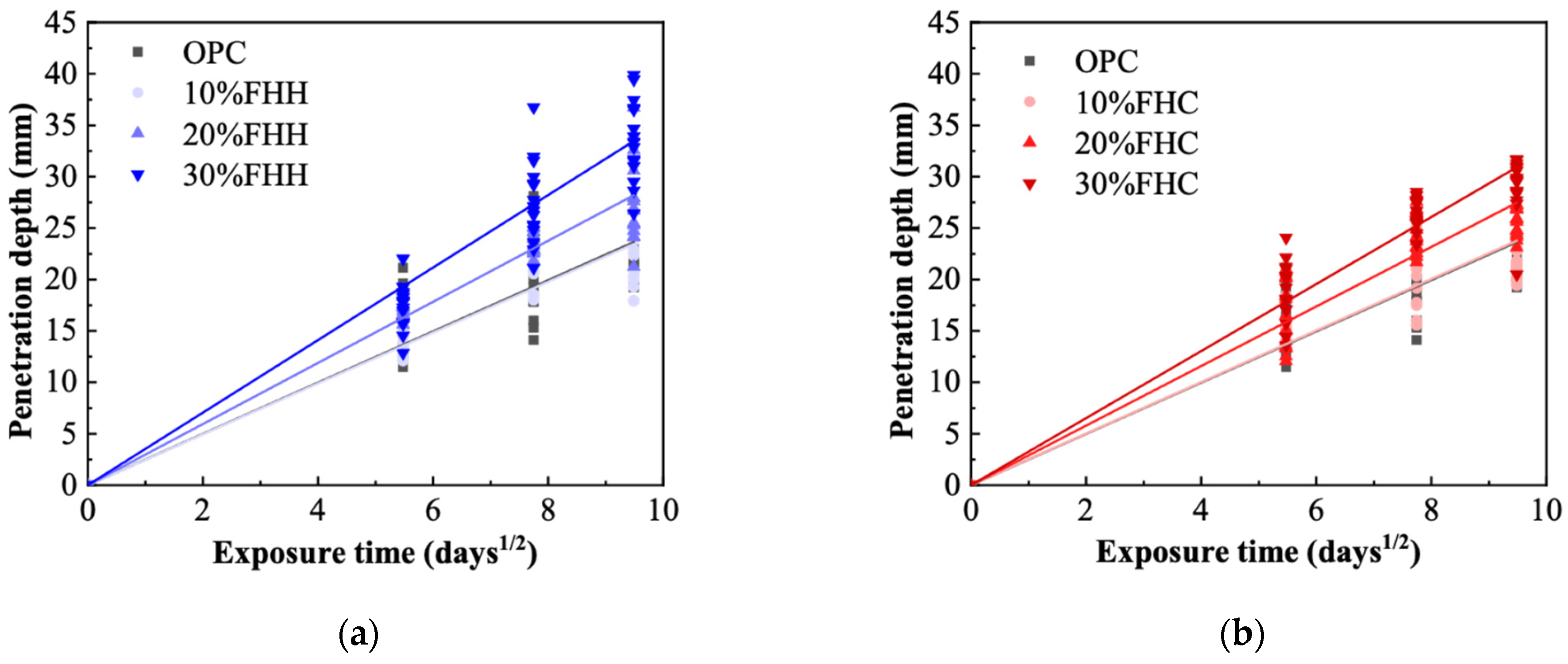
3.4.2. Penetration
4. Conclusions
- FHC enhanced ettringite formation and promoted carboaluminate phases, resulting in improved matrix densification. FHH, with higher calcite and dolomite content, led to more extensive carbonate hydrate formation. These reactions explain the different hydration behaviors observed and their influence on mechanical properties.
- At a 10% replacement level, the compressive strength of FHC–cement systems reached approximately 54 MPa at 56 days, comparable to OPC, indicating suitability for structural use. FHH, while slightly lower in strength, showed higher early-age flexural strength due to its finer particle size and better dispersion, making it appropriate for repair mortars or early-strength applications. However, increasing the replacement ratio exceeded 20% reduced strength in both systems due to clinker dilution and decreased hydration product formation.
- XRD and FTIR analyses confirmed the formation of secondary hydrates and a reduction in portlandite content, particularly in FHH systems. These results indicate that, although FHH exhibits limited chemical reactivity, it contributes to microstructural development through both physical filler effects and partial carbonate-based reactions. In contrast, the microstructural refinement in FHC systems was more pronounced, likely due to its higher alumina and sulfate contents, which facilitated the formation of dense AFm phases. These features translated into improved durability: in both chloride penetration and carbonation tests, the FHC–cement systems with 10% replacement demonstrated significantly lower ingress rates. This suggests strong potential for FHC in aggressive environments, such as marine or chloride-rich conditions.
- These results suggest that FHH and FHC can be effectively used as partial cement replacements at appropriate substitution levels. Their performance depends not only on the replacement level but also on their mineral composition, particle size, and interaction with cement hydration. From an engineering perspective, FHC is viable for partial replacement in structural elements under exposure, while FHH is better suited for non-structural or early-strength applications.
Author Contributions
Funding
Data Availability Statement
Acknowledgments
Conflicts of Interest
Abbreviations
| CDW | Construction and demolition waste |
| FHH | Recycled concrete filler |
| FHC | Recycled ceramic–concrete mixed filler |
| FTIR | Fourier transform infrared spectroscopy |
| XRD | X-ray diffraction |
| XRF | X-ray fluorescence |
| PSD | Particle size distribution |
References
- Gao, T.; Shen, L.; Shen, M.; Liu, L.; Chen, F. Analysis of material flow and consumption in cement production process. J. Clean Prod. 2016, 112, 553–565. [Google Scholar] [CrossRef]
- Kajaste, R.; Hurme, M. Cement industry greenhouse gas emissions—Management options and abatement cost. J. Clean Prod. 2016, 112, 4041–4052. [Google Scholar] [CrossRef]
- Andrew, R.M. Global CO2 emissions from cement production. Earth Syst. Sci. Data 2018, 10, 195–217. [Google Scholar] [CrossRef]
- Desport, L.; Andrade, C.; Corral, D.; Selosse, S. Feasibility, conditions, and opportunities for achieving net-negative emissions in the global cement industry. Int. J. Greenh. Gas Control. 2025, 141, 104280. [Google Scholar] [CrossRef]
- Ding, Z.; Wang, Y.; Zou, P.X.W. An agent based environmental impact assessment of building demolition waste management: Conventional versus green management. J. Clean Prod. 2016, 133, 1136–1153. [Google Scholar] [CrossRef]
- Butera, S.; Christensen, T.H.; Astrup, T.F. Life cycle assessment of construction and demolition waste management. Waste Manag. 2015, 44, 196–205. [Google Scholar] [CrossRef]
- Oliveira, D.R.B.; Leite, G.; Possan, E.; Filho, J.M. Concrete powder waste as a substitution for Portland cement for environment-friendly cement production. Constr. Build. Mater. 2023, 397, 132382. [Google Scholar] [CrossRef]
- Tokareva, A.; Kaassamani, S.; Waldmann, D. Fine demolition wastes as Supplementary cementitious materials for CO2 reduced cement production. Constr. Build Mater. 2023, 392, 131991. [Google Scholar] [CrossRef]
- Li, J.; Deng, X.; Lu, Z.; Li, X.; Hou, L.; Jiang, J.; Yang, F.; Zhang, J.; He, K. Recycled concrete fines as a supplementary cementitious material: Mechanical performances, hydration, and microstructures in cementitious systems. Case Stud. Constr. Mater. 2024, 21, e3575. [Google Scholar] [CrossRef]
- Henríquez, P.A.; Aponte, D.; Ibáñez-Insa, J.; Bizinotto, M.B. Ladle furnace slag as a partial replacement of Portland cement. Constr. Build Mater. 2021, 289, 123106. [Google Scholar] [CrossRef]
- Liu, X.; Li, J.; Bai, C.; Peng, R.; Chi, Y.; Liu, Y. Optimum low-carbon transformation pathways of China’s iron and steel industry towards carbon neutrality based on a dynamic CGE model. Energy 2024, 313, 134023. [Google Scholar] [CrossRef]
- Bhardwaj, N.; Seethamraju, S.; Bandyopadhyay, S. Carbon abatement options for large iron and steel plants in India. J. Clean Prod. 2025, 486, 144505. [Google Scholar] [CrossRef]
- Yan, Y.; Pang, Y.X.; Luo, X.; Lin, Q.; Pang, C.H.; Zhang, H.; Gao, X.; Wu, T. Carbon dioxide-focused greenhouse gas emissions from petrochemical plants and associated industries: Critical overview, recent advances and future prospects of mitigation strategies. Inst. Chem. Eng. 2024, 188, 406–421. [Google Scholar] [CrossRef]
- Snellings, R.; Suraneni, P.; Skibsted, J. Future and emerging supplementary cementitious materials. Cem. Concr. Res. 2023, 171, 107199. [Google Scholar] [CrossRef]
- Juenger, M.C.G.; Snellings, R.; Bernal, S.A. Supplementary cementitious materials: New sources, characterization, and performance insights. Cem. Concr. Res. 2019, 122, 257–273. [Google Scholar] [CrossRef]
- UNE-EN 197-1; Cement—Part 1: Composition, Specifications and Conformity Criteria for Common Cements. AENOR: Madrid, Spain, 2011.
- UNE 80103; Test Methods of Cements. Physical Analysis. Actual Density Determination. AENOR: Madrid, Spain, 2013.
- UNE-EN 196-1; Methods of Testing Cement—Part 1: Determination of Strength. AENOR: Madrid, Spain, 2018.
- UNE-EN 1097-6; Test for Mechanical and Physical Properties of Aggregate—Part 6: Determination of Particle Density and Water Absorption. AENOR: Madrid, Spain, 2014.
- UNE-EN 196-5; Methods of Testing Cement—Part 5: Pozzolanicity Test for Pozzolanic Cement. AENOR: Madrid, Spain, 2011.
- UNE-EN 197-6; Cement—Part 6: Cement with Recycled Building Materials. AENOR: Madrid, Spain, 2023.
- UNE-EN 196-3; Methods of Testing Cement—Part 3: Determination of Setting Times and Soundness. AENOR: Madrid, Spain, 2016.
- Snellings, R.; Chwast, J.; Cizer, Ö.; De Belie, N.; Dhandapani, Y.; Durdzinski, P.; Elsen, J.; Haufe, J.; Hooton, D.; Patapy, C.; et al. RILEM TC-238 SCM recommendation on hydration stoppage by solvent exchange for the study of hydrate assemblages. Mater. Struct. Mater. Constr. 2018, 51, 172. [Google Scholar] [CrossRef]
- UNE-EN 1015-3; Methods of Test for Mortar for Masonry—Part 3: Determination of Consistence of Fresh Mortar (by Flow Table). AENOR: Madrid, Spain, 2000.
- ASTM C642-13; Standard Test Method for Density, Absorption, and Voids in Hardened Concrete. ASTM International: West Conshohocken, PA, USA, 2013.
- UNE-EN 14630; Products and Systems for the Protection and Repair of Concrete Structures, Test methods, Determination of Carbonation Depth in Hardened Concrete by the Phenolphthalein Method. AENOR: Madrid, Spain, 2007.
- NT BUILD 443; Concrete Hardened: Accelerated Chloride Penetration. Nordtest: Espoo, Finland, 1995.
- Ji, J.; Ge, Y.; Balsam, W.; Damuth, J.E.; Chen, J. Rapid identification of dolomite using a Fourier Transform Infrared Spectrophotometer (FTIR): A fast method for identifying Heinrich events in IODP Site U1308. Mar. Geol. 2009, 258, 60–68. [Google Scholar] [CrossRef]
- Jiang, L.; Zheng, H.; Xiong, J.; Fan, Z.; Shen, T.; Xie, H.; Chen, M.; Li, J.; Gu, Z.; Li, H.; et al. Fabrication of negative carbon superhydrophobic self-cleaning concrete coating: High added-value utilization of recycled powders. Cem. Concr. Compos. 2023, 136, 104882. [Google Scholar] [CrossRef]
- Aiqin, W.; Chengzhi, Z.; Ningsheng, Z. The theoretic analysis of the influence of the particle size distribution of cement system on the property of cement. Cem. Concr. Res. 1999, 29, 1721–1726. [Google Scholar] [CrossRef]
- Mehdipour, I.; Khayat, K.H. Effect of particle-size distribution and specific surface area of different binder systems on packing density and flow characteristics of cement paste. Cem. Concr. Compos. 2017, 78, 120–131. [Google Scholar] [CrossRef]
- Zhang, H.; Zhang, C.; He, B.; Yi, S.; Tang, L. Recycling fine powder collected from construction and demolition wastes as partial alternatives to cement: A comprehensive analysis on effects, mechanism, cost and CO2 emission. J. Build. Eng. 2023, 71, 106507. [Google Scholar] [CrossRef]
- Wang, D.; Shi, C.; Farzadnia, N.; Shi, Z.; Jia, H.; Ou, Z. A review on use of limestone powder in cement-based materials: Mechanism, hydration and microstructures. Constr. Build. Mater. 2018, 181, 659–672. [Google Scholar] [CrossRef]
- Scrivener, K.; Ouzia, A.; Juilland, P.; Mohamed, A.K. Advances in understanding cement hydration mechanisms. Cem. Concr. Res. 2019, 124, 105823. [Google Scholar] [CrossRef]
- Da, J.; Neto, S.A.; De La Torre, A.G.; Kirchheim, A.P. Effects of Sulfates on the Hydration of Portland Cement—A Review. Constr. Build. Mater. 2021, 279, 122428. [Google Scholar]
- Klemczak, B.; Gołaszewski, J.; Cygan, G.; Gołaszewska, M.; Jonkers, H.; Zhilyaev, D.; Koenders, E.A. Utilization of waste foam concrete with MPCM as a substitution material for cement in mortars. J. Build. Eng. 2024, 90, 109284. [Google Scholar] [CrossRef]
- de M, T.D.; Nunes, U.S.; Marinho, G.S.; de O, J.C.; Martinelli, A.E.; da Nóbrega, A.C.V. Limestone calcined clay cement (LC3) coating mortars as an energy-efficient option for construction. Constr. Build. Mater. 2024, 437, 136954. [Google Scholar] [CrossRef]
- Caneda-martínez, L.; Monasterio, M.; Moreno-juez, J.; Martínez-ramírez, S.; García, R.; Frías, M. Behaviour and properties of eco-cement pastes elaborated with recycled concrete powder from construction and demolition wastes. Materials 2021, 14, 1299. [Google Scholar] [CrossRef]
- Krishnan, S.; Bishnoi, S. Understanding the hydration of dolomite in cementitious systems with reactive aluminosilicates such as calcined clay. Cem. Concr. Res. 2018, 108, 116–128. [Google Scholar] [CrossRef]
- Çelik, D.N.; Demircan, R.K.; Shi, J.; Kaplan, G.; Durmuş, G. The engineering properties of high strength mortars incorporating juniper seed ash calcined at different temperatures: Comparison with other SCMs. Powder Technol. 2023, 422, 118474. [Google Scholar] [CrossRef]
- Culcu, M.B.; Esen, H. Investigation of mechanical, durability, and thermal properties of sustainable self-compacting mortars containing construction demolition waste and supplementary cementitious materials. J. Build. Eng. 2024, 95, 110361. [Google Scholar] [CrossRef]
- Sabrin, R.; Shahjalal, M.; Bachu, H.A.E.; Habib, M.M.L.; Jerin, T.; Billah, A.M. Recycling of different industrial wastes as supplement of cement for sustainable production of mortar. J. Build. Eng. 2024, 86, 108765. [Google Scholar] [CrossRef]
- Zhang, H.; Li, Q.F.; De Zhou, H.; Song, Z.M. Experimental Study and Prediction Model of the Flexural Strength of concrete Containing Fly Ash and Ground Granulated Blast-Furnace Slag. Adv. Civ. Eng. 2021, 2021, 8773664. [Google Scholar] [CrossRef]
- Bagheri, M.; Lothenbach, B.; Shakoorioskooie, M.; Scrivener, K. Effect of different ions on dissolution rates of silica and feldspars at high pH. Cem. Concr. Res. 2022, 152, 106644. [Google Scholar] [CrossRef]
- Matschei, T.; Lothenbach, B.; Glasser, F.P. The AFm phase in Portland cement. Cem. Concr. Res. 2007, 37, 118–130. [Google Scholar] [CrossRef]
- Tang, J.; Li, Z.; Yu, C.; Yu, J. Viability of using recycled powder from CDW to produce ternary cement type LC3. Case Stud. Constr. Mater. 2024, 21, e3668. [Google Scholar] [CrossRef]
- Li, M.; Zheng, K.; Chen, L.; Prateek, G.; Zhou, X.; Yuan, Q. Using metakaolin to improve properties of aged Portland cement: Effectiveness and the mechanism. Constr. Build. Mater. 2024, 428, 136299. [Google Scholar] [CrossRef]
- Bonavetti, V.L.; Rahhal, V.F.; Irassar, E.F. Studies on the carboaluminate formation in limestone filler-blended cements. Cem. Concr. Res. 2001, 31, 853–859. [Google Scholar] [CrossRef]
- Piasta, W. Analysis of carbonate and sulphate attack on concrete structures. Eng. Fail. Anal. 2017, 79, 606–614. [Google Scholar] [CrossRef]
- Zajac, M.; Skibsted, J.; Durdzinski, P.; Haha, M.B. Effect of alkalis on products of enforced carbonation of cement paste. Constr. Build. Mater. 2021, 291, 123203. [Google Scholar] [CrossRef]
- Ekolu, S.; Solomon, F.; Rakgosi, G. Chloride—Induced delayed ettringite formation in Portland cement mortars. Constr. Build. Mater. 2022, 340, 127654. [Google Scholar] [CrossRef]
- Xu, Q.; Ji, T.; Yang, Z.; Ye, Y. Steel rebar corrosion in artificial reef concrete with sulphoaluminate cement, sea water and marine sand. Constr. Build. Mater. 2019, 227, 116685. [Google Scholar] [CrossRef]


| Material | SiO2 | Al2O3 | Fe2O3 | CaO | MgO | K2O | MnO | SO3 | Others | LOI |
|---|---|---|---|---|---|---|---|---|---|---|
| FHH | 47.93 | 6.25 | 2.31 | 18.52 | 2.82 | 2.06 | 0.04 | 0.5 | 1.22 | 18.35 |
| FHC | 58.13 | 8.96 | 3.2 | 13.04 | 1.1 | 2.53 | 0.05 | 1.17 | 1.68 | 10.14 |
| OPC | 19.96 | 4.68 | 3.32 | 63.27 | 1.52 | 0.81 | 0.03 | 3.11 | 0.67 | 2.63 |
| Substitution Degree (vol.%) | Cement (g) | Filler (g) | Sand (g) | Water (g) | W/B Ratio | |
|---|---|---|---|---|---|---|
| 0% | 450 | 0 | 1350 | 237.5 | 0.528 | |
| FHH | 10% | 405 | 38.2 | 233.9 | ||
| 20% | 360 | 76.4 | 230.3 | |||
| 30% | 315 | 114.6 | 226.7 | |||
| FHC | 10% | 405 | 37.9 | 233.8 | ||
| 20% | 360 | 75.8 | 230 | |||
| 30% | 315 | 113.7 | 226.3 |
| Substitution Degree (vol.%) | Initial Setting Time (min) | Final Setting Time (min) | ||
|---|---|---|---|---|
| FHH | FHC | FHH | FHC | |
| 0% | 140 | 140 | 210 | 210 |
| 10% | 148 | 148 | 249 | 256 |
| 20% | 149 | 146 | 290 | 272 |
| 30% | 147 | 145 | 256 | 257 |
| Substitution Degree (vol.%) | Coefficient of Carbonation (K) | Coefficient of Penetration (D) | ||
|---|---|---|---|---|
| FHH | FHC | FHH | FHC | |
| 0% | 1.27 | 1.27 | 2.49 | 2.49 |
| 10% | 1.42 | 1.49 | 2.47 | 2.51 |
| 20% | 2.77 | 1.90 | 2.97 | 2.90 |
| 30% | 3.49 | 3.09 | 3.53 | 3.26 |
Disclaimer/Publisher’s Note: The statements, opinions and data contained in all publications are solely those of the individual author(s) and contributor(s) and not of MDPI and/or the editor(s). MDPI and/or the editor(s) disclaim responsibility for any injury to people or property resulting from any ideas, methods, instructions or products referred to in the content. |
© 2025 by the authors. Licensee MDPI, Basel, Switzerland. This article is an open access article distributed under the terms and conditions of the Creative Commons Attribution (CC BY) license (https://creativecommons.org/licenses/by/4.0/).
Share and Cite
Han, T.; Aponte, D.; Valls, S.; Bizinotto, M.B. Impact of Recycled Concrete and Ceramic Fillers on the Performance of Cementitious Systems: Microstructural, Mechanical, and Durability Aspects. Recycling 2025, 10, 108. https://doi.org/10.3390/recycling10030108
Han T, Aponte D, Valls S, Bizinotto MB. Impact of Recycled Concrete and Ceramic Fillers on the Performance of Cementitious Systems: Microstructural, Mechanical, and Durability Aspects. Recycling. 2025; 10(3):108. https://doi.org/10.3390/recycling10030108
Chicago/Turabian StyleHan, Tianjun, Diego Aponte, Susana Valls, and Marilda Barra Bizinotto. 2025. "Impact of Recycled Concrete and Ceramic Fillers on the Performance of Cementitious Systems: Microstructural, Mechanical, and Durability Aspects" Recycling 10, no. 3: 108. https://doi.org/10.3390/recycling10030108
APA StyleHan, T., Aponte, D., Valls, S., & Bizinotto, M. B. (2025). Impact of Recycled Concrete and Ceramic Fillers on the Performance of Cementitious Systems: Microstructural, Mechanical, and Durability Aspects. Recycling, 10(3), 108. https://doi.org/10.3390/recycling10030108