


Optimal Capacity Configuration of Wind–Solar Hydrogen Storage Microgrid Based on IDW-PSO

Abstract
:1. Introduction
2. Wind–Solar Hydrogen Microgrid System
2.1. Modeling of Generator Set
2.1.1. Photovoltaic Generation System
2.1.2. Wind Power Generation Model
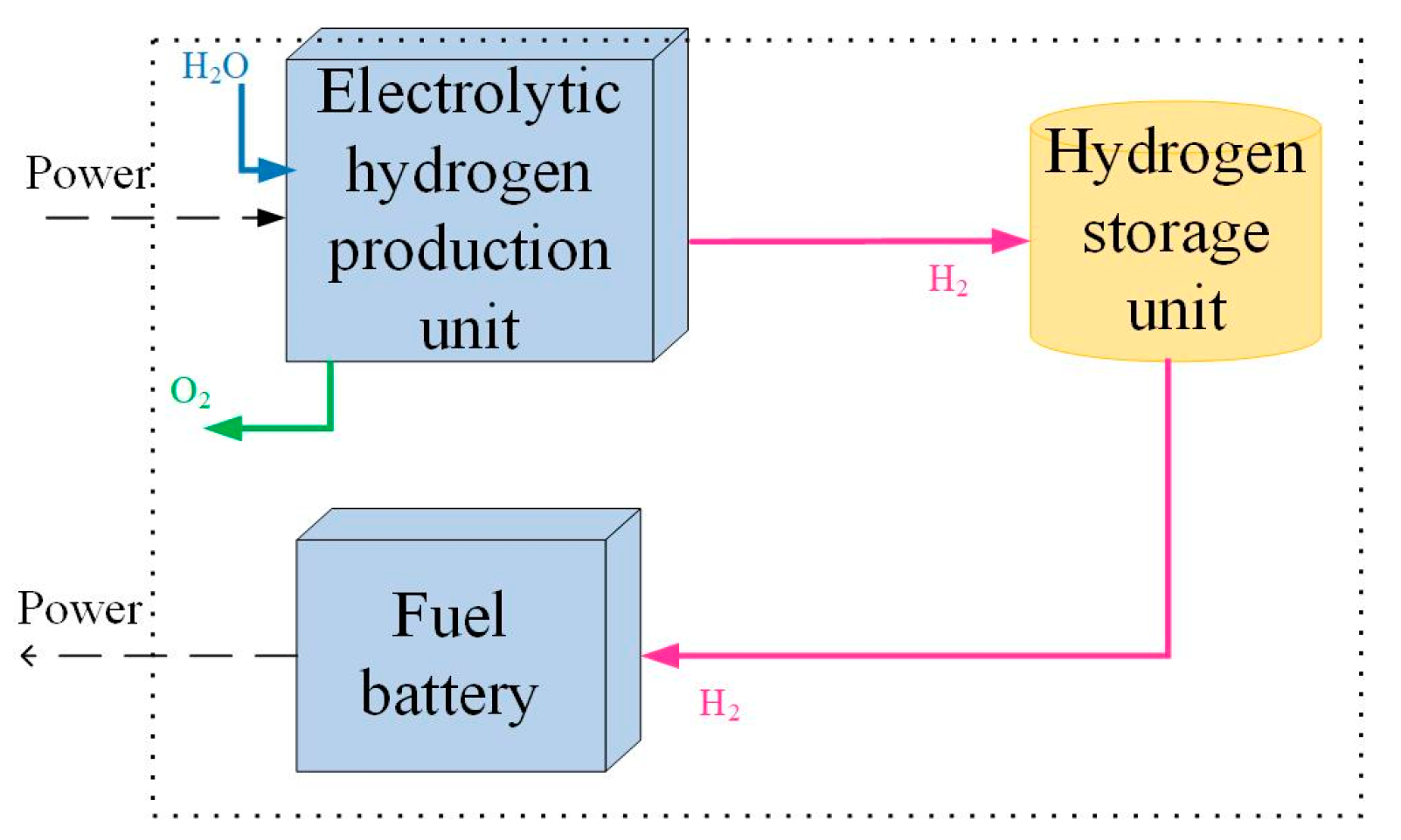
2.2. Modeling of Hydrogen Energy Storage System
2.2.1. Mathematical Modeling of Electrolytic Cell
2.2.2. Mathematical Modeling of Fuel Cell
2.2.3. Mathematical Modeling of Hydrogen Storage Device
2.3. Battery Modeling
3. Capacity Optimal Allocation Model
3.1. Objective Function
3.2. Constraints
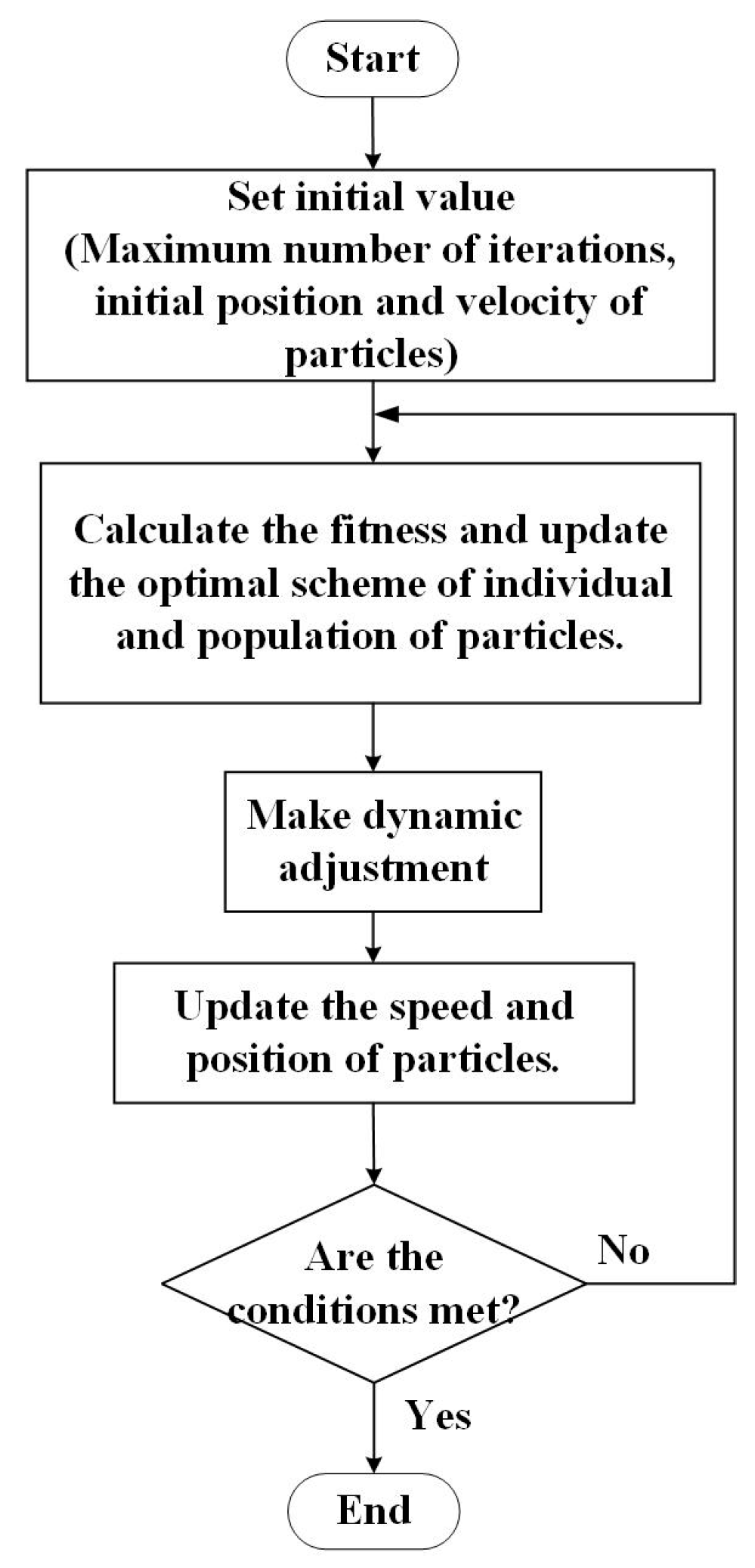
4. Improved Particle Swarm Optimization Algorithm
4.1. Particle Swarm Optimization
4.2. Improved Particle Swarm Optimization
4.3. Solution Steps
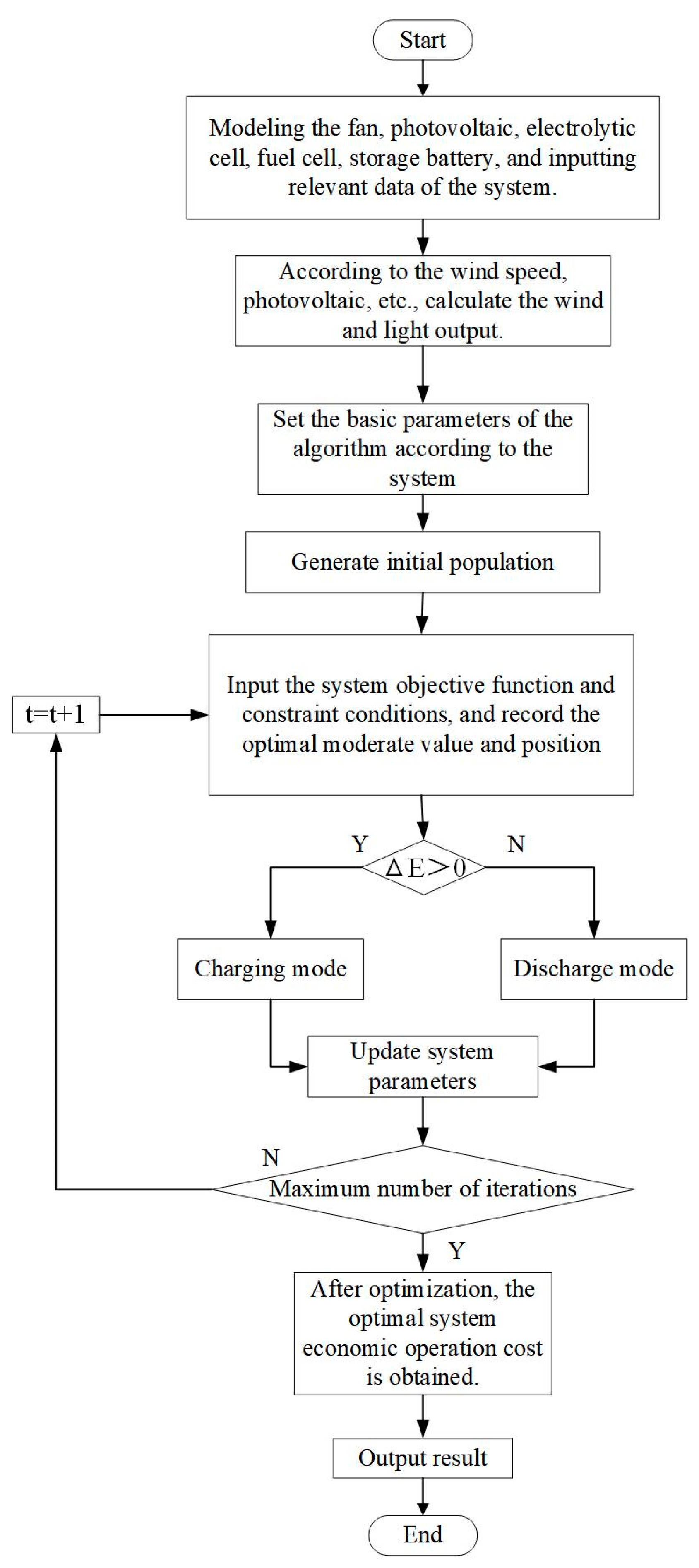
5. Model Solving
- Step (1):
- Modeling each unit of the microgrid, inputting data such as wind speed and load, and inputting relevant parameters;
- Step (2):
- Initialize the calculated output of photovoltaic and wind power generation;
- Step (3):
- Input system constraints and objective functions;
- Step (4):
- Calculate whether the wind and solar power generation meet the load demand ΔE, execute an objective function, and select different operation processes;
- Step (5):
- After executing the objective function, check whether the microgrid is within the constraint range and update the relevant parameters of the system;
- Step (6):
- Whether the maximum number of iterations has been reached. Without satisfying the condition, the program will continue to run;
- Step (7):
- Obtain optimal economic operating cost and related data.
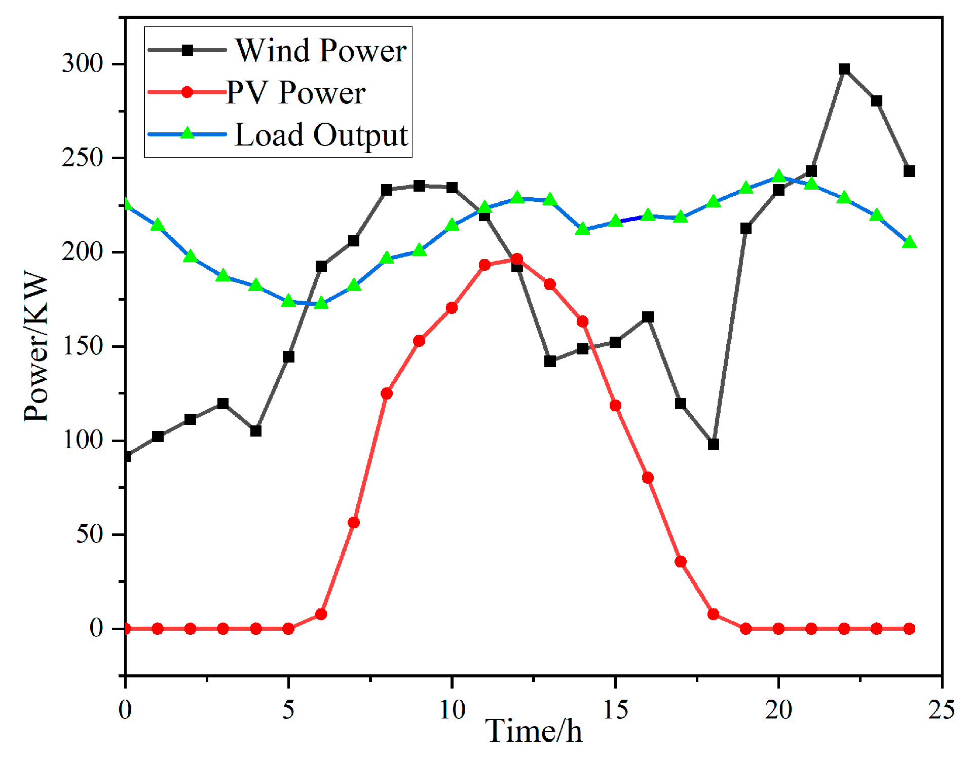
6. Example Analysis
Simulation Results Analysis
7. Conclusions
Author Contributions
Funding
Institutional Review Board Statement
Informed Consent Statement
Data Availability Statement
Conflicts of Interest
References
- Xia, D. Overview of new energy power system stability. Sci. Technol. Innov. Appl. 2021, 331, 69–72. [Google Scholar]
- Lian, Z. Research on Capacity Allocation Optimization of Hybrid Energy Storage System of Wind Power Heat Pump Based on Particle Swarm Optimization. Master’s Thesis, Shenyang University of Technology, Shenyang, China, 2021. [Google Scholar]
- Xiong, Y.; Chen, L.; Zheng, T.; Si, Y.; Mei, S. Optimal configuration of hydrogen energy storage in low-carbon park integrated energy system considering electricity-heat-gas coupling characteristics. Electr. Power Autom. Equip. 2021, 41, 31–38. [Google Scholar]
- Lei, S.; He, Y.; Zhang, J.; Deng, K. Optimal Configuration of Hybrid Energy Storage Capacity in a Microgrid Based on Variational Mode Decomposition. Energies 2023, 16, 4307. [Google Scholar] [CrossRef]
- Li, W.; Jin, R.; Ma, X.; Zhang, G. Capacity Optimal Allocation Method and Frequency Division Energy Management for Hybrid Energy Storage System Considering Grid-Connected Requirements in Photovoltaic System. Energies 2023, 16, 4154. [Google Scholar] [CrossRef]
- Xie, H.; Zheng, S.; Ni, M. Microgrid Development in China: A method for renewable energy and energy storage capacity configuration in a megawatt-level isolated microgrid. IEEE Electrif. Mag. 2017, 5, 28–35. [Google Scholar] [CrossRef]
- Xiu, X. Research on Optimal Allocation of Energy Storage System Capacity and Life Cycle Economic Evaluation Method. Master’s Thesis, China Agricultural University, Beijing, China, 2018. [Google Scholar]
- Sun, H.; Jie, C.; Liang, S.; Hu, J.; Zang, J.; Li, Y. Optimization of double-layer energy storage capacity of wind, solar and electricity grid-connected based on improved slime mold algorithm. Power Grid Clean Energy 2023, 39, 128–136. [Google Scholar]
- Sun, S. Study on Optimal Allocation and Economic Operation Model of Multi-Energy Microgrid. Master’s Thesis, Hefei University of Technology, Hefei, China, 2012. [Google Scholar]
- Ye, C.; Huang, M.; Wang, Y.; Sun, F.; Zhong, Y. Optimal configuration of wind-solar hybrid power supply system based on discrete probability model. Power Syst. Autom. 2013, 37, 48–54. [Google Scholar]
- Zhou, J.L.; Wu, Y.N.; Zhong, Z.M. Modeling and configuration optimization of the natural gas-wind-photovoltaic-hydrogen integrated energy system: A novel deviation satisfaction strategy. Energy Convers. Manag. 2021, 243, 114340. [Google Scholar] [CrossRef]
- Xu, C.; Liu, J. Application value, challenge and prospect of hydrogen energy storage in China’s new power system. China Eng. Sci. 2022, 24, 89–99. [Google Scholar] [CrossRef]
- Zhang, J.; Cheng, H.; Hu, Z.; Ma, Z.; Zhang, J.; Yao, L. Power System Probabilistic Production Simulation Including Wind Farms. Proc. CSEE 2009, 29, 34–39. [Google Scholar]
- Yu, X. Study on Optimal Allocation and Operation of Comprehensive Energy System in the Park with Hydrogen Storage and Heat Storage. Master’s Thesis, North China Electric Power University, Beijing, China, 2020. [Google Scholar]
- Hong, F.; Xu, F.; Liu, G. Optimal capacity allocation of photovoltaic hydrogen storage system considering load demand response. Power Supply 2023, 40, 45–51. [Google Scholar] [CrossRef]
- Zhao, B.; Zhao, P.; Hu, J.; Niu, M.; Xiao, Y.; Liu, F. Overview of Hydrogen Energy Storage Technology in Large Scale Intermittent Renewable Energy Integration Application. Dianqi Yu Nengxiao Guanli Jishu 2018, 16, 1–7. [Google Scholar]
- Peng, S.; Zhu, L.; Dou, Z.; Liu, D.; Yang, R.; Pecht, M. Method of Site Selection and Capacity Setting for Battery Energy Storage System in Distribution Networks with Renewable Energy Sources. Energies 2023, 16, 3899. [Google Scholar] [CrossRef]
- Liu, H.; Wang, S.; Liu, G.; Zhang, J.; Wen, S. SARAP Algorithm of Multi-Objective Optimal Capacity Configuration for WT-PV-DE-BES Stand-Alone Microgrid. IEEE Access 2020, 8, 126825–126838. [Google Scholar] [CrossRef]
- Zhu, Z.; Guo, J.; Yu, G.; Xu, M.; Hu, Z. Bi-Layer Optimization Model for Energy Storage Systems Under Wind and PV Access. Acta Energiae Solaris Sin. 2022, 43, 443–451. [Google Scholar]
- Du, G.; Zhao, D.; Liu, X. Research review on optimal scheduling considering wind power uncertainty. Proc. CSEE 2022, 10, 1–21. [Google Scholar]
- Xie, X.; Wang, H.; Tian, S.; Liu, Y. Optimal capacity configuration of hybrid energy storage for an isolated microgrid based on QPSO algorithm. In Proceedings of the International Conference on Electric Utility Deregulation & Restructuring & Power Technologies, Changsha, China, 26–29 November 2015. [Google Scholar] [CrossRef]
- Li, Q.; Zhao, S.; Pu, Y.; Chen, W.; Yu, J. Capacity Optimization of Hybrid Energy Storage Microgrid Considering Electricity-Hydrogen Coupling. Trans. China Electrotech. Soc. 2021, 36, 486–495. [Google Scholar]
- Wang, C.; Meng, J.; Wang, Y.; Li, C. Multi-source Coordinated Control Strategy Considering Battery’s SOC for Islanded DC Microgrid. High Volt. Eng. 2018, 44, 160–168. [Google Scholar]
- Pan, X.; Liu, K.; Wang, J.; Hu, Y.; Zhao, J. Capacity Allocation Method Based on Historical Data-Driven Search Algorithm for Integrated PV and Energy Storage Charging Station. Sustainability 2023, 15, 5480. [Google Scholar] [CrossRef]
- Xu, L.; Ruan, X.; Zhang, B.; Mao, C. Improved optimal allocation method of wind-solar hybrid power generation system capacity. J. China Electr. Eng. 2012, 32, 11. [Google Scholar]
- Dang, X.; He, B.; Sun, J.; Kong, L.; Meng, F. Photovoltaic maximum power point tracking based on improved particle swarm optimization. Shandong Electr. Power Technol. 2022, 49, 36–43. [Google Scholar]
- Shi, Y.H.; Eberhart, R.C. Empirical study of particle swarm optimization. In Proceedings of the Congress on Evolutionary Computation, Washington, DC, USA, 6–9 July 1999. [Google Scholar] [CrossRef]
- Dong, H.; Li, D.; Zhang, X. A Particle Swarm Optimization Algorithm with Dynamic Adjustment of Inertia Weight. Comput. Sci. 2018, 45, 98–102+139. [Google Scholar]
- Mao, K.F.; Bao, G.Q.; Xu, C. Particle Swarm Optimization Algorithm Based on Non-symmetric Learning Factor Adjusting. Comput. Eng. 2010, 36, 182–184. [Google Scholar]
- Li, Y.; Guo, X.; Dong, H.; Gao, Z. Optimal Capacity Configuration of Wind/PV/Storage Hybrid EnergyStorage System in Microgrid. Power Syst. Its Acta Autom. Sin. 2020, 32, 6. [Google Scholar] [CrossRef]
- Kennedy, J.; Eberhart, R.C. A discrete binary version of the particle swarm algorithm. In Proceedings of the 1997 IEEE International Conference on Systems, Man, and Cybernetics. Computational Cybernetics and Simulation, Orlando, FL, USA, 12–15 October 1997. [Google Scholar] [CrossRef]


| Parameter | Value |
|---|---|
| The daily investment cost of storage battery is RMB/set | 397 |
| Battery charging efficiency/% | 0.75 |
| Battery discharge efficiency/% | 0.85 |
| The daily investment cost of hydrogen energy storage is RMB/set | 534 |
| Hydrogen storage charging efficiency/% | 0.75 |
| Hydrogen energy storage discharge efficiency/% | 0.6 |
| Efficiency of inverter/% | 0.95 |
| Type | Service life/year |
| Wind generator [30] | 20 |
| PV | 25 |
| Storage battery | 15 |
| Electrolytic bath | 15 |
| Hydrogen storage tank | 25 |
| Fuel battery | 10 |
| Inverter | 20 |
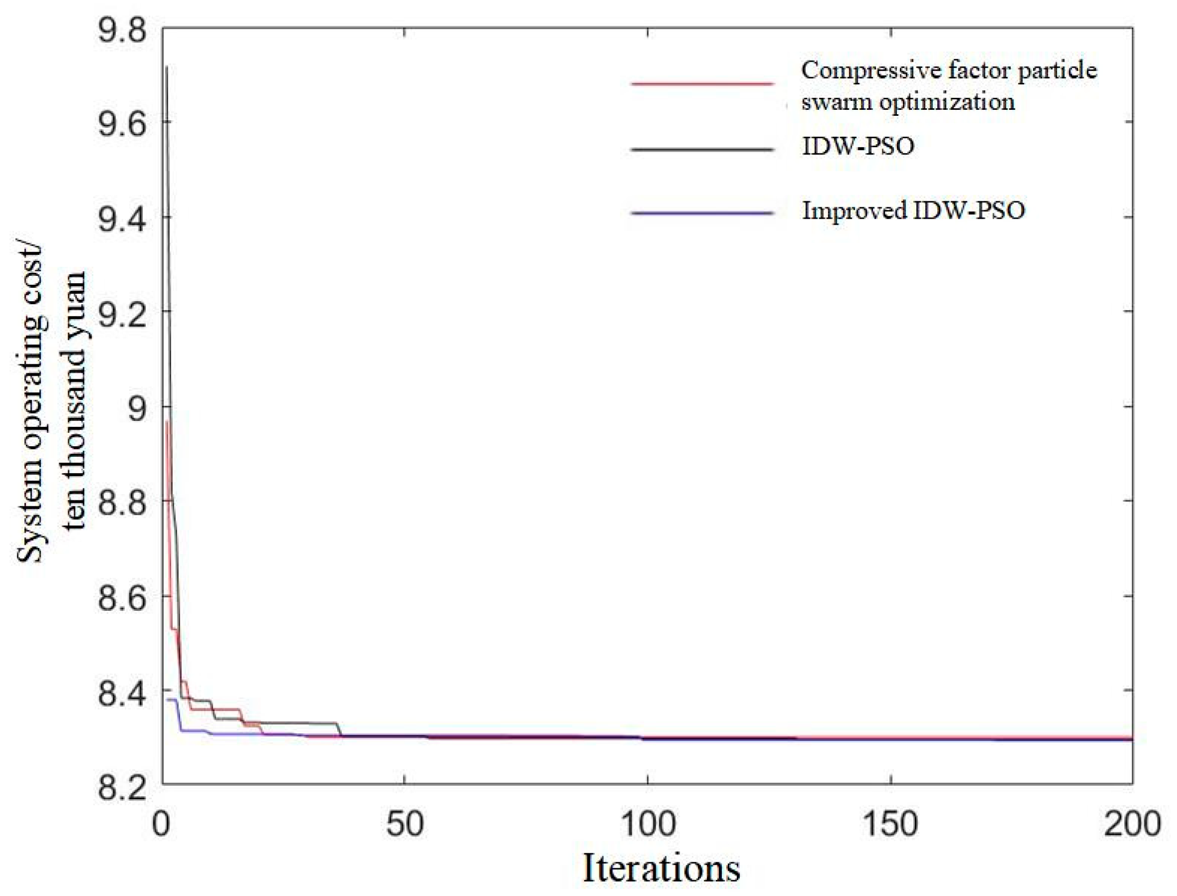
| Algorithm Name | Minimum Operating Cost/Ten Thousand Yuan | Average Number of Iterations | Average Time/s |
|---|---|---|---|
| Compressive factor particle swarm optimization [31] | 8.359 | 150 | 16.12 |
| IDW-PSO | 8.328 | 144 | 15.15 |
| Improved IDW-PSO | 8.326 | 124 | 15.05 |
| Application Scheme | Storage Battery/Unit | Supercapacitor/Unit | Hydrogen Energy Storage/Unit | LPSP | Minimum Cost/Ten Thousand Yuan |
|---|---|---|---|---|---|
| Scheme 1 | 2034 | 28,956 | — | 0.0321 | 8.321 |
| Scheme 3 (Before improvement) | 1975 | — | 127 | 0.0297 | 8.359 |
| Scheme 4 (After improvement) | 1989 | — | 106 | 0.014 | 8.323 |
Disclaimer/Publisher’s Note: The statements, opinions and data contained in all publications are solely those of the individual author(s) and contributor(s) and not of MDPI and/or the editor(s). MDPI and/or the editor(s) disclaim responsibility for any injury to people or property resulting from any ideas, methods, instructions or products referred to in the content. |
© 2023 by the authors. Licensee MDPI, Basel, Switzerland. This article is an open access article distributed under the terms and conditions of the Creative Commons Attribution (CC BY) license (https://creativecommons.org/licenses/by/4.0/).
Share and Cite
He, G.; Wang, Z.; Ma, H.; Zhou, X. Optimal Capacity Configuration of Wind–Solar Hydrogen Storage Microgrid Based on IDW-PSO. Batteries 2023, 9, 410. https://doi.org/10.3390/batteries9080410
He G, Wang Z, Ma H, Zhou X. Optimal Capacity Configuration of Wind–Solar Hydrogen Storage Microgrid Based on IDW-PSO. Batteries. 2023; 9(8):410. https://doi.org/10.3390/batteries9080410
Chicago/Turabian StyleHe, Ge, Zhijie Wang, Hengke Ma, and Xianli Zhou. 2023. "Optimal Capacity Configuration of Wind–Solar Hydrogen Storage Microgrid Based on IDW-PSO" Batteries 9, no. 8: 410. https://doi.org/10.3390/batteries9080410
APA StyleHe, G., Wang, Z., Ma, H., & Zhou, X. (2023). Optimal Capacity Configuration of Wind–Solar Hydrogen Storage Microgrid Based on IDW-PSO. Batteries, 9(8), 410. https://doi.org/10.3390/batteries9080410