Article

Integrated Design of a Functional Composite Electrolyte and Cathode for All-Solid-State Li Metal Batteries

1
School of Materials Science and Engineering, Jiangsu University of Science and Technology, Zhenjiang 212003, China
2
Department of Chemical and Materials Engineering, The University of Auckland, Auckland 1142, New Zealand
*
Authors to whom correspondence should be addressed.
These authors contributed equally to this work.
Batteries 2023, 9(6), 320; https://doi.org/10.3390/batteries9060320
Submission received: 17 April 2023 / Revised: 29 May 2023 / Accepted: 6 June 2023 / Published: 9 June 2023
(This article belongs to the Special Issue Electrode Materials and Electrolyte for Rechargeable Batteries)

Abstract

:
Solid composite electrolytes exhibit tremendous potential for practical all-solid-state lithium metal batteries (ASSLMBs), whereas the interfacial contact between cathode and electrolyte remains a long-standing problem. Herein, we demonstrate an integrated design of a double-layer functional composite electrolyte and cathode (ID-FCC), which effectively improves interfacial contact and increases cycle stability. One composite electrolyte layer, PVDFLiFSI@LLZNTO (PL1@L), comes into contact with the LLZNTO (Li6.5La3Zr1.5Nb0.4Ta0.1O12)-containing cathode, while the other layer, PEOLiTFSI@LLZNTO (PL2@L) with a Li anode, is introduced in each. Such a design establishes a continuous network for the transport of Li+ on the interface, and includes the advantages of both PEO and PVDF for improving stability with the electrodes. The Li symmetric cells Li/PL2@L-PL1@L-PL2@L/Li steadily cycled for more than 3800 h under the current density of 0.05 mA cm−2 at 60 °C. Outstandingly, the all-solid-state batteries of LiFePO4-ID-FCC/Li showed an initial specific capacity of 161.5 mA h g−1 at 60 °C, demonstrating a remaining capacity ratio of 56.1% after 1000 cycles at 0.1 C and 74.5% after 400 cycles at 0.5 C, respectively. This work provides an effective strategy for solid-state electrolyte and interface design towards ASSLMBs with high electrochemical performance.

1. Introduction

Due to flammable liquid organic electrolytes, uncontrollable electrochemical side reactions, and internal short circuits caused by lithium dendrite growth, lithium-ion batteries (LIBs) based on organic liquid electrolytes cannot satisfy the ever-increasing energy storage demands of modern society [1,2,3]. Recently, all-solid-state lithium metal batteries (ASS-LMBs) have delivered high energy density performance by utilizing (electro)chemically stable and non-flammable solid-state electrolytes and lithium metal anodes [4,5]. This has been considered to be a candidate for a next-generation electrochemical energy storage device for high-endurance electric vehicles and large-scale energy storage [6].
The SSEs which determine the overall performance of the batteries have two basic types, namely, inorganic solid electrolytes (ISEs) [7] and solid polymer electrolytes (SPEs) [8]. Many types of ISEs, such as garnet and NASICON-like oxides, thio-LISICON, argyrodites, sulfides, and halides, have been reported exhibiting excellent ionic conductivities (σ, 10−4–10−2 S cm−1, 25 °C), wide electrochemical windows, and excellent mechanical properties [9]. Cubic garnet Li7La3Zr2O12-based oxides are considered to be one of the most practical ISEs, with suitable ionic conductivity and stability to metallic Li, but they suffer from high interfacial resistances and poor contact with the electrodes [10]. Considerable efforts have been made to enhance the ionic conductivity of garnet oxides using a partial substitution approach at single or mixed cationic sites [11,12,13]. Due to the rigidity of oxide electrolytes (such as LLZO and LATP), their contact with the lithium metal anode is poor. The interface design between inorganic ceramic electrolytes and electrodes is therefore critical [14,15]. On the other hand, SPEs have unique advantages in practical applications owing to their good flexibility, softness, wettability, and easy preparation [16,17]. Among them, the electrolyte blending polyethylene oxide (PEO) with amorphous lithium salt has been well studied [18,19,20]. When the temperature goes beyond the glass transition temperature (Tg) of the polymer, lithium ions migrate with the irregular movement of polymer segments. Therefore, lowering the Tg of the polymer is an effective way to increase the ionic conductivity of the polymer [21]. However, polymers have low ionic conductivities and low transference numbers due to their crystallinity, weak salt disassociation, and the strong solvation of Li+ by chains, which limit the application of PEO-based electrolytes [22,23]. Thus, the use of ISEs or SPEs alone cannot achieve the actual demands of all-solid-state batteries.
In recent years, inorganic-polymer hybrid electrolytes (IPHEs) have been reported that can make use of the advantages of both electrolytes [24,25,26]. Thangadurai et al. synthesized a flexible and mechanical film composed of PEO, LiClO4, and LLZO-based garnet oxide fillers as an artificial interlayer to enhance the interfacial contact of the Li anode and the ceramic electrolyte [27]. Nevertheless, it is a challenge for a single layer of IPHE to simultaneously realize dendrite-free Li metal plating and low interface resistance, and enabe a high-voltage cathode. To enable lithium-free dendritic deposition and stable operation at a high-voltage, Zhou et al. reported a cheap double-layer polymer electrolyte PEO–LiTFSI/PMA-LiTFSI, which could stably operate at a voltage of 4 V and maintain good ion conductivity after long-term cycling [28]. He et al. proposed an ultra-thin (4.2 µm) double-layer IPHE consisting of a porous ceramic support and a double-layer Li+ conductive polymer, which enhanced the compatibility of the lithium anode and high-voltage cathode LiNi0.8Co0.1Mn0.1O2 (NCM811) [29].
In this work, we propose an integrated design of a double-layer functional composite electrolyte and cathode (ID-FCC) for ASSLMBs. An additional layer of PVDF-based electrolyte was constructed at the cathode/PEO-based SPE interface, in which the PVDF-based IPHE membrane bonded with the cathode and the PEO-based IPHE membrane comes into contact with the Li anode. As the cathode binder, PVDF is more resistant to high voltage, and its use as a transition layer prevents the slow oxidation of PEO-based SPE at voltages exceeding 3.9 V [30,31,32,33]. At the same time, PVDF as a binder strengthened the binding between the electrolyte and the cathode. In our previous studies, Nb-Ta co-doped cubic garnet Li6.5La3Zr1.5Nb0.4Ta0.1O12 (LLZNTO) manifested excellent ionic conductivity and optimal sinterability [12]. Thus, it was added into the IPHE layers of ID-FCC as a “ceramic in polymer” [34] to enhance the segmental transport of Li+ in the polymer by reducing its crystallinity and enhancing the ionic conductivity of the layers. We demonstrate that Li symmetric cells can be stably cycled over 3800 h at 0.05 mA·cm−2 at 60 °C. The LiFePO4-ID-FCC/Li all-solid-state cell exhibited an initial specific capacity of 161.5 mA h·g−1 (161.7 mA h·g−1 achieved for NCM811-ID-FCC/Li cell) and high capacity retention at 60 °C. The half-solid-state LiFePO4-ID-FCC (2 μL)/Li cell showed an excellent specific capacity of 169.6 mA h·g−1 (0.2 C, 60 °C), which maintained 160.8 mA h·g−1 after 150 cycles. To sum up, this work offers a robust cathode and SSEs integration strategy to simultaneously achieve stable cycling and low interface resistance.

2. Experimental Section

2.1. Materials

PEO (Mv = 6 × 10⁵, Aladdin) and PVDF (Mv = 1 × 10⁶, Arkema) were stored in a vacuum desiccator and dried in a vacuum oven at 50 °C for 24 h before the experiment. LiTFSI (99%, Aladdin) and LiFSI (>98%, Aladdin) were stored in an argon-filled glove box from purchase to application. LiFePO4 powders, polycrystalline NCM811, acetylene black, and carbon-coated aluminum foil (coating thickness 16 μm) were purchased from Hefei Kejing Materials Technology Co., Ltd., Hefei, China; lithium foil (Φ15.6 × 0.45 mm, 99.95%, Guangdong Canrd New Energy Technology Co., Ltd., Guangzhou, China), anhydrous acetonitrile (ACN, >99%, Aladdin), N-1-methyl-2-pyrrolidinone (NMP, 99.5%, Aladdin), and N,N-dimethylformamide (DMF, 99.5%, Aladdin) were used as received.
The cubic Li6.5La3Zr1.5Nb0.4Ta0.1O12 (LLZTNO) powders were synthesized in air from raw materials of LiOH·H2O, La2O3, ZrO2, Nb2O5, and Ta2O5 via a typical solid-state synthesis method we previously reported elsewhere [12]. The synthesis temperature profile of 900 °C for 6 h was designed as per the thermal analysis data shown in Figure S1a.

2.2. Preparation of Cathodes

The LiFePO4 cathode (LFP) was prepared as follows: LiFePO4 powders, acetylene black, PVDF, and LLZNTO were well ground with a weight ratio of 7:1:1:1 in agate mortar and added to an appropriate amount of NMP to obtain a homogeneous slurry using a magnetic stirrer after stirring for 6 h. Then, the cathode slurry was cast on an Al foil with a thickness of 150 μm and dried overnight in a vacuum drying oven at 100 °C. After the organic solvent completely volatilized, the LFP cathode was taken from the oven for use. Finally, after weighing and calculation, the mass loading of the active material LiFePO4 in the cathode was around 1.3 mg cm−2.
Similarly, the high voltage cathode of NCM811 was prepared in the same ratio to acetylene black, PVDF, and LLZNTO and the same way as LFP was. The mass loading of active material NCM811 in the cathode was ca. 1.5 mg cm−2.

2.3. Preparation of ID-FCC and Cells’ Assembly

The integrated design of cathode and double-layer functional inorganic-polymer composite electrolytes (ID-FCC), noted as XXX-ID-FCC, where XXX represents the active material of the cathode, such as LiFePO4 or NCM811, were assembled by the following procedures. Firstly, correct weights of LLZNTO garnet powder, PVDF, and LiFSI were added to the DMF solvent in the glove box, where LLZNTO accounted for 10 wt% of the PVDFLiFSI electrolyte (molar ratio of VDF/Li+ = 11:1), then sealed and transferred out. After 8 h of magnetic stirring at 55 °C, a homogeneous brown solid electrolyte slurry (PL1@L) was obtained. In addition, a uniform PL2@L slurry was prepared via the same proportion of LLZNTO powder and PEOLiTFSI electrolyte, where the molar ratio of EO/Li+ was 8:1. Subsequently, after vacuuming to remove excess bubbles, the PL1@L slurry was directly cast on the dried cathode tape (LiFePO4 or NCM811) via a tape casting method, and dried over 12 h at 55 °C in a vacuum oven to remove the organic solvent. Then, the PL2@L slurry was cast on the dry surface of the PL1@L supported by the cathode foil, and dried in the same way as PL1@L was.
XXX-ID-FCC tapes were subsequently cut into discs with a diameter of 14 mm using a manual puncher in the Ar gas-filled glove box. For comparison, a single-layer integrated structure, LFP-PL2@L, was made using a the similar process, but with only one layer of PL2@L.
The obtained LFP-ID-FCC discs were assembled with 15.6 mm diameter lithium foils in the CR2032-type LFP-ID-FCC/Li full cells at a pressure of 55 kg/cm2. In a similar way, the LFP-PL2@L/Li coin cell was assembled. To further test the performance of ID-FCC, a half-solid-state cell LFP-ID-FCC (2 μL)/Li with 2 μL liquid organic electrolyte was assembled, with the selected specification of 1.0 M LiPF6 in EC:DEC:DMC = 1:1:1 Vol%.

2.4. Material Characterization

The crystal structure and purity of the garnet (LLZNTO) and composite electrolytes were characterized with X-ray diffraction (XRD) using a diffractometer (D2 Phaser, Bruker AXS, Karlsruhe, Germany) with Cu Kα radiation (λ = 1.5418 Å). The tube voltage and current were 30 kV and 10 mA, respectively. The tested range of the 2θ was 10–80°, with a step size of 0.02° and dwelling time of 0.2 s for each step. The morphology and elemental distribution of samples were observed via scanning electron microscope (SEM, JSM-6480, JEOL, Tokyo, Japan) matched with energy-dispersive X-ray spectroscopy (EDS), operated at an acceleration voltage of 20 kV. The functional groups were examined by analyzing the Fourier transform infrared spectroscopy (FT-IR), tested by a Fourier infrared spectrometer (ICAP7400, Thermo Fisher, Waltham, MA, USA). Thermogravimetric-differential scanning calorimetry (TG-DSC) was performed with simultaneous thermal analysis in an Ar atmosphere with a ramp rate of 5 K min−1 on a simultaneous thermal analyzer (STA 449F3, NETZSCH, Bavaria, Germany). The mechanical properties of composite electrolyte membranes were tested using tensile tests with a rate of 4 mm min−1 on a universal testing machine (CMT4304, MTS, Eden Prairie, MN, USA).

2.5. Electrochemical Measurements

The PL1@L slurry was poured into a round glass mold and vacuum dried at 55 °C in an oven for 12 h. After cooling down to room temperature, the obtained PL1@L membrane with a thickness of around 60 μm was stripped off. Similarly, the PL2@L slurry was dropped into a Teflon mold and dried overnight at 55 °C to receive a layer with thickness of ~180 μm. After being peeled off, PL1@L and PL2@L discs were, respectively, assembled by sandwiching between two stainless steel (SS) sheets in a CR2032 cell to measure their ionic conductivities at different temperatures. In addition, a double-layer (PL1@L and PL2@L) inorganic-polymer hybrid electrolyte (hereafter noted as DL@L) membrane with a thickness of ~260 μm was assembled using a repetitive slurry casting–drying method on a round glass mold.
An electrochemical station (Autolab PGSTAT 302N, Metrohm, Herisau, Switzerland) equipped with a high-frequency response analyzer (Autolab ECI 10 M, Metrohm, Herisau, Switzerland) was used to measure the electrochemical impedance spectroscopy (EIS) of the electrolytes. The test was conducted with a frequency range of 10 MHz to 0.1 Hz under a temperature of 25–80 °C. An asymmetric Li/DL@L/Li cell was assembled to measure the lithium ion transference number ( t Li + ) using potentiostatic polarization. The electrochemical stability window was evaluated by assembling Li/DL@L/Fe (stainless steel) cells, which used linear sweep voltammetry (LSV). The cycling performance and rate performance of LiFePO4-ID-FCC/Li all-solid-state cells and NCM811-ID-FCC/Li cells were performed at 60 °C between 2.4 to 4.2 V and 2.5 to 4.3 V on a CT2001A battery test system (LANHE, Wuhan, China), respectively. The Li/PL2@L-PL1@L-PL2@L/Li symmetrical cells were assembled to test the critical current density (CCD) and galvanostatic lithium stripping and plating performance at 60 °C by applying a direct current.

3. Results and Discussion

3.1. Characterization of Composite Membranes

The structure of the ID-FCC and the assembly of the solid-state battery are illustrated in Figure 1a. As described in the Experimental Section, both the PVDFLiFSI@LLZNTO layer (PL1@L) and the PEOLiTFSI@10 wt% LLZNTO layer (PL2@L) consisted of 10 wt% garnet, and were cast onto the cathode one after another via the doctor blade-casting method to form an ID-FCC. A digital photo of an ID-FCC is shown in Figure 1b, with a transparent and flat surface. The cross-sectional SEM image of ID-FCC in Figure 1c illustrates that PL1@L and PL2@L were well bonded and approximately 40 μm each, with a total thickness of about 80 μm for the double layer (DL@L). The surface morphology of the PEOLiTFSI@LLZNTO layer of the as-prepared ID-FCC is shown in Figure 1d. The LLZNTO particle fillers were uniformly distributed in the PEO-based electrolyte (PL2@L).
Figure 2a depicts the XRD patterns of the LLZNTO powder, pure polymers (PEO and PVDF), and inorganic-polymer hybrid electrolytes (IPHEs), including PL1@L and PL2@L. It demonstrates that the as-synthesized LLZNTO has a cubic garnet structure (space group Ia 3 ¯ d) matching well to the PDF card No. 80-0457, which maintained its cubic structure in the IPHEs. In addition, polymers were in a non-crystalline state in the hybrid electrolytes as a result of intermolecular interaction [35], which facilitates the Li+ ion transport of PEO by increasing the chain movement.
To investigate the structural features of PL2@L and PL1@L electrolytes, they were subjected to FT-IR analysis with spectra displayed in Figure 2b and Figure S1b, respectively. It can be seen from Figure 2b that after the addition of LLZNTO, a new vibrational peak at 871 cm−1 appeared in PL2@L. This new peak was characteristic of the C–N functional group, and was probably caused by an interaction between PEO and LiTFSI [36]. Due to the presence of LLZNTO, the TFSI anions could be bound to PEO polymer chains and thus be fixed. This behavior could inhibit the growth of lithium dendrites by inducing a uniform distribution of space charge [37]. The FT-IR spectra of PVDF-based membranes (Figure S1b) showed a new peak at 1661 cm−1 apart from the characteristic vibration peaks at 836, 876, 1231, and 1386 cm−1. This peak represented the C=C functional group generated by the salt-induced dehydrofluorination of PVDF, which is beneficial to the ionic transport [36].
Differential scanning calorimetry (DSC) was performed for these membranes to further determine the functional roles of PL1@L and PL2@L in the cells (Figure 2c). The PVDF phase in the PL1@L electrolyte remained amorphous, and the endothermic peak of PL2@L was 46.55 °C, indicating that the PL2@L electrolyte membrane would be in a molten and peristaltic state above 45 °C. Therefore, at the typical cell operating temperature of 60 °C, PL2@L could be slowly and tightly bonded with the lithium metal anode interface through peristalsis. The good interfacial bonding and the formation of SEI favored the decrease in interface resistance.
It is interesting to note that there was no endothermic peak for DL@L. This phenomenon has been reported in the literature. For instance, Ling et al. [38] reported a double-layer hybrid electrolyte (DL) whose endothermic peak of PEO is hardly seen if compared to the single-layer hybrid electrolyte containing PEO (SL2), although there was no discussion on the possible reasons for this phenomenon. Our speculation is that it may be ascribed to the synergic effect of the double-layered structure and the relatively lower content of PEO in it. The intrinsic reason is worth further investigating in the future.
Since safe operation is particularly important for lithium-ion batteries, we examined the thermal stability and mechanical strength of the electrolytes using TGA analysis and a mechanical tensile test. TGA traces of the PL1@L, PL2@L, and DL@L electrolytes are displayed in Figure 2d. It is evident that the double-layer electrolyte DL@L was more stable than monolayer electrolytes. During the process of heating up to 200 °C, a small amount of mass loss is caused by the volatilization of adsorbed water and organic solvent, and weight retention rates of 81.2, 88.0, and 94.3%, respectively, were obtained at an elevated temperature of 200 °C. The polymer components and Li salts in the electrolytes decomposed at temperatures beyond 200 °C far exceeded the typical operating temperature 60 °C of ASSBs. Figure S1c shows the stress–strain curves of PL1@L, PL2@L, and DL@L electrolyte membranes. The tensile strength of PL2@L (PEO-based) was only 1.3 MPa, while PL1@L (PVDF-based) had a tensile strength of 11.9 MPa and a maximum strain of 360% due to its high toughness and strength, which were much higher than PL2@L. Through a simple double-layer integrated design, the strength of DL@L reached 3.9 MPa and the strain exceeded 180%. Compared to the conventional single-layer PEO-based hybrid electrolyte membrane, the addition of an extra layer of PVDF-based membrane with a higher strength played the role of enhancing the strength of the PEO matrix, also improving its ability to inhibit the growth of lithium dendrites.

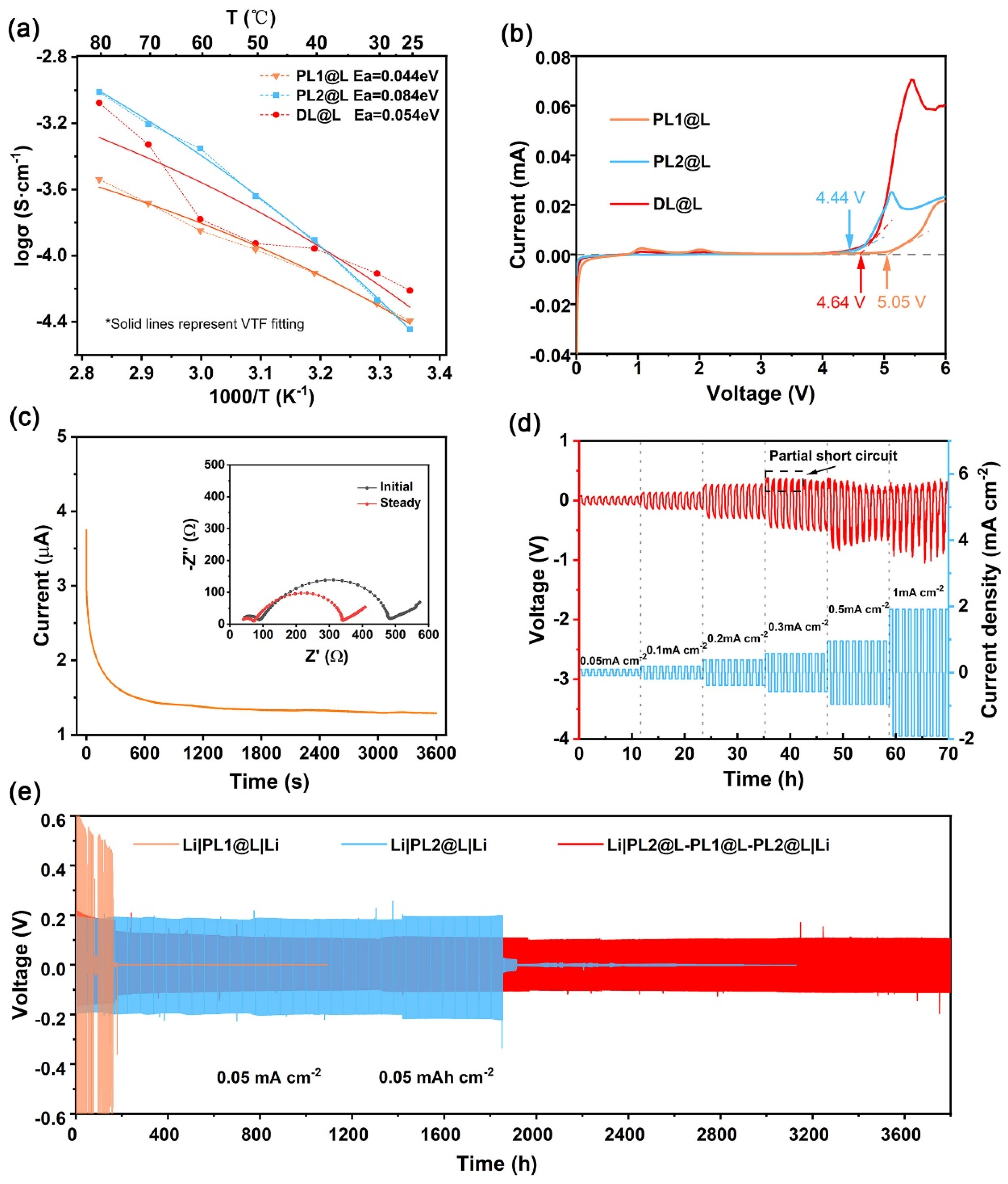
3.2. Electrochemical Characterization of Composite Membranes

The relationship between the ionic conductivity and temperature of PL1@L, PL2@L, and DL@L at 25–80 °C are displayed in Figure 3a, and their corresponding EIS curves and ionic conductivity charts are shown in Figure S2. The ionic conductivities of PL1@L and PL2@L at 60 °C were around 1.42 × 10⁻⁴ S cm−1 and 4.44 × 10⁻⁴ S cm−1, respectively, whereas that of DL@L was in between (1.66 × 10⁻⁴ S cm−1). In addition, by fitting the curves using the Vogel–Tamman–Fulcher (VTF) equation (Equation (1)) [39], the activation energy Ea of the DL@L could be calculated to be 5.4 × 10⁻² eV, which was between that of PL1@L (4.4 × 10⁻² eV) and PL2@L (8.4 × 10⁻² eV). Evidently, electrolytes exhibit a lower conductivity at room temperature (3.98 × 10⁻⁵, 3.60 × 10⁻⁵, and 4.08 × 10⁻⁵ S cm−1 for PL1@L, PL2@L, and DL@L, respectively), yet much higher than that of PEOLiTFSI polymer electrolyte (~1 × 10⁻⁶ S cm−1).
σ = σ 0 T 1 2 exp { E a k B ( T T 0 ) }
Linear sweep voltammetry (LSV) measurements were carried out at room temperature in the voltage range from 0 to 6 V (vs. Li+/Li) at a sweep rate of 0.1 mV s−1, and the corresponding profiles are shown in Figure 3b. The oxidation peaks of PL1@L and PL2@L appeared at 5.05 V and 4.44 V vs. Li+/Li, respectively, whereas DL@L exhibited an oxidation peak in between (4.64 V vs. Li+/Li). All three showed a wider window of electrochemical stability at room temperature when compared with liquid organic electrolytes. The LSV curve of a Li/DL@L/Fe (SS) cell in Figure S3a shows a pair of oxidation-reduction peaks appearing near 0 V, corresponding to the electrochemical processes of Li+ plating and stripping. The small peak at 1 V was due to the slight current change caused by the consumption of Li by irreversible SEI substances formed at the PCE/Li interface. In addition, LiFePO4 was adopted as an active material for the fabrication of the integrated structure of the cathode and DL@L (LFP−ID-FCC), and further assembled into an all-solid-state cell with a metallic Li anode. The CV curves for the first three cycles in Figure S3b have similar redox peaks of LiFePO4, illustrating that the LFP−ID-FCC/Li all-solid-state cell exhibits good reversibility.
The potentiostatic polarization method was applied to measure the lithium-ion transference number ( t Li + ) of the DL@L electrolyte at 60 °C, and the result is shown in Figure 3c, where the inset illustrates the impedance change before and after the polarization test at the voltage of 10 mV. By calculating using the Bruce−Vincent method in Equation (S1), the DL@L electrolyte had a lithium-ion transference number of 0.304, and the corresponding value is shown in Table S1. This was significantly higher than that of PEO-LiTFSI composite electrolytes (≤0.2). The increase in transference number can be attributed to the fact that the lithium-ion conductor LLZNTO provides an additional pathway for lithium-ion transport, which perhaps blocks the TFSI anion migration by way of the Lewis acid−base interaction between the TFSI anions and LLZNTO [24]. Figure 3d shows the rate testing results of the Li-Li symmetric cell. As the current elevated, the voltage increased linearly and the polarization became more and more serious. The voltage started to become unstable and slightly decreased, with a current density at 0.3 mA cm−2, indicating that lithium dendrites began to grow and partially permeate. Nevertheless, there was no voltage sharp drop or short circuit, although the current density reached 1 mA cm−2.
Long cycle measurements for the stripping and plating behaviors of the lithium-ion were carried out to analyze the cycle stability of the double-layer composite electrolyte to the lithium metal anode in the symmetric cells. The galvanostatic cycling of the composite electrolytes was tested at 60 °C with a current density of 0.05 mA cm−2. The PL2@L-PL1@L-PL2@L triple-layer electrolyte was prepared to investigate the dendrite suppression behavior, which could simulate the evaluation of the effectiveness of the ID-FCC on the suppression of lithium dendrites. As shown in Figure 3e, the Li/PL2@L−PL1@L−PL2@L/Li symmetric cell retained a long-term stable cycle of over 3800 h with 150 mV polarization voltage, while its counterpart, the Li/PL2@L/Li cell, showed an abruptly short circuit after maintaining stable cycling for 1800 h (Figure S4b). The higher polarization voltage observed here was mainly due to the larger thickness of the PL2@L composite electrolyte, which was preferred for the convenient handling of PEO-based electrolytes during the manufacturing process. Obvious voltage changes at the initial cycling stage (Figure S4a) were observed, which may have resulted from the non-uniform Li deposition and the formation of an SEI-like substance at the double-layer composite electrolyte/lithium metal anode interface. This behavior could increase the potential of the symmetric cells in the initial cycles by increasing the cells’ interfacial resistance. After the formation of a stable interface, the voltage curve tends to be steady, thus proving that this electrolyte is stable against the lithium anode. The SEM images in Figure S5 present the accumulation of lithium during the long cycling and the gradual formation of lithium-dendrite at the interface of the ID-FCC/Li.

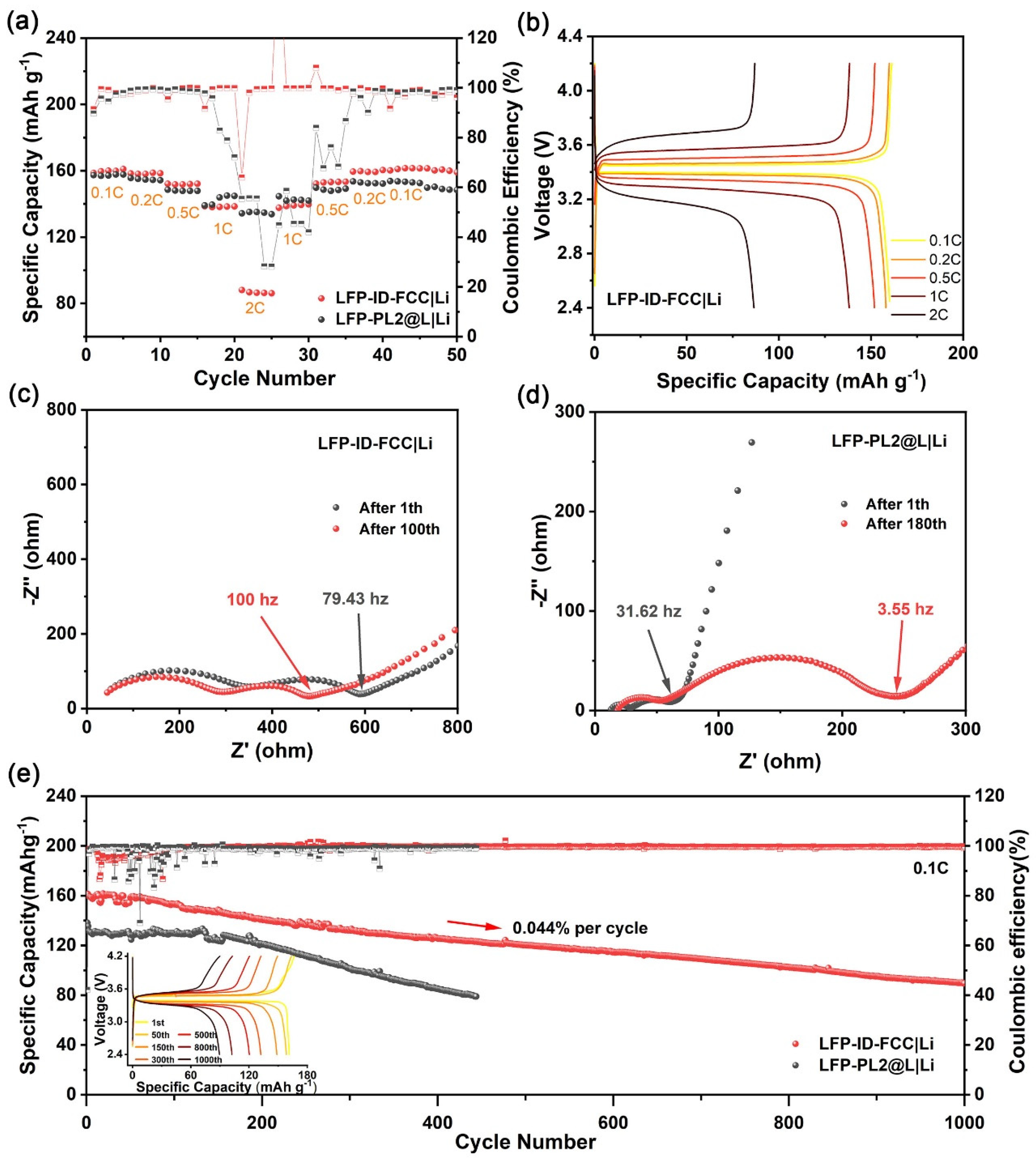
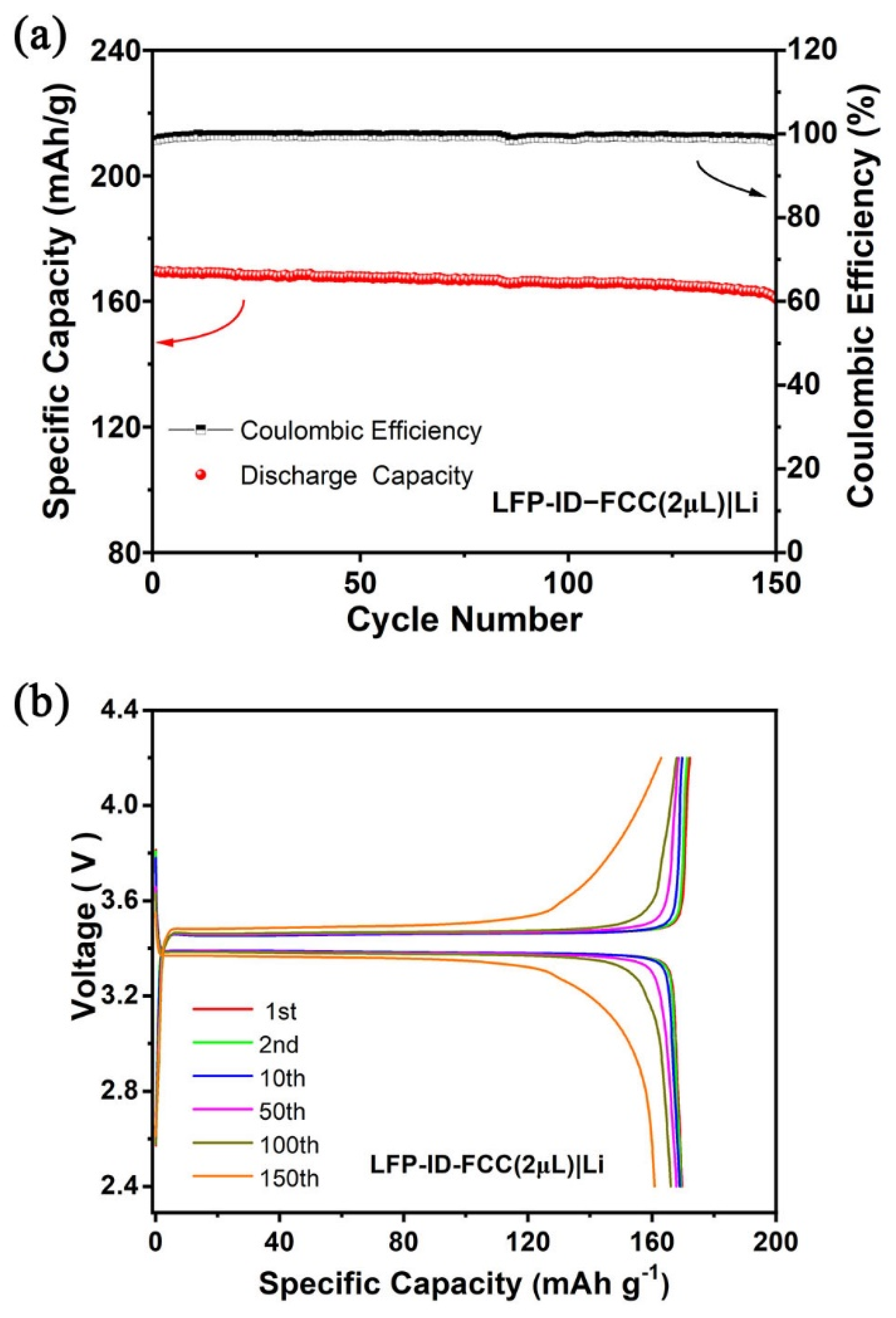
3.3. Performance of Composite Membranes in Full Cell

In order to further explore the application of the integrated design of ID-FCC, all-solid-state lithium batteries were assembled using LiFePO4 or NCM811 as a cathode and the lithium metal as an anode.
The rate performance results are shown in Figure 4a, which demonstrates the rate capability at a current density range of 0.1 C to 2 C (1 C = 170 mA g−1) at 60 °C. For LFP−ID-FCC/Li, they demonstrate average discharge capacities of 159.8, 151.9, and 86.7 mA h g−1 at rates of 0.1 C, 0.5 C, and 2 C, respectively. When the rate was switched back to 0.1 C, the capacity fully recovered, exhibiting a good tolerance to charge/discharge rate changes. For the LFP−PL2@L/Li cell, it had a capacity of 157.4, 149.3, and 134.6 mA h g−1 at the different rates of 0.1 C, 0.5 C, and 2 C, respectively. Although the discharge capacity of the LFP−PL2@L/Li cell at 1 C and 2 C was higher than the LFP−ID-FCC/Li cell, it was unstable and the coulomb efficiency dropped seriously, even below 30%. When the rate gradually reduced to 0.1 C, the discharge capacity was still unstable and lower than the previous level, presenting a poor rate performance.
Figure 4b presents the galvanostatic charge−discharge (GCD) curves of the LFP−ID-FCC/Li cell at different rates, ranging from 0.1 to 2 C. The steady charging and discharging platforms suggest a stable electrochemical process inside the batteries. The discharge capacity of the LFP−ID-FCC/Li cell was comparable with the charge capacity, resulting in a corresponding Coulombic efficiency of >99.1%. By contrast, the GCD curves of the LFP-PL2@L/Li cell under the same testing conditions are shown in Figure S6. Significant overcharge was observed at the rate of 1 C and 2 C, which was responsible for the extremely low Coulomb efficiency. This phenomenon could be attributed to reactions at the SPE/Li interface. In particular, micro-shorts caused by the formation of dendritic lithium during the charging process, which would seem to be the responsible failure source [40].
The EIS spectra of the LFP−ID-FCC/Li and LFP−PL2@L/Li cells acquired at 60 °C are shown in Figure 4c,d. Both spectra consist of two suppressed semicircles representing the surface resistance (Rf) and charge transfer resistance (Rct), respectively, and a slash line of Warburg diffusion (Wo). It can be seen in Figure 4c that, after 100 cycles, the impedance semicircles shifted to the left and the overall impedance decreased. Apparently, with cycling the overall ionic conductivity raises as the cyclic interface contact is slowly improved. This also confirms that the LFP−Li system is compatible with the integrated structure of the double-layer IPHE electrolytes. In contrast, the impedance of the LFP-PL2@L/Li cell was increased from 63 Ω after the first cycle to 240 Ω after 180 cycles (Figure 4d), which led to poor cycle performance.
As shown in Figure 4e, the LFP−ID-FCC/Li all-solid-state cell manifested excellent cycle performance at 0.1 C at 60 °C. The initial specific capacity was 161.5 mA h g−1, and the capacity retention was 78.7% after 400 cycles and 56.1% after 1000 cycles. The average decay rate of discharge capacity per cycle was only 0.044% and the Coulombic efficiency gradually increased to a stable trend, indicating that the electrochemical system inside the full battery tended to be relatively stable. The polarization evolution of the double-layer composite electrolyte resembled that of the polymer electrolyte, displaying an unstable Coulombic efficiency in the initial cycles and revealing the formation of unstable SEI. In contrast, the initial specific capacity of the LFP−PL2@L/Li cell was only 138.2 mA h g−1, and the Coulombic efficiency was unstable during the entire cycle performance test. As the charge–discharge cycles progressed, the specific capacity decayed significantly to be only 84.6 mA h g−1 after 400 cycles, with a retention rate of only 61.2%. Figure 4e inset shows the typical charge–discharge curves of LFP−ID-FCC/Li cell.
To evaluate the cycle performance of the LFP−ID-FCC/Li cell at a high rate, it was tested at 0.5 C under 60 °C, as shown in Figure S7a. The LFP−PL2@L/Li cell was also tested as a control experiment. The discharge specific capacity of the LFP−ID-FCC/Li cell after the first two cycles of activation was 130.2 mA h g−1, and this slowly increased to 142.1 mA h g−1 in the first 90 cycles. This phenomenon has also been observed in the LFP−PL2@L/Li cell. The excessive current density and initial internal structure instability may be accountable to the serious electrolyte potential polarization and the insufficient transfer of lithium ions to the cathode. When the internal structure stabilized, the capacity rose to the maximum and then, normally, declined with cycling. It had a capacity of 105.9 mA h g−1 after 400 cycles, and the capacity retention was 74.5% after 310 cycles, from the 90th to the 400th cycle, with an average Coulombic efficiency of over 99.7%. Differently from LFP−ID-FCC/Li cell, although the discharge capacity of the LFP−PL2/Li cell was higher, the capacity of the third cycle was 139.3 mA h g−1 and the 24th cycle reached the maximum of 159.1 mA h g−1; however, the Coulomb efficiency dropped sharply to 20% and lower, indicating that the serious formation of lithium dendrites occurred at the SPE/Li anode interface [40]. It was evidenced that LFP−ID-FCC/Li cell had excellent cyclic stability relative to the LFP−PL2@L/Li cell at a higher rate.
Table 1 compares the material design, processing, discharge capacity, and capacity retention of all-solid-state lithium metal batteries from IPHE- and LFP-based cathodes in the literature and this work. It shows that the integrated design of the double-layer functional composite electrolyte PEOLiTFSI-LLZNTO/PVDFLiFSI-LLZNTO and the cathode LFPLLZNTO (ID-FCC) herein reported exhibited a high discharge capacity at 0.1 C, long cycle stability, and comparable (or even higher) capacity retention rates, if relevant, to those reported in the literature.
Per the above discussion, it is believed that the main reasons for the degradation of battery capacity could be the high resistance, the growth of lithium dendrites, and the uneven SEI of the interface where the PEO-based composite electrolyte contacts the Li-anode. To verify this, a semi-solid-state LFP−ID-FCC (2 μL)/Li battery was assembled and the cycle performance (Figure 5a) and GCD tests (Figure 5b) of the cell were conducted at 60 °C and 0.2 C. This enabled an initial specific capacity of 169.6 mA h g−1 and a capacity retention of 94.8% after 150 cycles. Clearly, better interface contact and lower interface resistance are crucial for high-performance solid-state lithium metal batteries. It is worth noting that there was no liquid electrolyte in either of the all-solid-state cells mentioned in this work. It will be of great interest to study the interface design of the Li anode and the electrolyte and to further improve the mass loading of the active material in the cathode in our future work.
Apart from the LiFePO4 cathode, the applicability of this double-layer functional structure integrated design on the high-voltage cathode NCM811 was further evaluated by assembling an NCM811−ID-FCC/Li cell (Figure S8). The rate performance shown in Figure S8a displays that there was still more than 99% coulomb efficiency at 2 C. Figure S8b delivers an initial specific capacity of 161.7 mA h g−1 and a capacity retention of 56.2% after 80 cycles at 0.1 C, which is 115.7 mA h g−1 and 58.0% after 80 cycles at 0.2 C (Figure S8c). It is a feasible cathode-electrolyte integrated design for the NCM811-based cell to obtain a relatively stable cycle performance, because the slow oxidation and decomposition at the voltage exceeding 3.9 V of the PEO-based composite electrolyte happened when it came into contact with the cathode [40]. Owing to the synergistic effect between the resistance to high voltage of the PL1@L and the outstanding wettability of the PL2@L, the all-solid-state NCM811 battery using an ID-FCC structure had better cycle stability than using PL1@L and PL2@L alone.

4. Conclusions

In summary, an integrated design of a double-layer functional composite electrolyte and cathode (ID-FCC) was constructed via a casting-coating-drying process, and possessed low interfacial impedance and high cycling stability. To be specific, the first layer of PVDFLiFSI@LLZNTO (PL1@L) was designed on the cathode side to avoid the oxidation of the PEO-based polymer electrolyte and widen its electrochemical window. The second layer of PEOLiTFSI@LLZNTO (PL2@L) improved the interfacial contact with metallic Li and prevented the side reactions between the PL1@L with the Li anode. As a result, the Li/PL2@L−PL1@L−PL2@L/Li symmetric cell stably cycled over 3800 h without a short circuit at 0.05 mA cm−2 at a temperature of 60 °C. The assembled LFP−ID-FCC/Li all-solid-state coin cell exhibited an excellent cycle performance, exhibiting an initial specific capacity of 161.5 mA h g−1 and a residual capacity of 56.1% after 1000 cycles at 0.1 C and 60 °C, and presented better cycling stability comparing to the single-layered PL2@L. Even at the rate of 0.5 C, it maintained good performance and stably cycled for over 400 cycles. This work provides a simple and feasible method for the large-scale preparation of IPHEs. The prepared inorganic-polymer hybrid electrolytes (IPHEs) with high stability, a wide electrochemical window, and low interfacial impedance demonstrated their great potential for the fabrication of high-performance, all-solid-state lithium metal batteries.

Supplementary Materials

The following supporting information can be downloaded at: https://www.mdpi.com/article/10.3390/batteries9060320/s1, Table S1: Potentiostatic polarization data of the Li/DL@L/Li cell; Figure S1: TG-DSC curve, FT−IR spectra and mechanical tensile stress–strain curves; Figure S2: EIS spectra and ionic conductivity of composite electrolytes; Figure S3: Cyclic voltammetry (CV) curve of cells; Figure S4: voltage profile of symmetric cells; Figure S5: SEM images of ID-FCC membrane after cycling; Figure S6: Galvanostatic charge–discharge voltage profiles of LFP−PL2@L/Li at different rates; Figure S7: Cycling performances and Galvanostatic charge–discharge voltage profiles of batteries; Figure S8: Rate performance and cycle performance of NCM811−ID-FCC/Li.

Author Contributions

Conceptualization, methodology and writing—review and editing, S.H. and X.S.; resources and software, S.H. and P.C.; investigation, visualization and writing—original draft preparation, Z.Z. and R.F.; validation and formal analysis, J.Z.; data curation, Y.Z., W.D. and C.Z.; supervision, project administration and funding acquisition, S.H. All authors have read and agreed to the published version of the manuscript.

Funding

This research was funded by Jiangsu Specially Appointed Professorship Foundation (Grant No. 1064902003) and the Postgraduate Research and Practice Innovation Program of Jiangsu Province (Grant No. KYCX22_3800).

Data Availability Statement

Data available on reasonable request from the authors.

Conflicts of Interest

The authors declare no conflict of interest.

References

  1. Tarascon, J.M.; Armand, M. Issues and challenges facing rechargeable lithium batteries. Nature 2001, 414, 359–367. [Google Scholar] [CrossRef]
  2. Goodenough, J.B.; Park, K.-S. The Li-ion rechargeable battery: A perspective. J. Am. Chem. Soc. 2013, 135, 1167–1176. [Google Scholar] [CrossRef]
  3. Goodenough, J.B. How we made the Li-ion rechargeable battery. Nat. Electron. 2018, 1, 204. [Google Scholar] [CrossRef] [Green Version]
  4. Hu, Y.-S. Batteries: Getting solid. Nat. Energy 2016, 1, 16042. [Google Scholar] [CrossRef]
  5. Janek, J.; Zeier, W.G. A solid future for battery development. Nat. Energy 2016, 1, 16141. [Google Scholar] [CrossRef]
  6. Ji, X.; Hou, S.; Wang, P.; He, X.; Piao, N.; Chen, J.; Fan, X.; Wang, C. Solid-state electrolyte design for lithium dendrite suppression. Adv. Mater. 2020, 32, 2002741. [Google Scholar] [CrossRef]
  7. Famprikis, T.; Canepa, P.; Dawson, J.A.; Islam, M.S.; Masquelier, C. Fundamentals of inorganic solid-state electrolytes for batteries. Nat Mater 2019, 18, 1278–1291. [Google Scholar] [CrossRef]
  8. Wang, H.; Sheng, L.; Yasin, G.; Wang, L.; Xu, H.; He, X. Reviewing the current status and development of polymer electrolytes for solid-state lithium batteries. Energy Storage Mater. 2020, 33, 188–215. [Google Scholar] [CrossRef]
  9. Huang, S.; Cao, P. Solid-state inorganic electrolytes (oxides, sulfides, and halides). In Advanced Ceramics for Energy Storage, Thermoelectrics and Photonics; Cao, P., Chen, Z.-G., Xia, Z., Eds.; Elsevier: Amsterdam, The Netherlands, 2023; Chapter 4. [Google Scholar]
  10. Raju, M.M.; Altayran, F.; Johnson, M.; Wang, D.; Zhang, Q. Crystal Structure and Preparation of Li7La3Zr2O12 (LLZO) Solid-State Electrolyte and Doping Impacts on the Conductivity: An Overview. Electrochem 2021, 2, 390–414. [Google Scholar] [CrossRef]
  11. Cao, S.; Song, S.; Xiang, X.; Hu, Q.; Zhang, C.; Xia, Z.; Xu, Y.; Zha, W.; Li, J.; Gonzale, P.M.; et al. Modeling, Preparation, and Elemental Doping of Li7La3Zr2O12 Garnet-Type Solid Electrolytes: A Review. J. Korean Ceram. Soc. 2019, 56, 111–129. [Google Scholar] [CrossRef] [Green Version]
  12. Song, X.; Zhang, T.; Christopher, T.D.; Guo, Y.; Huang, S.; Liu, Y.; Söhnel, T.; Cao, P. Achieving enhanced densification and superior ionic conductivity of garnet electrolytes via a co-doping strategy coupled with pressureless sintering. J. Eur. Ceram. Soc. 2022, 42, 5023–5028. [Google Scholar] [CrossRef]
  13. Zhang, T.; Christopher, T.D.; Huang, S.; Söhnel, T.; Liu, Y.g.; Cao, P. Electrochemical properties of Li6+yLa3−yBayNbZrO12 lithium garnet oxide solid-state electrolytes with co-doping barium and zirconium. J. Alloys Compd. 2021, 862, 158600. [Google Scholar] [CrossRef]
  14. Luo, S.; Wang, Z.; Fan, A.; Liu, X.; Wang, H.; Ma, W.; Zhu, L.; Zhang, X. A high energy and power all-solid-state lithium battery enabled by modified sulfide electrolyte film. J. Power Sources 2021, 485, 229325. [Google Scholar] [CrossRef]
  15. Alexander, G.V.; Indu, M.; Kamakshy, S.; Murugan, R. Development of stable and conductive interface between garnet structured solid electrolyte and lithium metal anode for high performance solid-state battery. Electrochim. Acta 2020, 332, 135511. [Google Scholar] [CrossRef]
  16. Zhou, D.; Shanmukaraj, D.; Tkacheva, A.; Armand, M.; Wang, G. Polymer electrolytes for lithium-based batteries: Advances and prospects. Chem 2019, 5, 2326–2352. [Google Scholar] [CrossRef]
  17. Dong, D.; Zhou, B.; Sun, Y.; Zhang, H.; Zhong, G.; Dong, Q.; Fu, F.; Qian, H.; Lin, Z.; Lu, D. Polymer electrolyte glue: A universal interfacial modification strategy for all-solid-state Li batteries. Nano Lett. 2019, 19, 2343–2349. [Google Scholar] [CrossRef]
  18. Yang, L.; Wang, Z.; Feng, Y.; Tan, R.; Zuo, Y.; Gao, R.; Zhao, Y.; Han, L.; Wang, Z.; Pan, F. Flexible composite solid electrolyte facilitating highly stable “soft contacting” Li–electrolyte interface for solid state lithium-ion batteries. Adv. Energy Mater. 2017, 7, 1701437. [Google Scholar] [CrossRef]
  19. Kim, S.-H.; Choi, K.-H.; Cho, S.-J.; Choi, S.; Park, S.; Lee, S.-Y. Printable solid-state lithium-ion batteries: A new route toward shape-conformable power sources with aesthetic versatility for flexible electronics. Nano Lett. 2015, 15, 5168–5177. [Google Scholar] [CrossRef]
  20. Porcarelli, L.; Shaplov, A.S.; Bella, F.; Nair, J.R.; Mecerreyes, D.; Gerbaldi, C. Single-ion conducting polymer electrolytes for lithium metal polymer batteries that operate at ambient temperature. ACS Energy Lett. 2016, 1, 678–682. [Google Scholar] [CrossRef]
  21. Mindemark, J.; Lacey, M.J.; Bowden, T.; Brandell, D. Beyond PEO—Alternative host materials for Li+-conducting solid polymer electrolytes. Prog. Polym. Sci. 2018, 81, 114–143. [Google Scholar] [CrossRef]
  22. Fullerton-Shirey, S.K.; Maranas, J.K. Effect of LiClO4 on the structure and mobility of PEO-based solid polymer electrolytes. Macromolecules 2009, 42, 2142–2156. [Google Scholar] [CrossRef]
  23. Pożyczka, K.; Marzantowicz, M.; Dygas, J.R.; Krok, F. Ionic conductivity and lithium transference number of poly (ethylene oxide): LiTFSI system. Electrochim. Acta 2017, 227, 127–135. [Google Scholar] [CrossRef]
  24. Nkosi, F.P.; Valvo, M.; Mindemark, J.; Dzulkurnain, N.A.; Hernández, G.; Mahun, A.; Abbrent, S.; Brus, J.; Kobera, L.; Edström, K. Garnet-Poly(ε-caprolactone-co-trimethylene carbonate) Polymer-in-Ceramic Composite Electrolyte for All-Solid-State Lithium-Ion Batteries. ACS Appl. Energy Mater. 2021, 4, 2531–2542. [Google Scholar] [CrossRef]
  25. Xie, H.; Yang, C.; Fu, K.K.; Yao, Y.; Jiang, F.; Hitz, E.; Liu, B.; Wang, S.; Hu, L. Flexible, Scalable, and Highly Conductive Garnet-Polymer Solid Electrolyte Templated by Bacterial Cellulose. Adv. Energy Mater. 2018, 8, 1703474. [Google Scholar] [CrossRef]
  26. Li, Y.; Wong, K.W.; Ng, K.M. Li7La3Zr2O12 ceramic nanofiber-incorporated composite polymer electrolytes for lithium metal batteries. J. Mater. Chem. A 2016, 52, 4369–4372. [Google Scholar] [CrossRef]
  27. Pervez, S.A.; Ganjeh-Anzabi, P.; Farooq, U.; Trifkovic, M.; Roberts, E.P.; Thangadurai, V. Fabrication of a Dendrite-Free all Solid-State Li Metal Battery via Polymer Composite/Garnet/Polymer Composite Layered Electrolyte. Adv. Mater. Interfaces 2019, 6, 1900186. [Google Scholar] [CrossRef]
  28. Zhou, W.; Wang, Z.; Pu, Y.; Li, Y.; Xin, S.; Li, X.; Chen, J.; Goodenough, J.B. Double-layer polymer electrolyte for high-voltage all-solid-state rechargeable batteries. Adv. Mater. 2019, 31, 1805574. [Google Scholar] [CrossRef] [PubMed]
  29. He, F.; Tang, W.; Zhang, X.; Deng, L.; Luo, J. High energy density solid state lithium metal batteries enabled by sub-5 µm solid polymer electrolytes. Adv. Mater. 2021, 33, 2105329. [Google Scholar] [CrossRef]
  30. Aurbach, D.; Talyosef, Y.; Markovsky, B.; Markevich, E.; Zinigrad, E.; Asraf, L.; Gnanaraj, J.S.; Kim, H.-J. Design of electrolyte solutions for Li and Li-ion batteries: A review. Electrochim. Acta 2004, 50, 247–254. [Google Scholar] [CrossRef]
  31. Ma, J.; Liu, Z.; Chen, B.; Wang, L.; Yue, L.; Liu, H.; Zhang, J.; Liu, Z.; Cui, G. A strategy to make high voltage LiCoO2 compatible with polyethylene oxide electrolyte in all-solid-state lithium ion batteries. J. Electrochem. Soc. 2017, 164, A3454. [Google Scholar] [CrossRef]
  32. Aurbach, D.; Granot, E. The study of electrolyte solutions based on solvents from the “glyme” family (linear polyethers) for secondary Li battery systems. Electrochim. Acta 1997, 42, 697–718. [Google Scholar] [CrossRef]
  33. Xia, Y.; Fujieda, T.; Tatsumi, K.; Prosini, P.P.; Sakai, T. Thermal and electrochemical stability of cathode materials in solid polymer electrolyte. J. Power Sources 2001, 92, 234–243. [Google Scholar] [CrossRef]
  34. Chen, L.; Li, Y.; Li, S.-P.; Fan, L.-Z.; Nan, C.-W.; Goodenough, J.B. PEO/garnet composite electrolytes for solid-state lithium batteries: From “ceramic-in-polymer” to “polymer-in-ceramic”. Nano Energy 2018, 46, 176–184. [Google Scholar] [CrossRef]
  35. Song, X.; Zhang, T.; Huang, S.; Mi, J.; Zhang, Y.; Travas-Sejdic, J.; Turner, A.P.; Gao, W.; Cao, P. Constructing a PVDF-based composite solid-state electrolyte with high ionic conductivity Li6.5La3Zr1.5Ta0.1Nb0.4O12 for lithium metal battery. J. Power Sources 2023, 564, 232849. [Google Scholar] [CrossRef]
  36. Zhang, X.; Liu, T.; Zhang, S.; Huang, X.; Xu, B.; Lin, Y.; Xu, B.; Li, L.; Nan, C.-W.; Shen, Y. Synergistic coupling between Li6.75La3Zr1.75Ta0.25O12 and poly (vinylidene fluoride) induces high ionic conductivity, mechanical strength, and thermal stability of solid composite electrolytes. J. Am. Chem. Soc. 2017, 139, 13779–13785. [Google Scholar] [CrossRef]
  37. Zhao, C.Z.; Zhang, X.Q.; Cheng, X.B.; Zhang, R.; Xu, R.; Chen, P.Y.; Peng, H.J.; Huang, J.Q.; Zhang, Q. An anion-immobilized composite electrolyte for dendrite-free lithium metal anodes. Proc. Natl. Acad. Sci. USA 2017, 114, 11069–11074. [Google Scholar] [CrossRef] [Green Version]
  38. Ling, H.; Shen, L.; Huang, Y.; Ma, J.; Chen, L.; Hao, X.; Zhao, L.; Kang, F.; He, Y.B. Integrated Structure of Cathode and Double-Layer Electrolyte for Highly Stable and Dendrite-Free All-Solid-State Li-Metal Batteries. ACS Appl. Mater. Interfaces 2020, 12, 56995–57002. [Google Scholar] [CrossRef]
  39. Croce, F.; Focarete, M.L.; Hassoun, J.; Meschini, I.; Scrosati, B. A safe, high-rate and high-energy polymer lithium-ion battery based on gelled membranes prepared by electrospinning. Energy Environ. Sci. 2011, 4, 921–927. [Google Scholar] [CrossRef]
  40. Homann, G.; Stolz, L.; Nair, J.; Laskovic, I.C.; Winter, M.; Kasnatscheew, J. Poly(ethylene oxide)-based electrolyte for solid-state-lithium-batteries with high voltage positive electrodes: Evaluating the role of electrolyte oxidation in rapid cell failure. Sci. Rep. 2020, 10, 4390. [Google Scholar] [CrossRef] [Green Version]
  41. Liu, K.; Zhang, R.; Sun, J.; Wu, M.; Zhao, T. Polyoxyethylene (PEO)|PEO-Perovskite|PEO Composite Electrolyte for All-Solid-State Lithium Metal Batteries. ACS Appl. Mater. Interfaces 2019, 11, 46930–46937. [Google Scholar] [CrossRef]
  42. Zhang, J.; Zhao, N.; Zhang, M.; Li, Y.; Chu, P.K.; Guo, X.; Di, Z.; Wang, X.; Li, H. Flexible and ion-conducting membrane electrolytes for solid-state lithium batteries: Dispersion of garnet nanoparticles in insulating polyethylene oxide. Nano Energy 2016, 28, 447–454. [Google Scholar] [CrossRef]
  43. Yan, C.; Zhu, P.; Jia, H.; Zhu, J.; Selvan, R.K.; Li, Y.; Dong, X.; Du, Z.; Angunawela, I.; Wu, N.; et al. High-Performance 3-D Fiber Network Composite Electrolyte Enabled with Li-Ion Conducting Nanofibers and Amorphous PEO-Based Cross-Linked Polymer for Ambient All-Solid-State Lithium-Metal Batteries. Adv. Fiber Mater. 2019, 1, 46–60. [Google Scholar] [CrossRef] [Green Version]
  44. Huo, H.; Zhao, N.; Sun, J.; Du, F.; Li, Y.; Guo, X. Composite electrolytes of polyethylene oxides/garnets interfacially wetted by ionic liquid for room-temperature solid-state lithium battery. J. Power Sources 2017, 372, 1–7. [Google Scholar] [CrossRef]
  45. Falco, M.; Castro, L.; Nair, J.R.; Bella, F.; Bardé, F.; Meligrana, G.; Gerbaldi, C. UV-Cross-Linked Composite Polymer Electrolyte for High-Rate, Ambient Temperature Lithium Batteries. ACS Appl. Energy Mater. 2019, 2, 1600–1607. [Google Scholar] [CrossRef]
  46. Wu, M.; Liu, D.; Qu, D.; Xie, Z.; Li, J.; Lei, J.; Tang, H. 3D Coral-like LLZO/PVDF Composite Electrolytes with Enhanced Ionic Conductivity and Mechanical Flexibility for Solid-State Lithium Batteries. ACS Appl. Mater. Interfaces 2020, 12, 52652–52659. [Google Scholar] [CrossRef] [PubMed]
  47. Wan, Z.; Lei, D.; Yang, W.; Liu, C.; Shi, K.; Hao, X.; Shen, L.; Lv, W.; Li, B.; Yang, Q.-H.; et al. Low Resistance-Integrated All-Solid-State Battery Achieved by Li7La3Zr2O12 Nanowire Upgrading Polyethylene Oxide (PEO) Composite Electrolyte and PEO Cathode Binder. Adv. Funct. Mater. 2019, 29, 1805301. [Google Scholar] [CrossRef] [Green Version]
  48. Zhuang, H.; Ma, W.; Xie, J.; Liu, X.; Li, B.; Jiang, Y.; Huang, S.; Chen, Z.; Zhao, B. Solvent-free synthesis of PEO/garnet composite electrolyte for high-safety all-solid-state lithium batteries. J. Alloys Compd. 2021, 860, 157915. [Google Scholar] [CrossRef]
Figure 1. (a) Schematic illustration of the internal structure of the ID-FCC/Li cell; (b) digital photographs of the dried ID-FCC; (c) cross-sectional SEM image of ID-FCC; (d) SEM image of the surface morphology for the PL2@L layer of the ID-FCC membrane before cycling.
Batteries 09 00320 g001
Figure 2. (a) XRD patterns of LLZNTO, polymers, and IPHEs (PL1@L and PL2@L); (b) FT−IR spectra of pure PEO, PEO with Li−salt, and PL2@L; (c) DSC curves of the PL1@L, PL2@L, and DL@L, recorded during a heating scan; (d) TGA curves of PL1@L, PL2@L, and DL@L in a temperature range of 25 to 300 °C.
Batteries 09 00320 g002
Figure 3. Electrochemical performances. (a) The plots of ionic conductivity vs. the temperature for electrolytes PL1@L, PL2@L, and DL@L, as fitted upon the VTF equation. (b) LSV measurements of PL1@L, PL2@L, and DL@L with a scan rate of 0.1 mV/s at 25 °C; (c) Potentiostatic polarization curve of the Li/DL@L/Li asymmetrical cell with a voltage of 10 mV at 60 °C. Inset: impedance change before and after polarization; (d) critical current density (CCD) test profile of Li/PL2@L−PL1@L−PL2@L/Li symmetric cell at an increasing range of current density from 0.05 to 1 mA cm−2 at 60 °C; (e) voltage profile of Li/PL2@L−PL1@L−PL2@L/Li, Li/PL1@L/Li, and Li/PL2@L/Li symmetric cell at a fixed current density of 0.05 mA cm−2 at 60 °C.
Batteries 09 00320 g003
Figure 4. (a) Rate performance of LFP−ID-FCC/Li and LFP-PL2@L/Li cells; (b) the GCD profiles of LFP-ID-FCC/Li at different rates; (c) EIS spectra after 1 and 100 cycles of LFP−ID-FCC/Li at 0.1 C; (d) EIS spectra after 1 and 180 cycles of LFP−PL2@L/Li at 0.1 C; (e) cycle performances of LFP−ID-FCC/Li and LFP-PL2@L/Li all−solid−state cells at 0.1 C (inset: galvanostatic charge–discharge voltage profiles of LFP−ID-FCC/Li; all these tests were conducted at 60 °C).
Batteries 09 00320 g004
Figure 5. (a) Cycling performance of LFP−ID-FCC (2 μL)/Li half-solid-state cell at 0.2 C at 60 °C (liquid electrolyte: 1.0 M LiPF6 in EC:DEC:DMC = 1:1:1 Vol%); (b) galvanostatic charge–discharge voltage profiles of LFP−ID-FCC (2 μL)/Li.
Batteries 09 00320 g005
Table 1. The comparison of materials, processing, discharge capacity, and capacity retention of lithium metal batteries assembled with inorganic-polymer hybrid electrolyte (IPHE)- and LiFePO4 (LFP)-based cathodes in the literature and this work.
Materials
(IPHE//Cathode)
Processing MethodDischarge Capacity in mA h g−1 (Rate) @TemperatureCapacity Retention RateRef.
PEOLiTFSI-LLZO//LFPBlend155 (0.1 C) @60 °C87% @100 cycles[37]
PEOLiTFSI-LLZTO//LFPBlend148.6 (0.2 C) @55 °C93.6% @100 cycles[34]
PEOLiTFSI-3D LLTO//LFPBlend147.6 (0.5 C);
135.0 (2 C) @60 °C
/
79.0% @300 cycles
[41]
PEO-LLZTO//LFPBlend141.5 (0.1 C) @60 °C~75% @200 cycles[42]
PEOLiClO4-LLTO//LFPCrosslinked147 (0.1 C) @25 °C98% @100 cycles[43]
PEO-LLZTO-[BMIM]TF2N
//LFPLiTFSI
Blend133.2 (0.1 C) @25 °C88% @150 cycles[44]
PEOLiTFSI/G4-LLZO//LFPCrosslinked163 (0.1 C) @60 °C66% @200 cycles[45]
PVDFLiClO4-3D LLZAO//LFPBlend168.3 (0.1 C);
151.8 (1 C) @RT
95.2% @200 cycles
/
[46]
PEOLiTFSI-3D LLZAO//LFPBlend162.7 (0.1 C);
163 (0.5 C) @60 °C
91.7% @120 cycles
97.4% @70 cycles
[47]
PEOLiTFSI-LLZTO//LFPBlend149.5 (0.2 C) @55 °C93.4% @100 cycles[48]
PEOLiTFSILATP/PEO@PVDF-HFPLiTFSI//LFPIntegrated design142.6 (0.1 C) @45 °C91.7% @100 cycles[38]
PEOLiTFSI/PVDFLiFSI-LLZNTO
//LFPLLZNTO
Integrated design161.5 (0.1 C) @60 °C94.7% @100 cycles
78.7% @400 cycles
56.1% @1000 cycles
This work
Disclaimer/Publisher’s Note: The statements, opinions and data contained in all publications are solely those of the individual author(s) and contributor(s) and not of MDPI and/or the editor(s). MDPI and/or the editor(s) disclaim responsibility for any injury to people or property resulting from any ideas, methods, instructions or products referred to in the content.

