1. Introduction
Currently, high-energy density lithium-ion batteries (LIBs) have emerged as one of the dominant types of power batteries. However, as the most widely used commercial anode material in the industry, graphite with a theoretical specific capacity of only 372 mAhg
−1 can no longer meet the increasing energy density requirement of power LIBs [
1,
2,
3,
4]. Therefore, industry and academia urgently need to develop new anode materials with higher energy density to replace traditional graphite materials. Thanks to the extremely high theoretical capacity (4200 mAhg
−1), silicon (Si) is currently considered a highly promising new anode material for LIBs [
5,
6,
7]. However, due to the lack of polar functional groups, the conventional binder polyvinylidene fluoride (PVDF) adheres to Si active materials only through van der Waals forces and cannot effectively buffer the stress caused by the violent lithium expansion of Si, leading to the collapse of anode structure and a sharp decrease in the specific capacity [
8,
9,
10]. The mismatch between Si and binder seriously restricts the industrial application of Si anode [
11], so it is urgent to develop new binder materials for the Si anode.
Currently, several studies suggest that network polymer materials containing abundant polar functional groups can serve as an alternative to linear polymer PVDF as a binder material for Si anodes [
12,
13]. The polar functional groups of these new binders form reversible hydrogen bonds with the Si surface, resulting in a self-healing effect. Moreover, the network structure can limit the movement of Si nanoparticles. Beneficial to the synergy between these two effects, the network binder materials have enhanced the cycling stability of the Si anode. According to the cross-linking method, the network structure of the binder materials can be classified into covalent and dynamic cross-linking (such as host–guest interactions, ionic bonds, multiple hydrogen bonds, etc.) [
14,
15,
16,
17]. The covalently cross-linked network structure can enhance the mechanical properties of the binder, suppress the sliding of Si nanoparticles, and maintain the integrity of the electrode structure. However, as irreversible covalent bonds lack bonding reversibility, once they are broken due to the volume changes of Si, new bonds cannot be formed to continuously repair the resulting structural damages. This leads to a sustained decrease in the specific capacity of the Si anode during the cycle [
1]. As one kind of dynamic bond, the ionic bond has a smaller bonding energy than the covalent bond but uses reversible bonding [
18]. Although the specific capacity of the Si anode using an ionically cross-linked binder often decreases significantly in the early cycling stage, the continuous formation of ionic bonds in the binder network can gradually repair the structural damages caused by the volume change of Si, resulting in a stabilized specific capacity in the later cycling stage. It is evident that neither covalently nor ionically cross-linked binders alone are sufficient to comprehensively enhance the cycling stability of the Si anode. There, it is crucial to discover a straightforward and practical approach to develop a new network binder material that possesses both mechanical stability and bonding reversibility.
Regarding this, we attempt to regulate the preparation process of the composite material in order to “switch” the ionic bonds of the 3D network, and partially “convert” them into covalent bonds, constructing a composite binder with a hybrid ionically covalently cross-linked network structure. In this study, carboxymethyl cellulose (CMC) and hyperbranched polyethyleneimine (HBPEI) were chosen as the primary binder materials. CMC, a linear polymer containing carboxymethyl groups, can serve as the skeleton of the composite binder [
19], while HBPEI, a hyperbranched polymer containing numerous amino groups, can provide abundant hydrogen bonding sites for the composite binder [
20,
21]. The combination of CMC and HBPEI can create a mechanically stable and strongly adhesive binder material. Furthermore, during the mixing process of CMC and HBPEI in an aqueous solution, the ionic bonds between the CMC and HBPEI are temporarily “switched off” by adding the neutralizer ammonia. Then, during the vacuum drying process of the anode, the ionic bonds between CMC and HBPEI are “switched on” with the evaporation of ammonia. As the temperature increases, carboxylic acid and amino groups gradually react to form amide bonds (covalent bonds) [
22]. By following these two steps, the ionic bonds between carboxymethyl and amino groups can be “switched” and partially “converted” into covalent bonds, thus achieving the desired hybrid cross-linked network binder.
Finally, the ionic cross-linking between CMC and HBPEI is “switched” by adding/evaporating ammonia, and the ratio of ionic to covalent bonds in the hybrid network is controlled by adjusting the drying temperature of the anode to balance the mechanical stability and bonding reversibility of the binder CMC-HPBIE. This approach makes the construction and optimization of hybrid cross-linked network binder facile and efficient. The chemical composition and valence of CMC-HBPEI are analyzed using Fourier-transform infrared spectrometer (FTIR) and X-ray photoelectron spectroscopy (XPS), respectively. The morphologies of Si/CMC-HBPEI anodes are observed using field emission scanning electron microscopy (FESEM) and their elemental composition is determined by energy-dispersive X-ray spectroscopy (EDX). Tensile strength and 180° peel strength tests are performed to evaluate the mechanical properties of CMC-HBPEI samples under different drying temperature conditions. To investigate the electrochemical performance, galvanostatic charge/discharge tests and electrochemical impedance spectroscopy (EIS) measurements are employed to examine the performance of Si anodes with various binders. The cycling test results demonstrate that the optimized hybrid cross-linked network binder, CMC-HBPEI, can greatly enhance the cycling stability of Si anodes, achieving a specific capacity of 1545 mAh g−1 after 300 cycles.
2. Materials and Methods
Si nanoparticles with a diameter of 150 nm were purchased from the Ge Xing Company (Shanghai, China). CMC was purchased from the Shanghai Chemical Reagent Company (Shanghai, China). The HBPEI (50 wt.%, Mw = 60,000 (GPC)) was purchased from Sigma Aldrich, St. Louis, MO, USA. All materials were used without further purification.
CMC was dissolved in deionized water and configured into a 2 wt% aqueous solution, followed by a drop of 3.0 g aqueous ammonia solution with a concentration of 25 wt%. The 5 wt% HBPEI aqueous solution and CMC-NH3 solution were stirred at a mass ratio of 2:8 for 6 h to obtain a homogeneous CMC-NH3-HBPEI solution.
The Si nanoparticles were well-ground with the binder and acetylene black in a mass ratio of 3:1:1 for 30 min. Then, the slurry was uniformly coated onto the copper foil by a doctor blade. These foils were vacuum dried at different temperatures (60, 70, 80, and 90 °C), and the obtained Si/CMC-HBPEI Si anode foils were named Si/CMC-HBPEI 60, 70, 80, and 90, corresponding to their drying temperatures.
In order to characterize the chemical composition, interactions, mechanical properties, and adhesion of CMC-HBPEI films prepared at different drying temperatures, a series of CMC-HBPEI films were prepared by pouring CMC-NH3-HBPEI solutions into Teflon molds and subsequently dried under a vacuum at different temperatures.
The chemical composition of the samples was characterized by FTIR (Bruker tensor 27, Billerica, MA, USA). In addition, the conversion between the ionic and covalent bonds of the CMC-HBPEI films was analyzed by XPS (Thermo Scientific 250) using monochromatic Al Kα radiation (primary energy E = 1486.6 eV) with a passage energy of 100 eV [
21].
The mechanical properties of the double-bonded cross-linked CMC-HBPEI were evaluated by cutting CMC-HBPEI films into 40 mm × 12 mm strips and stretching to failure with a UTM (SUNS, UTM2503) at a constant strain rate of 20 mm/min.
To evaluate the adhesion of the binder CMC-HBPEI, a 180° peel test was performed using UTM (SUNS UTM2503). First, a 12 mm wide 3 M tape was applied to the Si anode foil and then the foil was clamped vertically. Subsequently, the 3 M tape was pulled at a displacement speed (5 mm s−1) and the peel strength was recorded to evaluate the adhesion of the binder.
The coin cells (CR2025) used 1 M LiPF6 in a 1:1:1 volume ratio mixture of the vinyl carbonate, diethyl carbonate, and dimethyl carbonate as the electrolyte, Li foil as the counter electrode, and the prepared Si anode foil was punched into a 12 mm diameter disk as the working electrode [
21]. The coin cells were assembled in an argon-filled glove box. The galvanostatic charging/discharging tests were performed on Si anodes using a battery tester (NEWARE, 4008T-5V6A) between 0.01 and 2V vs. Li/Li
+. For the cycling test, the current density was kept at 500 mA g
−1, while for the rate test, the current density varied from 250 to 2000 mA g
−1. Electrical impedance spectroscopy (EIS) tests were performed by applying a sinusoidal signal with an amplitude of 10 mV over a frequency range of 0.01 to 100 kHz using an electrochemical workstation (CHI, 660E) [
21]. The topographical changes and distribution of elements in the Si anodes before and after cycling were examined using a combination of FESEM and EDX (Thermo Scientific, Apreo 2, Waltham, MA, USA).
3. Results
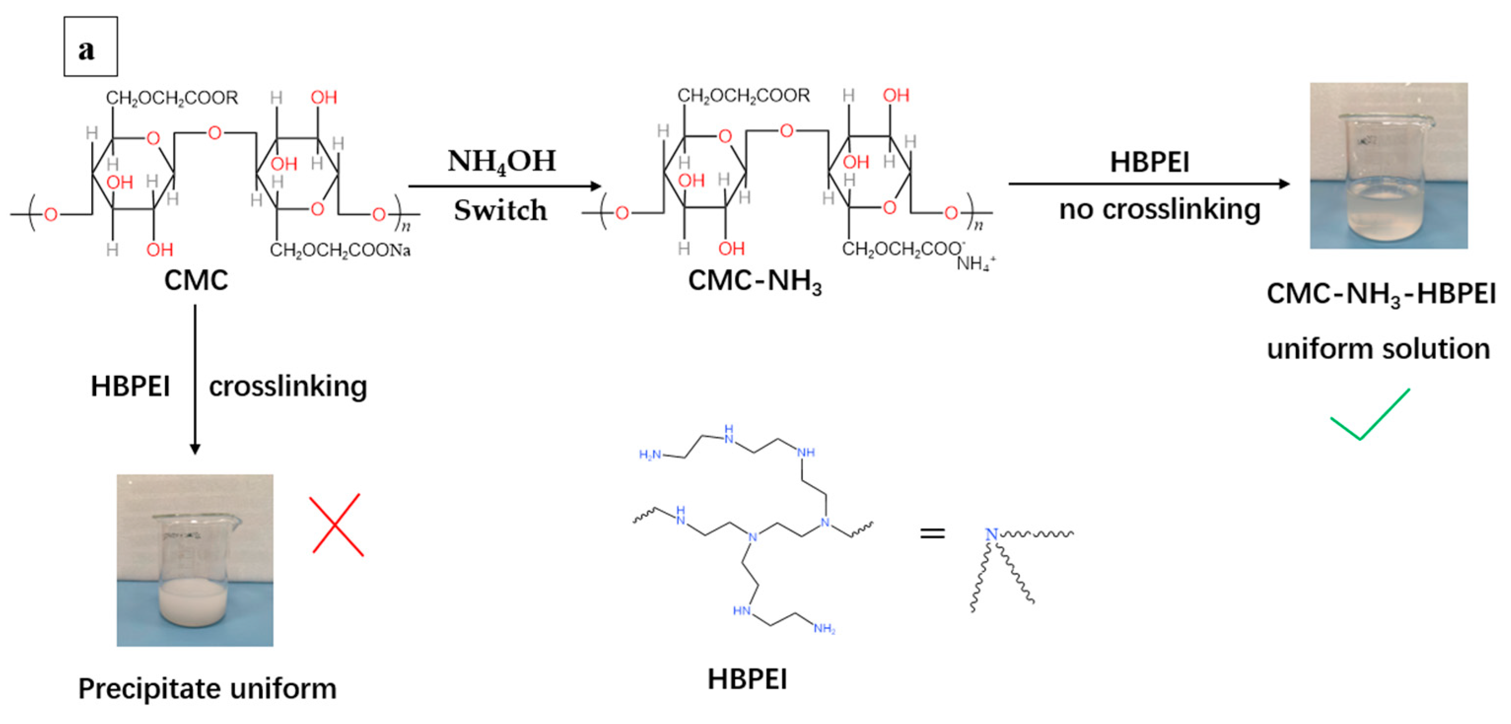
Figure 1 illustrates the synthesis of a hybrid cross-linked network binder CMC-HBPEI by “switching” and “converting” ionic bonds. While both CMC and HBPEI are soluble in water separately, they quickly form flocculent precipitates when mixed together. This indicates that CMC rapidly undergoes an acid–base neutralization reaction with HBPEI in an aqueous solution, resulting in the formation of ionic cross-linking and precipitation from the aqueous phase. However, the binder material must be maintained in a slurry state before use, so it is impossible to directly mix the CMC and HBPEI solutions for use as a binder. To solve this problem, a neutralizer, ammonia [
23], is dropped into the aqueous CMC solution to neutralize the carboxylic acid group of CMC (CMC-NH
3) before adding HBPEI. This temporarily “switches off” the ionic cross-linking reaction between CMC and HBPEI, resulting in a homogeneous binder slurry (aqueous CMC-NH
3-HBPEI solution, as shown in
Figure 1a). The addition of ammonia prevents precipitation and ensures a stable slurry state.
In the next step, the Si nanoparticles, conductive agent, and binder slurry CMC-NH
3-HBPEI are mixed and coated on the copper foil to form the Si anode (as shown in
Figure 1b). During the subsequent vacuum drying process, the volatilization of ammonia “switches on” the ionic bonding between CMC and HBPEI again, thus forming an in situ ionically cross-linked 3D network structure. It is worth noting that, in general, the interaction between polycarboxylic acid and polyamine is a reversible ionic cross-linking. However, carboxylic acids and amines start to react at 70 °C to form amides [
24]. When the temperature exceeds 90 °C, almost all ionic bonds between CMC and HBPEI are converted to covalent bonds, resulting in a covalently cross-linked network (as shown in
Figure 1c). Taking advantage of this characteristic, the ionic bonds between CMC and HBPEI are partially converted into covalent bonds by increasing the vacuum drying temperature of the anode foil, forming a hybrid cross-linked network binder CMC-HBPEI. The advantage of this hybrid cross-linking is that the covalent bonds in the network enhance the mechanical stability of the electrode structure, while the ionic bonds endow the electrode with the self-healing property that allows repeated breaking and re-forming of ionic bonds to dissipate the mechanical stresses from Si. The synergy of the two effects ensures the structural integrity of the Si anode throughout the entire charge/discharge cycle.
Ammonia not only acted as a “switch”, but also improved the flow properties of the CMC-NH
3-HBPEI solution.
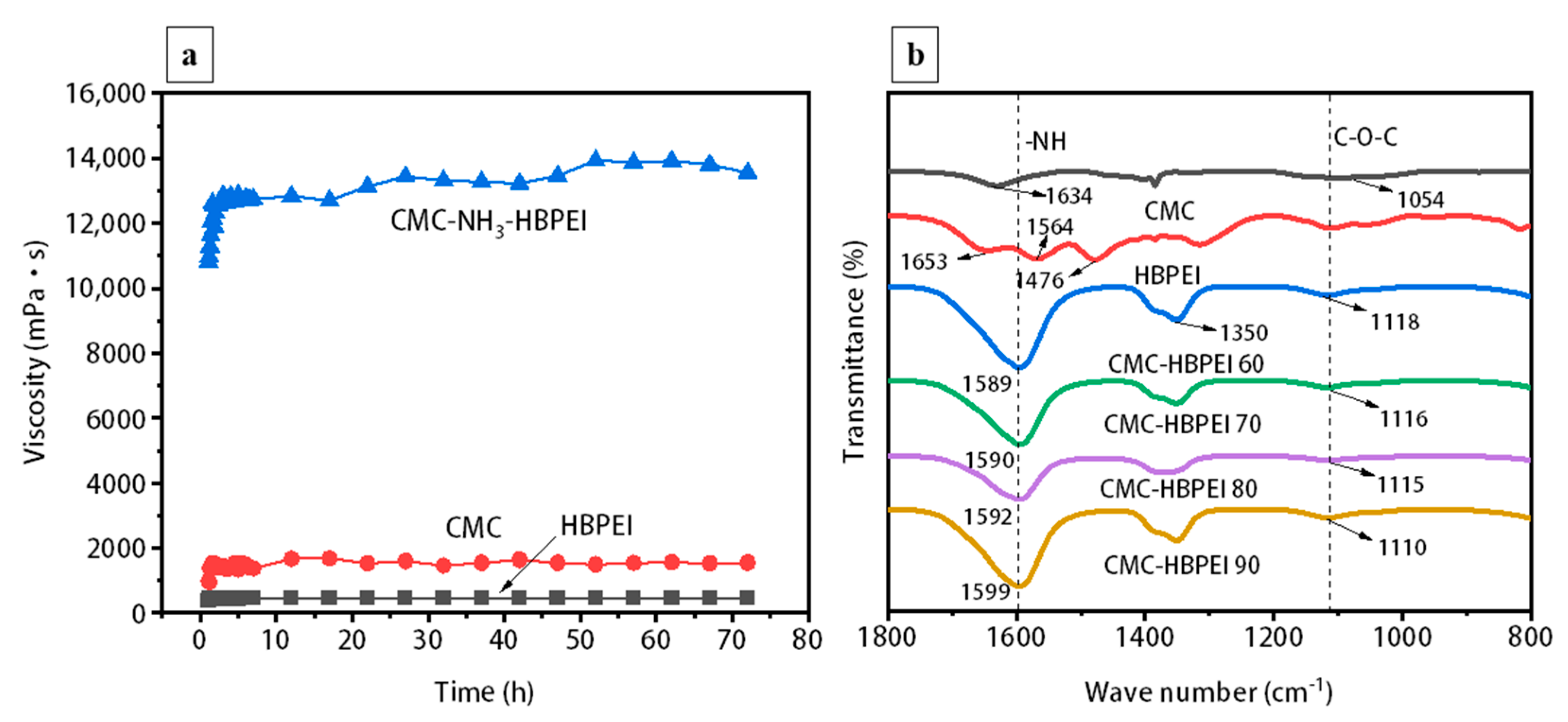
Figure 2a shows the viscosity changes of CMC, HBPEI and CMC-NH
3-HBPEI aqueous solutions over 72 h. HBPEI has the lowest viscosity in aqueous solution due to its hyperbranched structure and low molecular weight (
Figure 2a) [
21,
25]. In contrast, the linear polymer CMC presents a higher viscosity value (
Figure 2a) [
21,
26]. When ammonia and HBPEI are added to the CMC aqueous solution, The viscosity of the CMC-NH
3-HBPEI solution increased sharply and began to stabilize around 5 h. The phenomenon might be due to the presence of NH
4+ in the solution, which can neutralize the COO
− of CMC, reducing the dispersion of CMC in the aqueous solution and making it easier to form an aggregated state, thus increasing the viscosity substantially. The high viscosity of the binder solution facilitates the slowing down of precipitation and agglomeration of suspended particles, thus improving the stability of the electrode slurry [
27,
28,
29].
FTIR measurements are performed for HBPEI, CMC, and CMC-HBPEI-60, 70, 80, and 90, and the results are shown in
Figure 2b. In the HBPEI spectrum, stretching vibrations caused by N-H and -NH
2 groups appear at 1653 cm
−1, 1564 cm
−1, and 1476 cm
−1 [
13,
30]. In the CMC spectrum, the peaks of 1634 cm
−1 correspond to the characteristic absorption peaks caused by -COOH stretching vibration [
31]. According to a mass ratio of 2:8, HBPEI is added to CMC and dried at different temperatures. The absorption peaks of all CMC-HPBIE spectra shift to higher wave numbers and become broader compared to the N-H absorption peak of pure HBPEI located at 1564 cm
−1, which indicated a strong interaction formed between CMC and HBPEI during the drying process [
22]. In addition, it is observed that the C-N stretching vibration peaks around 1350 cm
−1 in all CMC-HBPEI spectra are more intense than those of CMC and HPBIE. C-O-C ester symmetric stretching vibrations are also found within 1110 to 1118 cm
−1 in all the CMC-HBPEI spectra. All these proved the successful combination of CMC and HBPEI [
32].
Furthermore, XPS is used to analyze the bonding transformation process of CMC-HBPEI during vacuum drying. As shown in
Figure 3, the N 1s spectra of all CMC-HBPEI samples can be decomposed into three separate components of HBPEI, namely tertiary, secondary and primary amine groups [
21,
32,
33]. By comparing the ratios of peak areas of primary, secondary, and tertiary amines in the CMC-HBPEI-60, 70, 80, and 90, it is found that the BE peak areas of primary amine gradually decrease with the increase in drying temperature of CMC-HBPEI, while the peak areas of secondary and tertiary amines gradually increase. This relates to the condensation reaction between CMC and HBPEI [
34]. As the drying temperature increases, the condensation reaction becomes easier. More and more amino groups of HBPEI react with carboxyl groups of CMC to form amide structures, so the hydrogen ions in the amino group of HBPEI are continuously removed, leading to a decrease in the number of primary amines and an increase in the number of tertiary and secondary amines. Eventually, tertiary amines become the major component of the amino group of HBPEI.
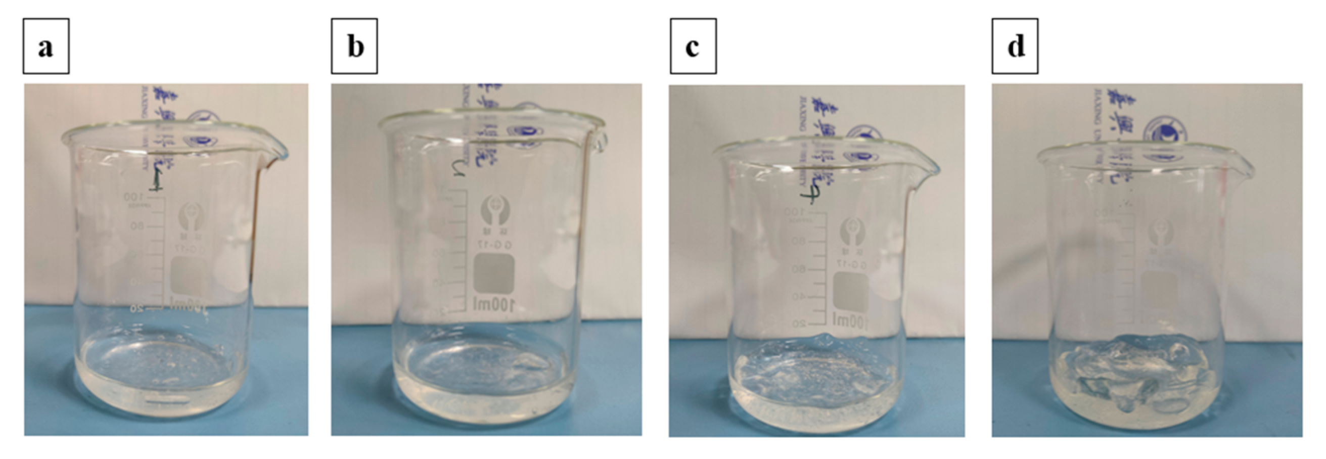
To investigate the bonding conversion between CMC and HBPEI intuitively, a dissolution test is performed. CMC-HBPEI films dried at 60, 70, 80, and 90 °C are immersed in a 1 M NaOH solution for 12 h, and their weight changes are recorded [
35,
36]. Typically, ionic bonds are disrupted in strong alkali solutions while covalent bonds remain unaffected by the acidity (pH). The CMC-HBPEI 60 film dissolved immediately after immersion, indicating that the cross-linked network primarily consists of ionic bonds at a drying temperature of 60 °C (
Figure 4a). In contrast, the CMC-HBPEI-90 film only exhibited swelling after immersion in NaOH solution (
Figure 4d). This suggests that the ionic bonds in CMC-HBPEI are completely transformed into covalent bonds after drying at 90 °C. Films dried at intermediate temperatures (70~80 °C) partially dissolved due to the presence of both types of bonds (
Figure 4b,c). These results demonstrate that increasing the drying temperature leads to a gradual conversion of ionic bonds to covalent bonds.
The ratio of covalent to ionic bonds in the CMC-HBPEI network at different drying temperatures is determined by recording the mass of the films before and after dissolution and substituting it into Equation (1) [
37,
38,
39].
Here, M1 represents the initial mass of the film sample and M2 represents the remaining mass after immersion and subsequent vacuum drying at 120 °C for 48 h. An increase in the ratio of covalent to ionic bonds in CMC-HBPEI films is observed at drying temperatures of 60, 70, 80, and 90 °C. This indicates that an increase in the conversion of ionic bonds to covalent bonds in CMC-HBPEI films occurred with increasing drying temperature, which is consistent with XPS data.
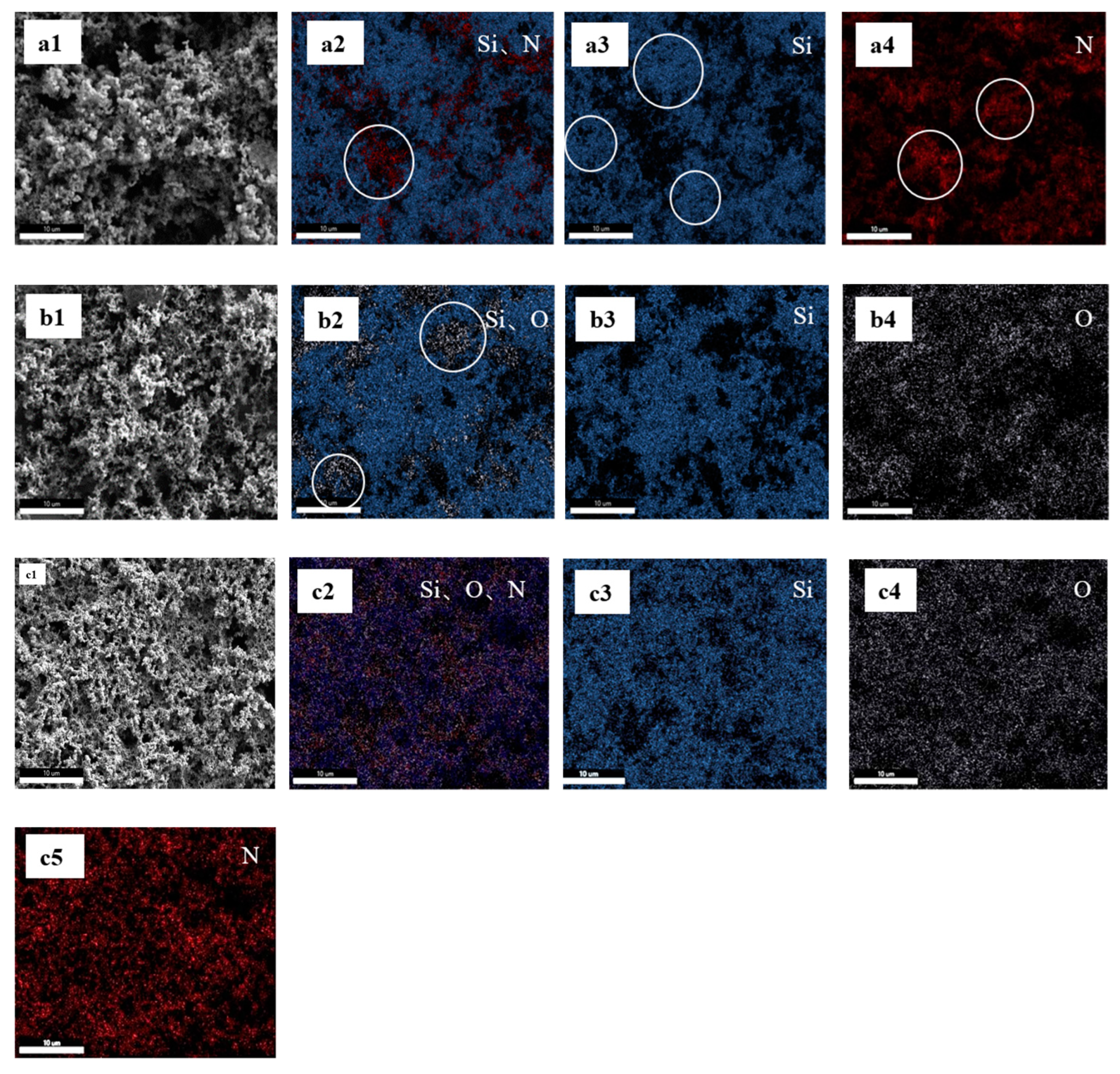
EDX has high spatial resolution and can intuitively display the distribution of Si nanoparticles and binder on the electrode surface within a millimeter range. Therefore, the combination of SEM and EDX is a suitable method for observing the surface morphology and elemental distribution of Si anodes with different binders [
21]. The SEM images show that in the Si/HBPEI anode, Si nanoparticles and HBPEI are unevenly dispersed (
Figure 5a1). In addition, the EDX spectrum reveals that the Si and N elements in HBPEI are not well overlapped (such as those circles in
Figure 5a2) and are completely separated in several regions, as indicated by the circles in
Figure 5a3,a4. This indicates that low-viscosity HBPEI tends to self-aggregate and cannot completely cover Si nanoparticles. SEM images (
Figure 5b1) indicate that there is no significant aggregation of Si or CMC when Si nanoparticles are coated on Cu foil with CMC as a binder. The EDX spectrum shows that the distribution of Si and O elements is largely overlapping (
Figure 5b2), but some areas containing only O elements can still be seen (such as those circled in
Figure 5b2). This indicates that CMC can only roughly cover Si nanoparticles rather than uniformly cover them. The FESEM image shows a uniform and dense 3D network structure for the Si/CMC-HBPEI sample (
Figure 5c1). This anode shows a more even distribution of Si, O, and N elements compared to Si/HBPEI and Si/CMC anodes (
Figure 5c2). This indicates that there are interactions such as hydrogen bonds, ion bonds and covalent bonds between CMC and HBPEI which can improve their compatibility and coverage with Si nanoparticles. Therefore, in the CMC matrix, Si nanoparticles are well dispersed and covered with HBPEI.
The adhesive between the binder and current collector is an important index for evaluating the mechanical stability of an electrode [
38,
39]. To evaluate the adhesive force, a 180° stripping test is conducted on Si/CMC-HBPEI foils.
Figure 6a shows that the adhesive force of Si/HBPEI (0.246 ± 0.019 N mm
−1) is lower than that of Si/CMC (0.309 ± 0.021 N mm
−1), which may be due to the lower dispersion and molecular weight of HBPEI, resulting in lower shear deformation resistance of Si/HBPEI films. After vacuum drying at 60 °C, an ionically cross-linked network structure is formed between CMC and HBPEI, leading to an increase in the adhesion strength of Si/CMC-HBPEI-60 foil to 0.404 ± 0.031 N mm
−1. With the increase in temperature, the ionic bonds in the CMC-HBPEI are partially transformed into covalent bonds, forming a hybrid cross-linked network structure. Therefore, the adhesive force of Si/CMC-HBPEI-70 and Si/CMC-HBPEI-80 further increases, reaching 0.496 ± 0.044 and 0.598 ± 0.036 N mm
−1, respectively. With the temperature increase to 90 ℃, most of the ionic bonds in CMC-HBPEI are converted into covalent bonds. The resulting covalent bond structure exhibits excellent mechanical properties, resulting in a maximum adhesion force of 0.712 ± 0.042 N mm
−1 for the Si/CMC-HBPEI-90 foil.
Since the tensile strength of the binder is crucial in suppressing the volume change of Si particles [
21,
40], the films of CMC, CMC-HBPEI-60, 70, 80, and 90 were subjected to tensile testing, which yielded results in line with those obtained from the 180° peel tests. Specifically, all cross-linked samples displayed higher tensile strength and Young’s modulus values compared to the pure CMC film (
Figure 6b,c). This may be due to the cross-linking resulting in a more compact network structure between the polymer chains, which improves the mechanical strength and stability of the CMC-HBPEI material. Furthermore, increasing the drying temperature leads to an increase in both the tensile stress and Young’s modulus of CMC-HBPEI films. The tensile stress and Young’s modulus of CMC-HBPEI reached the maximum values of 21.835 ± 1.636 MPa and 0.687 ± 0.056 GPa when the drying temperature reached 90 °C. This was mainly due to the gradual conversion of ionic bonds in the cross-linked network of CMC-HPBIE into covalent bonds with higher bond energy.
As a binder material for Si, it is crucial to consider the mechanical strength and the self-healing property of the binder material, which must maintain a balance between these two characteristics [
41]. Thus, to assess the self-healing capability, cross-sectional morphology of cut CMC and CMC-HBPEI-60, 70, 80, and 90 films were analyzed for morphological evolution. To facilitate observation of the self-healing phenomenon, both ends of the cut film are dyed with different colored inks and then brought into contact again without any external pressure. As shown in
Figure 7a,f, CMC film could not be reconnected after being cut, indicating that CMC itself could not form enough hydrogen bonds through a limited number of carboxyl groups to repair the damage. In contrast, all cut CMC-HBPEI films could be reconnected after contact. Among them, the reconnected membranes CMC-HBPEI-60, 70, and 80 still have a certain mechanical strength (
Figure S1). This could be attributed to the re-formation of sufficient hydrogen bonds and ionic bonds between the amino groups on the HBPEI side chains and the carboxyl groups on the CMC chains [
42,
43], which act as sutures for the cut section of the film. Among them, the CMC-HBPEI-90 film is easily pulled apart again after a successful connection (
Figure 7e,j). The possible reason is that the CMC-HBPEI-90 film is an irreversible covalent bond cross-linked network structure. When the cut CMC-HBPEI-90 film is reconnected, only a few hydrogen bonds and ionic bonds could be formed at the fracture surface [
43], so the self-healing effect is the worst.
To assess the electrochemical characteristics of Si anodes bound with CMC-HBPEI, a series of galvanostatic charge–discharge tests are performed on Li/Si half-cells [
21]. The galvanostatic curves presented in
Figure 8a illustrate the initial electrochemical performance of Si anodes with CMC, HBPEI, and CMC-HBPEI-60, 70, 80, and 90 as binders. The initial coulombic efficiencies (ICEs) of Si/CMC and Si/HBPEI were 62.11% and 57.20%, respectively. The ICEs of Si anodes using CMC-HBPEI binders are higher than those of CMC and HBPEI. The ICEs of Si/CMC-HBPEI-60, 70, 80, and 90 are 65.87%, 68.31%, 84.32%, and 75.54%, respectively. The insignificant increase in ICE value of Si/CMC-HBPEI-60 may be attributed to the inadequate mechanical stability of the ionically cross-linked network structure, which fails to withstand the stress caused by the volume expansion of Si and cannot fully encapsulate Si nanoparticles. As a result, a significant amount of electrolyte is consumed on the exposed Si surface to form a solid electrolyte interface (SEI) layer during the first cycle [
8,
9,
10]. The highest ICE value of Si/CMC-HBPEI-80 indicates that the dual cross-linked network structure coexisting with physical and chemical cross-linking can embed Si nanoparticles tightly into the matrix and completely cover them, greatly reducing the consumption of electrolytes on the Si surface [
21,
44].
To assess the cycle stability of Si anodes with various binders, half-cell charge–discharge tests are conducted for a total of 300 cycles under a current density of 500 mA g
−1. As shown in
Figure 8b, the initial specific capacity of Si/CMC decreased from 2410 to 146 mAh g
−1 after 300 cycles, while the initial specific capacity of Si/HBPEI rapidly decreased from 2468 to 180 mAh g
−1 within 20 cycles. These results suggest that neither linear nor hyperbranched structures can effectively suppress the volume expansion of Si during cycling when used alone. In the case of the CMC-HBPEI composite-binder materials, the initial specific capacity of Si/CMC-HBPEI-60 slowly decreases from 2589 to 499 mAh g
−1 after 300 cycles. Compared to Si/CMC, the improvement in the cycling stability of Si/CMC-HBPEI-60 is not significant. This is mainly due to the fact that the CMC-HBPEI network structure after 60 °C drying treatment relies solely on a simple ionic cross-linked structure, which does not provide sufficient adhesion between the binder and Si nanoparticles. Additionally, the ionic cross-linked network exhibits insufficient mechanical stability to suppress the severe volume changes of Si nanoparticles. This indicates that the mechanical stability is inadequate to curb the Si’s volume expansion, and the self-healing properties are ineffective. When the drying temperature of the Si anode rises to 90 °C, the cycling curve shows two stages. In the initial 53 cycles, the specific capacity of the Si/CMC-HBPEI-90 decreases slowly, and then the decrease rate gradually accelerates afterward. After 300 cycles, the initial specific capacity of Si/CMC-HBPEI 90 decreases from 2720 mAh g
−1 to 762 mAh g
−1. The supposed reason for this is that most of the ionic bonds in the binder network convert to covalent bonds after 90 °C vacuum drying. A covalently cross-linked network is effective in suppressing the initial cycle volume expansion of Si. However, as the number of cycles increases, the covalent bonds gradually break and fail to form new covalent bonds, resulting in the failure of the volume suppression effect of the 3D network at later cycling [
45]. Out of all the tested samples, Si/CMC-HBPEI-80 exhibits the most favorable cycling performance, maintaining a specific capacity of 1545 mAh g
−1 even after 300 cycles (as shown in
Figure 8b). The cycling stabilities of Si anodes using water-soluble polymers (polyacrylic acid (PAA) [
46], polyvinyl alcohol (PVA) [
47]), natural polymers (chitosan (CS) [
48], sodium alginate (Alg) [
49], lignin [
50], carrageenan [
51]), or synthetic self-healing polymers (SHP) [
52] as binders are summarized in
Table S1. Compared with these binder materials, the hybrid cross-linked network binder CMC-HBPEI not only has moderately high cycling stability, but also has the characteristics of a green and simple preparation process. A possible reason is that at a drying temperature of 80 °C, both ionic and covalent bonds coexist in the network of the binder. The covalently cross-linked network ensures the stability of the anode structure, while the reversible ionically cross-linked network repeatedly dissipates the mechanical stress generated from the lithiation expansion of Si through bond breaking and reconstruction and repairs the damages to the network structure. The synergy of covalent and ionic bonds enables the hybrid network binder material to suppress the volume expansion of Si [
53] continuously.
Figure 8c depicts the variation of the specific capacity of half-cells at current densities ranging from 200 to 2000 mA g
−1, enabling an assessment of the impact of CMC-HBPEI binders on the rate capacity of Si anodes. At a current density of 200 mA g
−1, the specific capacity of the Si/HBPEI anode rapidly decreased from 2330 to 401 mAh g
−1 within the first 10 cycles. Meanwhile, the specific capacities of the other anodes gradually decreased as the current density increased. At 2000 mA g
−1, the specific capacities of the Si/CMC, Si/CMC-HBPEI-60, 70, and 90 anodes dropped to 355, 1034, 1470, and 1601 mAh g
−1, respectively. Upon returning the current density to 400 mA g
−1, the specific capacities of Si/CMC-HBPEI-60, 70, and 90 recovered to 509, 1090, and 901 mAh g
−1, respectively. Unlike other anodes, Si/CMC-HBPEI 80 maintains a specific capacity of 1423 mAh g
−1 even at a current density of 2000 mA g
−1. Upon restoring the current density to 400 mA g
−1, the specific capacity of Si/CMC-HBPEI 80 increases to 1597 mAh g
−1. The superior rate performance of Si/CMC-HBPEI-80 could be attributed to the stable hybrid network structure and the ionic conductivity of the HBPEI branched chains, which facilitate the rapid diffusion of lithium ions to the Si surface [
54].
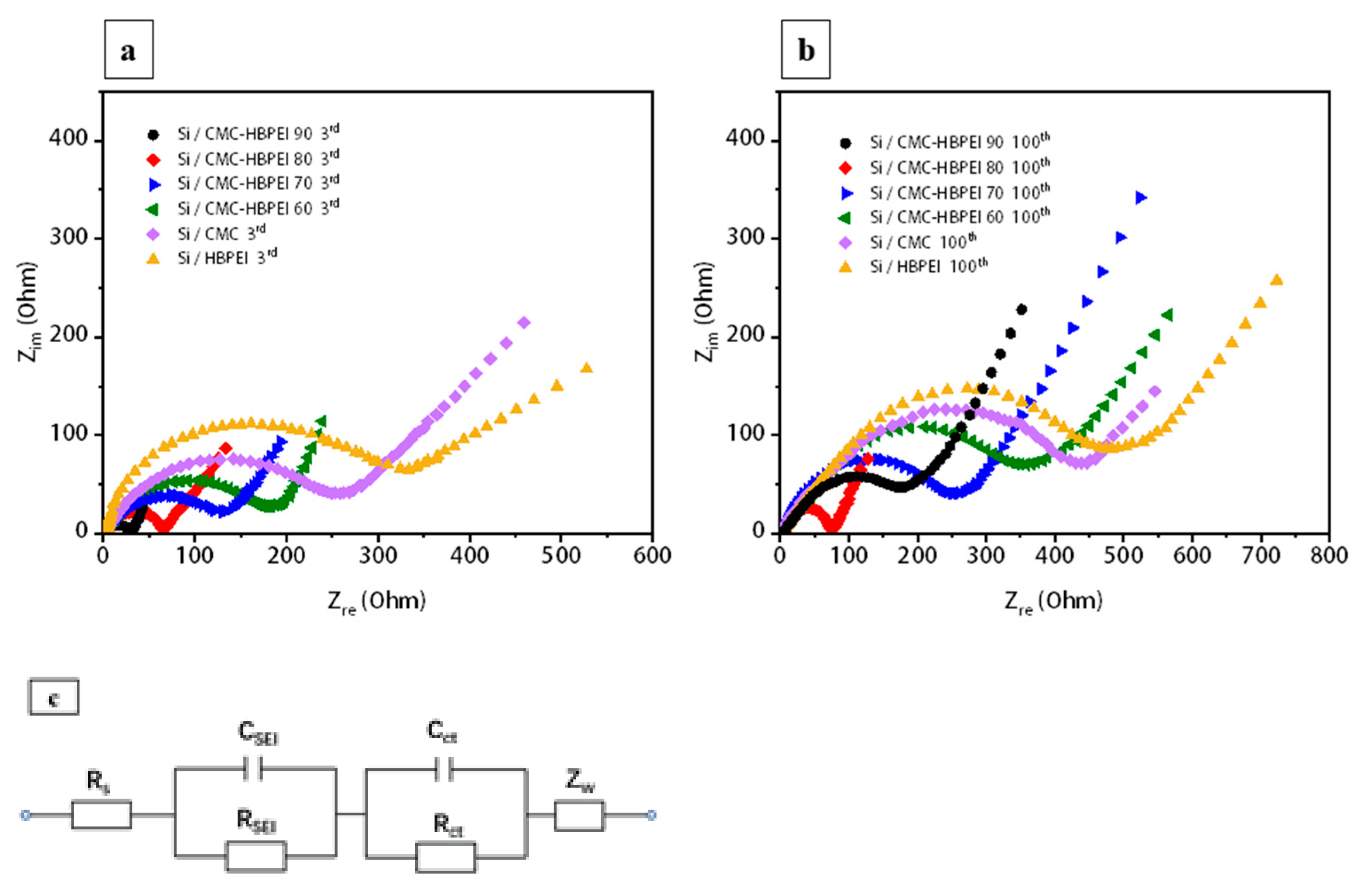
To assess the structural stability of Si anodes with different binders after cycling, the EIS testing is conducted to examine the impedance changes of the anodes. The Nyquist plots of all anodes after 3 and 100 cycles show a semicircle overlapped by a high-frequency semicircle (HFS) and a low-intermediate-frequency semicircle (MHS), and a long low-frequency line (LFL), which represent R
SEI, R
ct, and W, respectively. The corresponding equivalent circuit is also drawn in
Figure 9c (R
s represents electrolyte resistance) [
21,
55]. The fitting values of R
SEI and R
ct are obtained and listed in
Table 1, and the ionic diffusion coefficients (D) are calculated from the slope of the straight line between Z
re and ω
−1/2 according to Equations (2) and (3) [
34].
The symbols R, T, and F represent the gas constant, absolute temperature, and Faraday’s constant, respectively, while A represents the electrode surface area and C is the molar concentration of Li ions [
56]. As shown in
Table 2, the R
SEI values increase, and the D values decrease after 100 cycles. Si/CMC-HBPEI 90 shows the lowest RSEI and the highest D among all the anodes after 3 cycles. However, Si/CMC-HBPEI-80 maintains the lowest RSEI and the highest D after 100 cycles. These phenomena suggest that although the stability of the binder material owing hybrid cross-linked network was slightly inferior to that of the binder material endowing the covalent network in the initial cycles, the reversible ionic bonds in the hybrid cross-linked network could continuously alleviate the volume expansion of Si, thus reducing the interfacial resistance for extended cycle life.
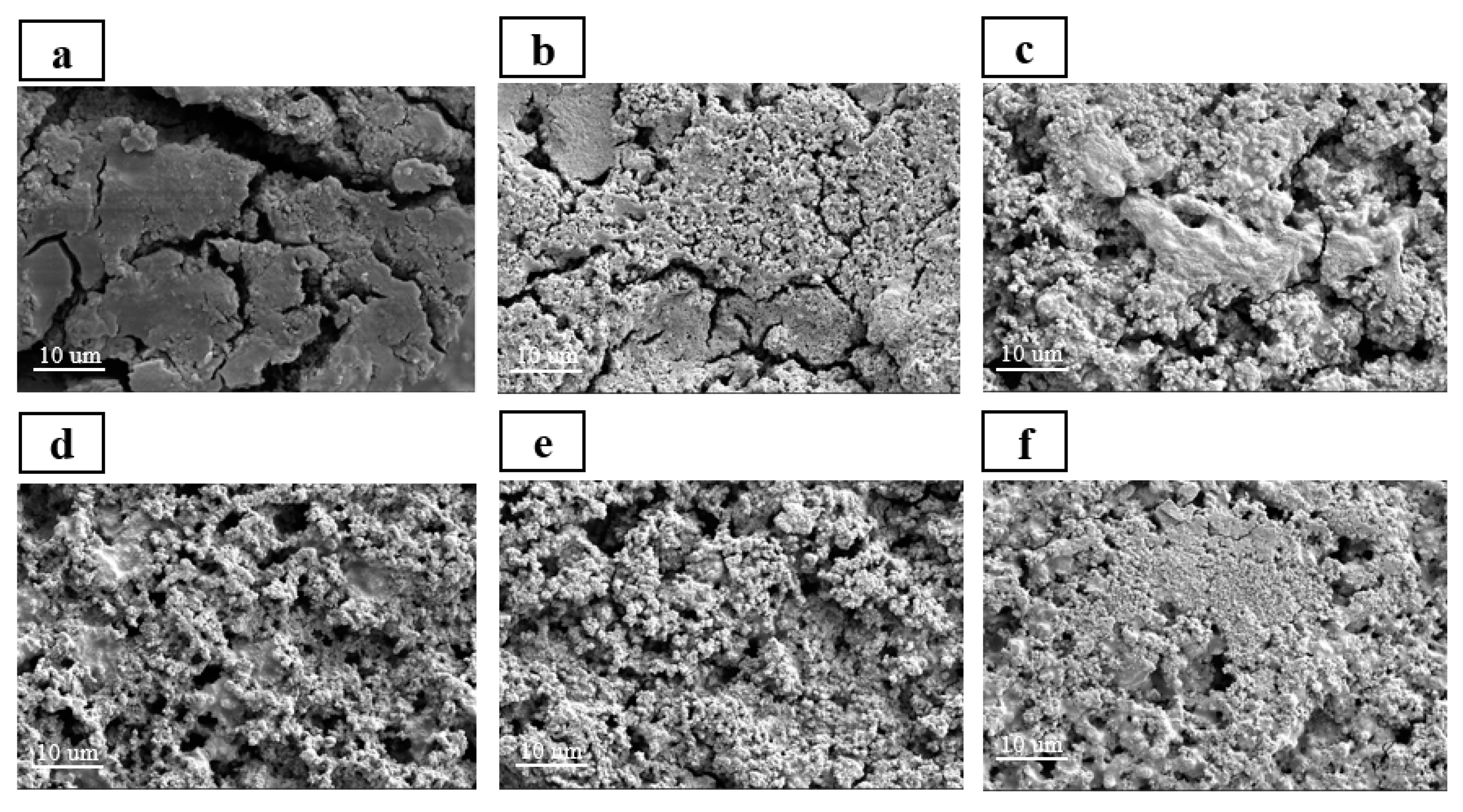
FESEM and EDS are used to observe the morphological changes and SEI layer formation of Si anodes with different binders before and after 100 cycles. The EDS mapping images confirmed that after 100 cycles, all electrodes were covered with SEI layer (
Figure S2). Compared to the surface morphologies before the cycling (
Figure S3), significant differences were observed in the surface morphology of Si/HBPEI, Si/CMC, Si/CMC-HBPEI-60, and 90 anodes after 100 cycles, characterized by the presence of deep and wide cracks and thick SEI layers formed on the surface (
Figure 10a–c,f). In contrast, Si/CMC-HBPEI-70 and 80 anodes displayed no apparent cracks or morphological changes on the surface before (
Figure S3d,e) and after 100 cycles (
Figure 10d,e). Notably, the original network structure morphology remained recognizable on the surface of Si/CMC-HBPEI-80 (
Figure 10e), indicating that Si/CMC-HBPEI-80 presents the best stability and structural integrity after 100 cycles. This is because the Si/CMC-HBPEI-80 electrode adopts a hybrid cross-linked network structure formed by ionic and covalent bonds, which exhibits strong mechanical properties and bonding reversibility, effectively suppressing the volume expansion of Si nanoparticles and repairing the structural breakage of the electrode, thus mitigating the capacity decay of the Si anode.
