Article

Hollow CuSbSy Coated by Nitrogen-Doped Carbon as Anode Electrode for High-Performance Potassium-Ion Storage

1
Institute of Nano Chemistry and Nanobiology, School of Environmental and Chemical Engineering, Shanghai University, Shanghai 200444, China
2
Fachgebiet Angewandte Nanophysik, Institut für Physik & IMN MacroNano, Technische Universität Ilmenau, 98693 Ilmenau, Germany
*
Author to whom correspondence should be addressed.
These authors contributed equally to this work.
Batteries 2023, 9(5), 238; https://doi.org/10.3390/batteries9050238
Submission received: 15 March 2023 / Revised: 19 April 2023 / Accepted: 21 April 2023 / Published: 23 April 2023

Abstract

:
As a potential anode material for potassium-ion batteries (PIBs), bimetallic sulfides are favored by researchers for their high specific capacity, low cost, and long cycle life. However, the non-ideal diffusion rate and poor cycle stability pose significant challenges in practical applications. In this work, bimetallic sulfide CuSbSy@C with a yolk-shell structure was synthesized by in situ precipitation and carbonization. When CuSbSy is applied in the anode of PIBs, it can provide the desired capacity and reduce the volume expansion of the compound through the synergistic effect between copper and antimony. At the same time, the existence of the nitrogen-doped carbon shell confines the material within the shell while improving its electrical conductivity, inhibiting its volume expansion and aggregation. Therefore, CuSbSy@C exhibits a satisfactory capacity (438.8 mAh g−1 at 100 mA g−1 after 60 cycles) and an excellent long cycle life (174.5 mAh g−1 at 1000 mA g−1 after 1000 cycles).

1. Introduction

Because the typical reduction potential of potassium (−2.93 V) is comparable to the reduction potential of lithium (−3.04 V), potassium ion batteries (PIBs) are drawing more attention as a useful alternative to lithium-ion batteries (LIBs) [1]. In addition, massive energy storage systems can be equipped with enough potassium thanks to the abundance of resources that are kept in the earth’s crust. [2,3]. Despite these mentioned advantages, there are still several challenges to impede the practical applications of PIBs. For instance, the slow kinetic process of potassium ions (K+) during charging/discharging and the poor rate performance are caused by the large ionic radius of K+ (1.38 Å) [4,5,6]. Besides, undesirable expansion of the material and K+ due to the reaction, known as the intercalation of K+ or alloying with K+, causes the destruction of the active material structure and an irreversible decrease of capacity [7,8,9]. Therefore, developing various anode materials with high capacity, high stability, and facilitated K+ kinetic for PIBs effectively pushes the further development of PIBs.
Anode materials research reveals promising storage systems for PIBs, such as carbon-based materials [10,11], organic materials [12,13], metallic oxides [14,15], metallic sulfides [16,17], metallic selenides [18,19], metallic phosphides [20,21], etc. Among them, carbon-based materials could be more practical and convenient since they are easily accessible from nature. However, they deliver a lower reversible capacity. Organic materials with tunable chemical composition have expanded their applications as anode/cathode electrode materials. But they are usually limited by poor electronic conductivity [10,12]. Metal sulfides with tantalizing capacities can promote the electrochemical performance of PIBs, Nevertheless, the bulk dilatation of these metallic sulfides and the limited cycle life of these electrodes would adversely affect their practical applications [22,23,24]. Therefore, much attention has been focused on pursuing effective strategies to realize the high performance of PIBs by nanostructure engineering, compositing with conductive materials [25], and heteroatoms doping in metal sulfides [26]. These strategies dramatically enhance the capacity and stability of the materials and provide more opportunities for the commercial application of bimetallic compounds in PIBs. For instance, Huang et al. embedded Cu9S5 into a porous carbon framework derivatized from Zn-based MOF by vulcanization and subsequent ion exchange [27]. Cu9S5 anode exhibited a reversible capacity of 316 mA h g−1 after 200 cycles at 100 mA g−1 and a better rate performance of 170 mAh g−1 at 2.0 A g−1. Wang et al. obtained Bi2S3@SC by coating sulfur-doped carbon on the surface of Bi2S3 [28]. Bi2S3@SC anode achieved high reversible capacity and superior rate capacity. These strategies are effective in mitigating the bulk changes of electrode materials, but the rate and cycle performance at a high current density of the monometallic sulfides has been limited to a certain extent. Therefore, we focus on bimetallic sulfides with synergistic effects that have higher capacity and stability than monometallic sulfides. Structural integrity and cyclic stability are maintained by reducing volume expansion and pulverization of the material. Since the redox potentials of the two metals are different, bimetallic sulfides take full advantage of their differences in electrochemical reactions and exhibit higher electrochemical performance. So far, some bimetallic sulfides have made some research progress in PIBs [29,30,31,32,33]. The reduced graphene oxide encapsulated flower-like spherical FeCoS2 obtained by Chen et al. was used as the anode for PIBs, it was capable of maintaining a reversible capacity of 365.2 mAh g−1 at 100 mA g−1 after 150 cycles [16]. The CoS2/ZnS@rGO prepared by Sikandar Iqbal et al. exhibited excellent cycling performance, maintaining a high reversible capacity of 565 mAh g−1 after 100 cycles at 100 mA g−1 [17]. These studies show that bimetallic sulfides can achieve higher capacities in PIBs, but they are generally costly because of the expensive graphene used. Additionally, the electrode materials have shown average rate performance at high current densities. So far, there are still limitations in the study of bimetallic sulfides, and further investigation is needed.
Therefore, in this work, the synthesis of yolk-shell structured CuSbSy@C nanocomposites via in-situ precipitation and carbonization is simple and the precursor materials are cheap. The intrinsic properties of CuSbSy delivered high capacity, benefiting from the appealing electrochemical conversion and alloying mechanisms. The nitrogen-doped carbon shell is considered a buffer layer to limit the bulk expansion of CuSbSy nanoparticles to a limited space while avoiding the aggregation of nanoparticles, and in addition, it provides more defects and active sites to store more K+ during the cycling process. At the same time, the existence of a carbon shell also increased the electroconductivity of CuSbSy material. Thus, CuSbSy@C exhibited excellent reversible capacity (438.8 mA h g−1 at 100 mA g−1 after 60 cycles) and long cycle life (174.5 mA h g−1 at 1000 mA g−1 after 1000 cycles) in PIBs.

2. Materials and Methods

2.1. Materials

Sodium citrate (C6H5Na3O7, ≥99.5%), copper sulfate pentahydrate (CuSO4·5H2O, ACS reagent grade, ≥99%), antimony chloride (SbCl3, ≥99.95%), sodium hydroxide (NaOH), L-ascorbic acid, sodium sulfide nonahydrate (Na2S·9H2O, ≥99.5%), muriatic acid (HCl, 37%), tris (hydroxymethyl) aminomethane (Tris), thioacetamide (TAA), dopamine hydrochloride (PDA), potassium metal (K, chunks in mineral oil, 98%) was purchased from China National Medicines Corporation Ltd., (Beijing, China) potassium bis (fluorosulfonyl) imide (KFSI, 97%), ethylene carbonate (EC, 99%), and diethyl carbonate (DEC, 99%) was purchased from Sigma-Aldrich (St. Louis, MO, USA).

2.2. Synthesis of Cu9S5 and Sb2S3

First, 6 mmol of CuSO4·5H2O and 2 mmol of C6H5Na3O7 were mixed into 100 mL of distilled water and stirred for 30 min at a constant speed to form clarified solution A. A total of 0.1 mol NaOH was dispersed in 80 mL distilled water and the clarified solution B was achieved by magnetic stirring for 15 min. Slowly drop solution B into solution A under magnetic stirring. Next, 6 mmol of L-ascorbic acid was poured into the solution. After stirring for some time, the mixture was centrifuged to obtain Cu2O. Then, the resulting Cu2O was supersonically distributed in 100 mL distilled water for 30 min to form solution C. To make solution D, 24 mmol Na2S·9H2O was poured into 40 mL of distilled water. After pouring solution D into the burette, adding solution C in a uniform drop, and stirring for 1 h, the centrifuged solid was scattered in 100 mL of 2 M hydrochloric acid to wash out the superfluous Cu2O. The obtained sediment was cleaned by centrifugation to a pH-neutral supernatant and dried for 12 h to yield Cu2S. To acquire Sb2S3, 0.5 mmol of SbCl3 was distributed in 40 mL of ethylene glycol and agitated for 4 h, subsequently, adding 2 mmol TAA and stirring for 5 min. The mixture was hydrothermally treated in a reaction vessel at 160 °C for 12 h and then centrifuged and dried at 60 °C. In a tube furnace, Sb2S3 was heated to 400 °C at an annealing temperature of 3 °C/min and then held for 2 h.

2.3. Synthesis of Cu2S@C, Sb2S3@C

Firstly, 700 mg Cu2S was ultrasonically distributed in 150 mL tris buffer (1 M) for 30 min. To the mixture, 700 mg of dopamine hydrochloride was added and stirred continuously for 24 h. The resulting mixture was washed with deionized water to neutrality and then washed by centrifugation with anhydrous ethanol. Cu2S@PDA was acquired by vacuum stoving the precipitate at 60 °C. Then, 1 g Cu2S@PDA was put in a tubular furnace, warming to 450 °C under the protection of the Ar atmosphere, and kept for 3 h. The Cu2S@C composite was removed after natural cooling. Sb2S3@C was produced using the same method as Cu2S@C except that Cu2S was replaced by Sb2S3.

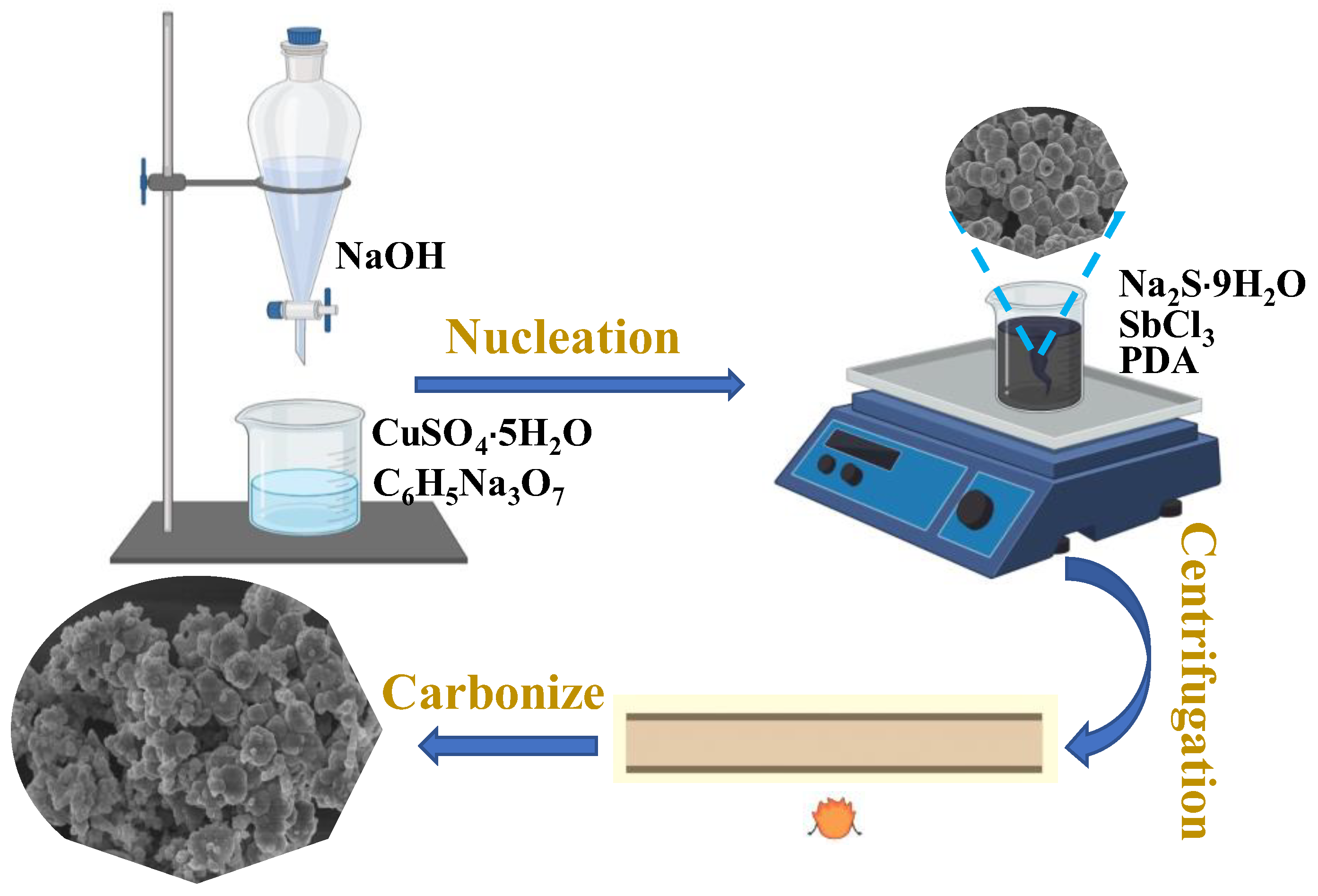
2.4. Synthesis of CuSbSy@C and CuSbSy

Firstly, 500 mg of Cu2S@C composite material was dissolved in 100 mL of anhydrous ethanol, and solution E was formed after 30 min of ultrasonic dispersion. Addition of 7 mmol of antimony trichloride (SbCl3) to 100 mL of anhydrous ethanol to fully dissolve, and after complete dissolution, solution F was formed. Solution F was slowly dripped into solution E under magnetic stirring, and after adding all drops, the solution was mixed with magnetic stirring for 24 h. CuSbSy@C was obtained by centrifugally cleaning the obtained black sediment with anhydrous ethanol and drying it for 12 h at 60 °C. A total of 500 mg CuSbSy@C was held at 450 °C for 1 h with a temperature rise rate of 3 °C/min to improve crystallinity. The synthesis process of CuSbSy was the same as that of CuSbSy@C except that no carbon was added.

3. Results and Discussion

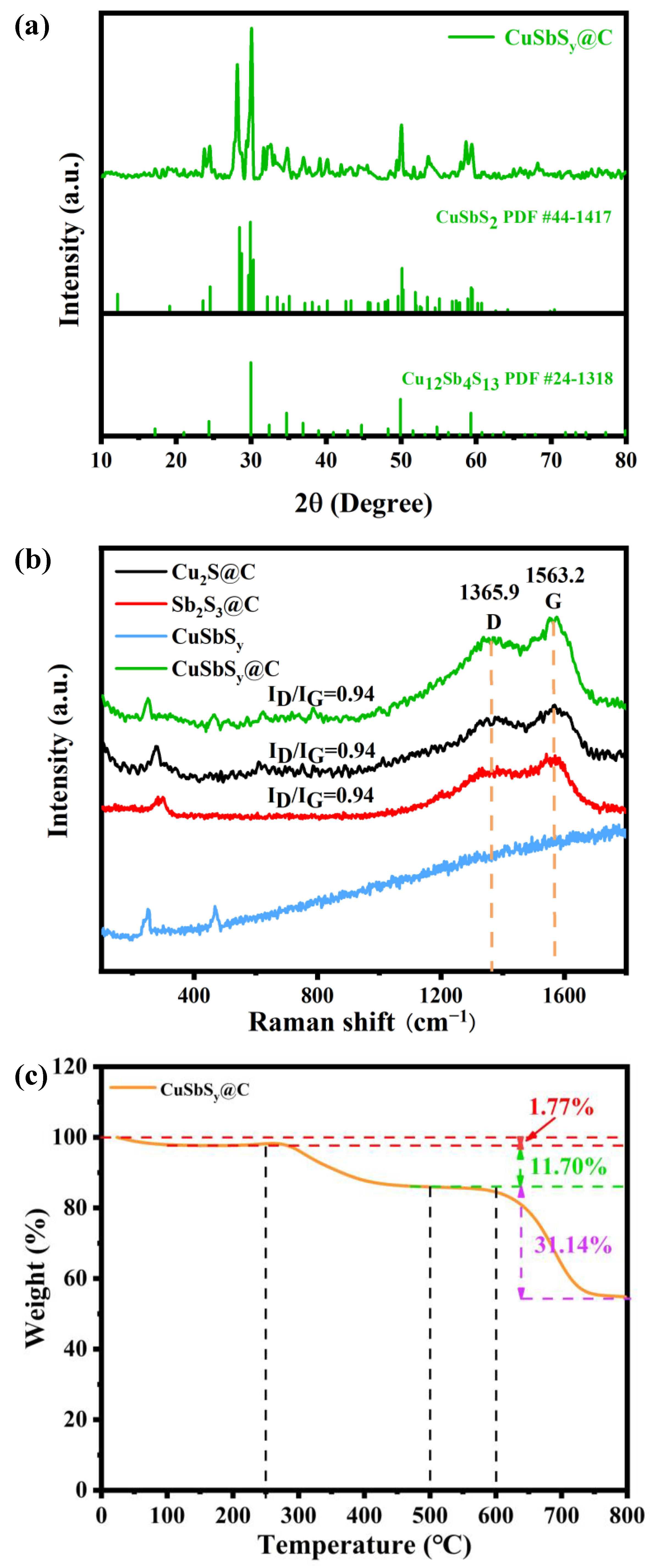
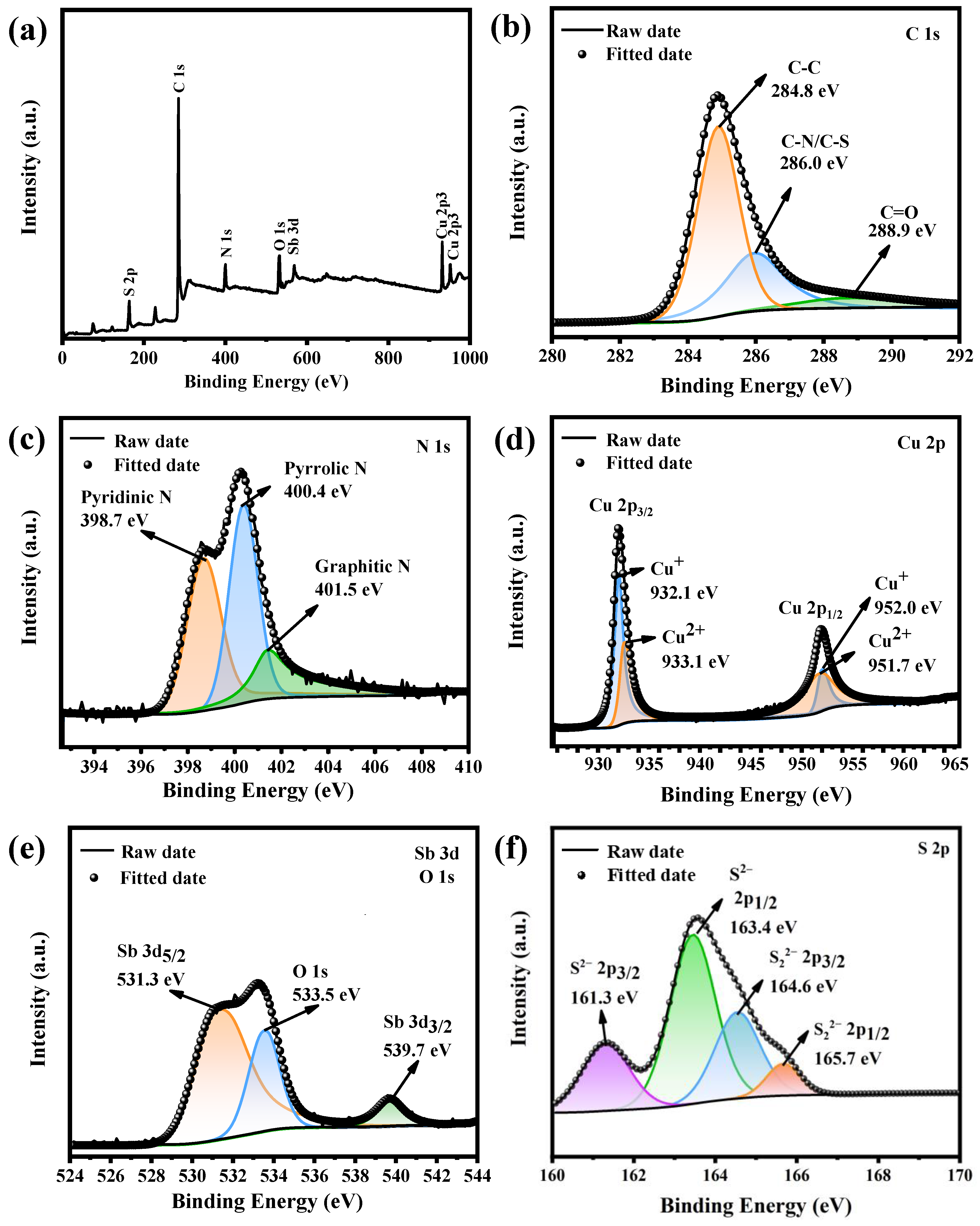
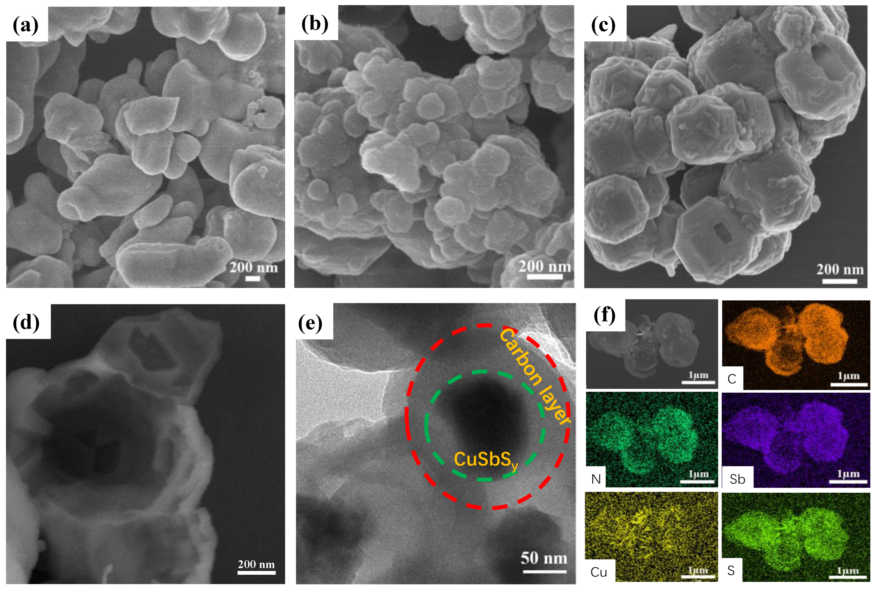
3.1. Material Characterization

Figure 1 depicts the schematic method for the synthesis of the yolk-shell structure CuSbSy@C. First of all, CuSO4·5H2O and C6H5Na3O7 were dissolved in deionized water, and Cu(OH)2 precipitate was formed after adding NaOH, and then L-ascorbic acid was added to form Cu2O red precipitate. Then, Na2S·9H2O was added and the excess Cu2O was washed away with HCl to obtain Cu2S, which was subsequently coated with dopamine and carbonized to obtain Cu2S@C. Finally, SbCl3 was added and carbonized again to form the CuSbSy@C composite with a yolk-shell structure.
As shown in Figure 2a, the morphology of Cu2S@C presented irregular and unevenly distributed nanoparticles. The Sb2S3@C consisted of a large number of stacked nanoparticles with a diameter of approximately 180 nm (Figure 2b). Clearly, the CuSbSy hollow nanoparticle has a uniform shell and a wall thickness of around 50 nm (Figure 2c). As seen in Figure 2d–f, the CuSbSy@C exhibited a homogeneous micro-spherical yolk-shell structure after carbon coating and annealing. The acquisition of this unique yolk-shell structure may be due to the volume of the internal metallic material first expanding the carbon layer after the expansion during the ion exchange reaction, and the internal material shrinkage during annealing, leading to the formation of large voids between the spherical shell and the internal nano microspheres. This unique structure improved the stability of the material compared to Cu2S@C, Sb2S3@C, and CuSbSy and effectively avoided agglomeration and escape of active substances. The presence of a yolk-shell structure obtained more uniform void distribution, more electrochemically active sites, larger nanomaterial/electrolyte contact area, shorter ion diffusion paths, accelerated ion transport, and adapted to volume changes during potassiation [34,35,36]. Figure 2e shows the transmission electron microscope (TEM) images of CuSbSy@C. The part surrounded by the green circle was the pure material of CuSbSy, and the position of the carbon layer is in the middle of the red and green lines. To confirm the precise morphology and distribution of the components of the substance, selecting elemental mapping (EDS) tests were performed on the active material in a defined area. The Cu, Sb, S, C, and N elemental distributions can be seen visually by EDS (Figure 2f). In addition, the homogeneous dispersion of carbon and nitrogen characteristics was seen, which also demonstrated that the surface of CuSbSy was covered by a uniform layer of nitrogen-doped carbon.
X-ray diffraction (XRD) and Raman were used to characterize Cu2S@C, Sb2S3@C, CuSbSy, and CuSbSy@C. Figure 3a shows the XRD spectra of CuSbSy@C in agreement with the standard card (Cu12Sb4S13 # PDF 24-1318, CuSbS2 # PDF 44-1417). The XRD patterns of Cu2S @ C, Sb2S3@C, and CuSbSy also corresponded to the standard cards (Figure S1). The peaks corresponding to the elements in CuSbSy@C were found on the diffraction planes (013), (110), (111), (410), (020), and (301), which was confirmed the successful preparation of CuSbSy@C [33,37,38,39]. To obtain the content of Cu, Sb, and S elements in the compound more precisely, the compound was tested by Inductively coupled plasma-Mass Spectrometry (ICP-MS), and the results showed that the ratio of the three elements in the compound was 1:1.63:0.62 (Table S1). The compound was named CuSbSy@C in the text. As for Raman spectra of Cu2S@C, an obvious characteristic peak of Cu2S appears at 290 cm−1, while the weak peak at 610 cm−1 could be attributed to the signal of CuO due to the oxidation of the material exposed to the air [40]. From the Raman spectra of Sb2S3@C, we can see that there are two continuous characteristic peaks at 284 and 311 cm−1, corresponding to the vibration of the Sb-S bond [41]. The characteristic peak at 250 cm−1 could be ascribed to the vibration of the Cu-S bond in the sample of CuSbSy and CuSbSy@C, while the characteristic peak at 468 cm−1 is due to the characteristic phonon vibration of chalcopyrite CuSbS2 phase [42]. The weak peaks at 624 and 785 cm−1 may be related to the oxidation of CuSbS2 to form oxides when exposed to air (Figure 3b). In addition, strong peaks of Cu2S@C, Sb2S3@C, and CuSbSy@C in the Raman spectra appear at 1563.2 and 1365.9 cm−1, correlating to the G-band of graphitic carbon and the D-band of amorphous carbon, respectively. The proportion of the two peaks was determined as the strength ratio (ID/IG) of the material, and the ratio was 0.94, which was less than 1.0, indicating that there were many defects in the carbon in the composites [16,43]. According to the existing research, materials with a lot of defects largely provided sufficient K+ storage sites and showed excellent electrochemical performance in the application of PIBs [44,45]. To further characterize the carbon content of the material, the samples were subjected to thermogravimetric analysis (TGA) at temperatures ranging from 25 to 800 °C. As shown in Figure 3c, the evaporation of residual moisture in the material caused a small mass loss (1.77%) of CuSbSy@C in the temperature range of 25–250 °C. The slow mass loss (11.7%) of CuSbSy@C at 250–500 °C would be explained in two ways. On one hand, the carbon in CuSbSy@C was burned completely, resulting in mass loss. On the other hand, the quality was improved by forming oxides (CuO and Sb2O3). As a result, the overall capacity loss was relatively slow. The loss of mass was highest at about 750 °C when the oxide was completely decomposed, and the mass loss reached 31.14% tremendously. According to the mass loss in each temperature range, the carbon content of CuSbSy@C was 31.3–34.5%, and its low carbon content makes the compound maintain high capacity under the basis of stability.
The chemical composition of CuSbSy@C was further determined by X-ray Photoelectron Spectroscopy (XPS) analysis. The real presence of Cu, Sb, S, C, N, and O elements in CuSbSy@C composites was confirmed by XPS spectra in the 0–1000 eV binding energy range (Figure 4a). Figure 4b–f presents the fine spectrum of the different elemental orbitals in CuSbSy@C. Figure 4b shows the fine spectrum of C 1s with C=O, C-N/C-S, and C=C bonds belonging to the peaks at 288.9 eV, 286.0 eV, and 284.8 eV, respectively [46]. Among them, the presence of C-S bonds indicated that the sample had been doped with some S atoms in addition to binding to the metal, whereas the appearance of C=O bonds was possibly caused by the sample being exposed to air. From the N 1s fine spectrum of the material, characteristic peaks were found at 398.7 eV, 400.4 eV, and 401.5 eV, corresponding to pyridine nitrogen (38.91%), pyrrole nitrogen (40.8%), and graphitized nitrogen (20.29%), respectively (Figure 4c) [27]. Four characteristic peaks appeared in the 2p orbitals (2p3/2 and 2p1/2) of Cu. Cu+ had two characteristic peaks at 932.1 eV and 952.0 eV, while Cu2+ had two peaks at 933.1 eV and 951.7 eV. (Figure 4d). The simultaneous presence of copper elements in two valence states (Cu+ and Cu2+) in CuSbSy@C had been demonstrated. A pair of characteristic peaks belonging to Sb 3d5/2 and Sb 3d3/2 were observed in the XPS spectra of Sb 3d at 531.3 eV and 539.7 eV [37,38]. Additionally, surface oxidation from air exposure produced an O 1s peak at 533.5 eV (Figure 4e). The XPS spectrum of S 2p in Figure 4f shows two pairs of peaks, one at 165.7 eV and 164.6 eV, and the other at 163.4 eV and 161.3 eV corresponding to the spin orbitals of S 2p3/2 and S 2p1/2 for (S22−) and (S2−), respectively [47].

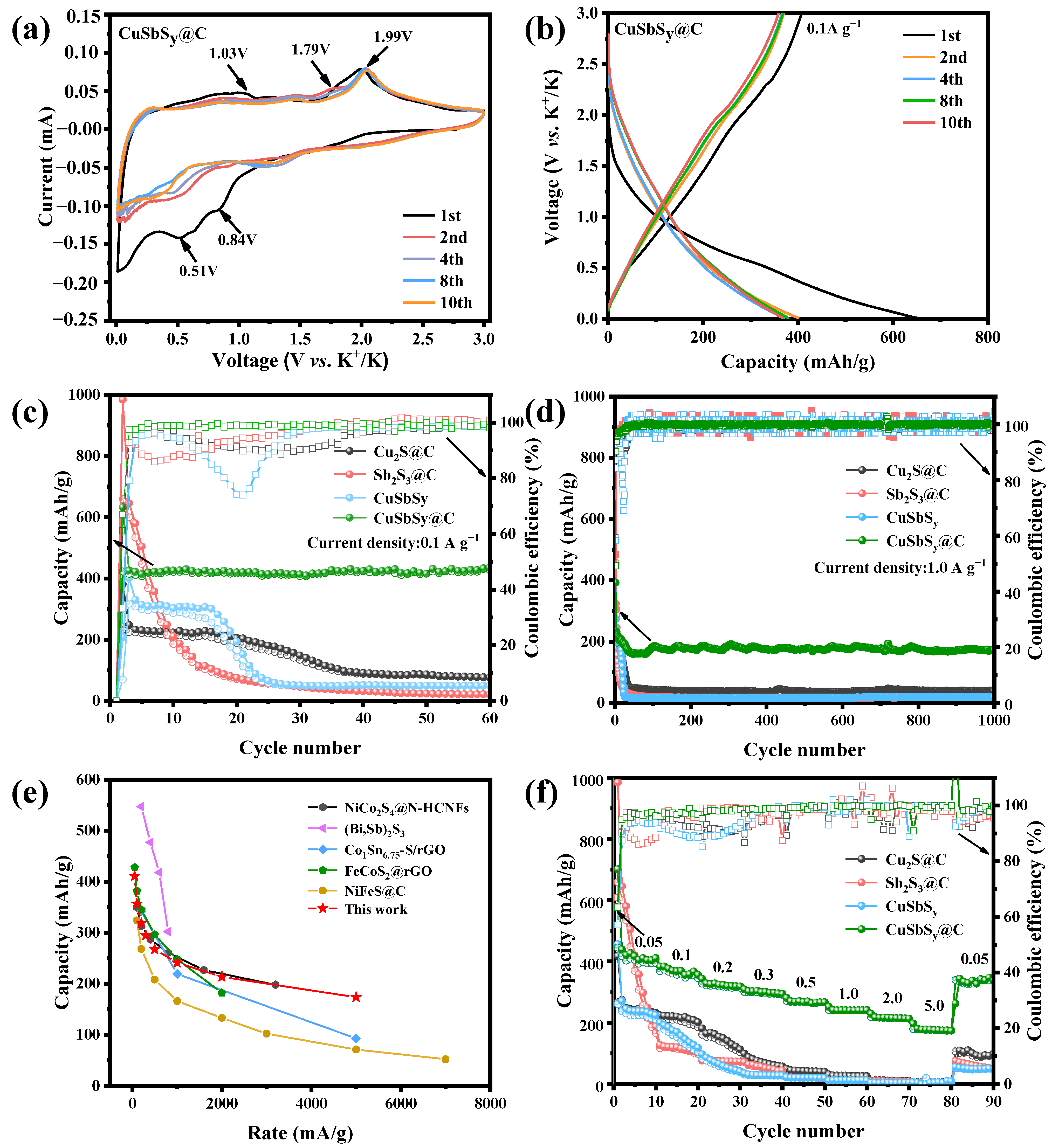
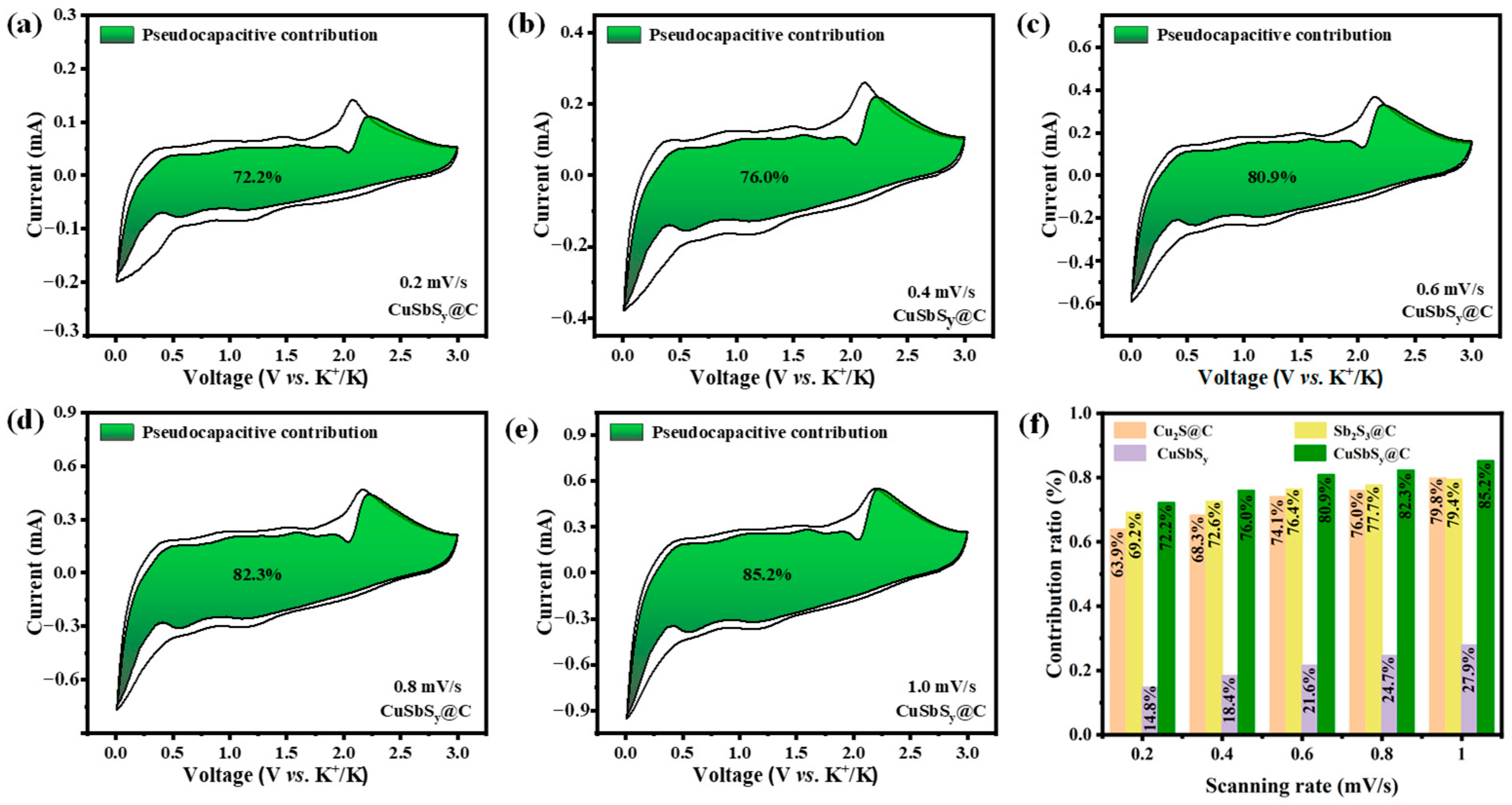
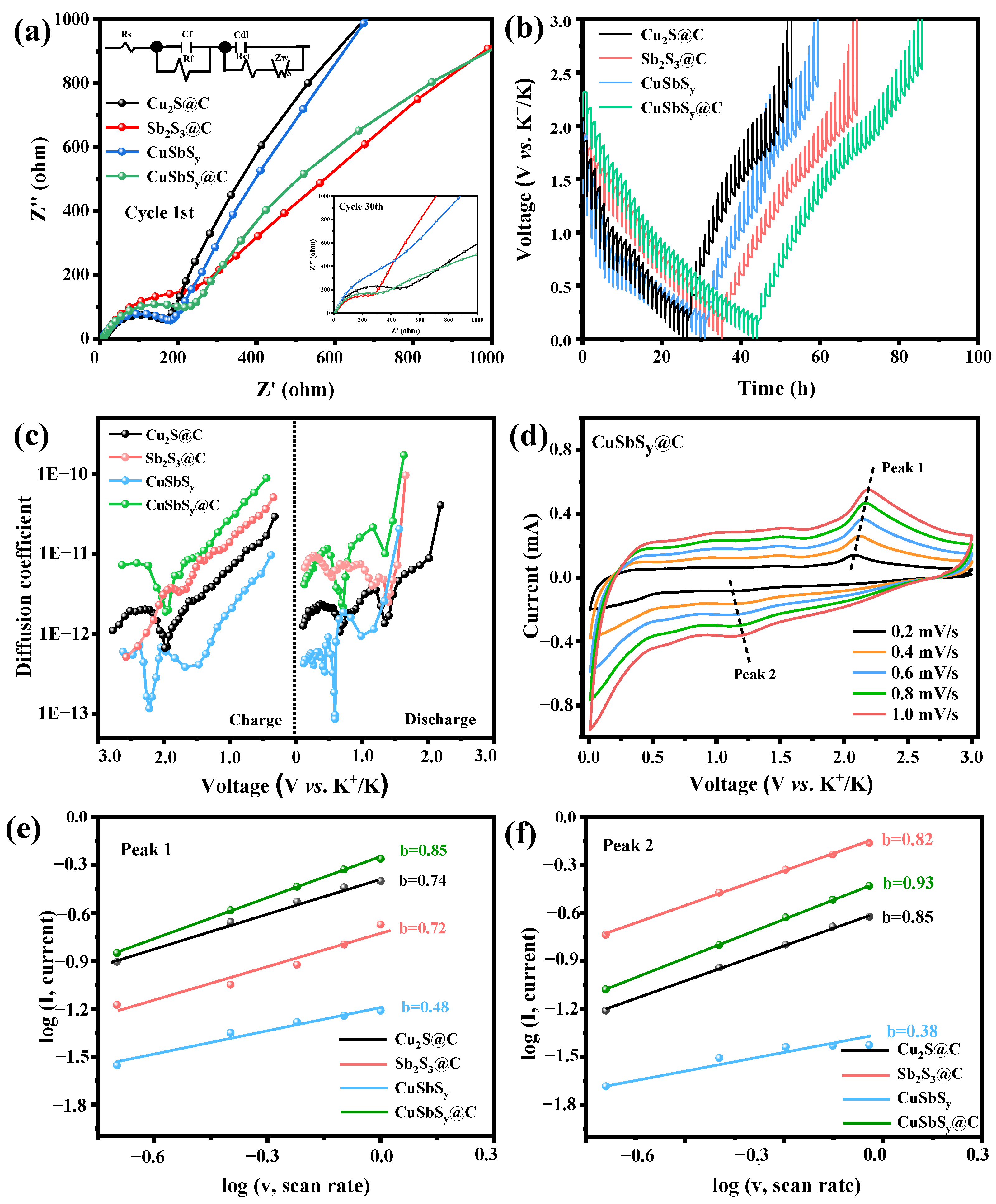
3.2. Electrochemical Performance

The performance of the CuSbSy@C anode in PIBs was investigated using cyclic voltammetry (CV) and constant current cycle tests. Figure 5a depicts the CuSbSy@C CV curve at a scan speed of 0.1 mV s−1 (0.01–3 V). Compared with Cu2S@C, Sb2S3@C, and CuSbSy, the anode of CuSbSy@C had a larger CV curve area, indicating that it had a stronger potassium storage capacity (Figure S2). CuSbSy@C exhibited a CV profile that differed significantly from that of its precursors after coating with carbon, because the coating and annealing of dopamine hydrochloride changed the structure and morphology of CuSbSy. The formation of a solid electrolyte interface (SEI) layer between the CuSbSy@C electrode and the electrolyte caused the revivification peak to appear at around 0.84 V in the first cycle of the curve [48]. The reason for another reduction peak (0.51 V) was explained as a further alloying reaction between Sb metal and K+ formed after the conversion reaction. The two characteristic peaks gradually disappeared during the subsequent charging and discharging process. There were three oxidation peaks in CuSbSy@C during charging, and the corresponding voltages were 1.03 V, 1.79 V, and 1.99 V, respectively, indicating that K+ was a multi-step depotassiation process in the active material. The new CV curve was nearly identical after the first scan, demonstrating that the CuSbSy@C electrode had positive cycle stability and electrochemical performance. The irreversible loss of specific capacity observed in charge/discharge curves for different cycle turns of CuSbSy@C at 0.1 A g−1 was explained by the development of the SEI layer and irreversible electrolyte decomposition. [49,50]. The charge/discharge curves of CuSbSy@C almost overlapped each other and maintained some stability after the first cycle, matching well with the CV curves and delivering great cycle stability (Figure 5b). In comparison to Cu2S@C, Sb2S3@C, and CuSbSy, CuSbSy@C exhibited the highest capacity and stability (Figure S3). Figure 5c shows the cycling performance with Cu2S@C, Sb2S3@C, CuSbSy, and CuSbSy@C at 100 mA g−1. From the curves, we can not only see that the CuSbSy@C had high capacity, but also verified that the carbon shell effectively improved the reliability of the CuSbSy@C. Cu2S@C, Sb2S3@C, and CuSbSy had obvious capacity attenuation after nearly 20 cycles at 100 mA g−1, while the CuSbSy@C could keep a stable charge/discharge specific capacity. In addition, the CuSbSy@C delivered remarking initial charge/discharge capacity of 423.1/632.4 mAh g−1 with an initial coulombic efficiency of 66.89%. After 60 cycles at 100 mA g−1, CuSbSy@C reserved a high specific capacity of 438.8 mAh g−1. The cycling stability of CuSbSy@C was performed at 500 mA g−1, and exhibited a high capacity of 244.2 mAh g−1 after 1000 cycles (Figure S4). After 1000 cycles at a high current density of 1000 mAh g−1, the CuSbSy@C electrode reached a high capacity of 174.5 mAh g−1 and retained 73.2% of its capacity (Figure 5d). The steadily increasing number of cycles implied that the presence of the carbon shell effectively suppressed the bulk expansion of the CuSbSy during the reaction and the unfavorable by-reactions between the electrolyte and the electrode [51,52]. As shown in Figure 5e, CuSbSy@C achieved excellent rate performance in existing bimetallic sulfides (More detailed information was in Table S2). To ulteriorly explore the rate performance of CuSbSy@C electrode for PIBs, the charge and discharge capacities were tested at different current densities in the voltage range of 0.01–3 V. (Figure 5f). CuSbSy@C electrode exhibited high reversible specific capacities of 410.8, 356.5, 318.6, 294.5, 267.3, 241.1, 213.4, and 173.6 mAh g−1 at 0.05, 0.1, 0.2, 0.3, 0.5, 1, 2, 5 A g−1, respectively. The recovered capacity is maintained at 337.5 mAh g−1 (82.2%) when the current density is restored to 0.05 A g−1, showing excellent rate performance. CuSbSy@C utilized the bimetallic synergy and carbon cladding not only obtained capacity enhancement but also improved the rate performance and long cycle life during cycling, which exhibited strongly competitive in PIBs.
To further investigate the kinetic process of potassium storage in CuSbSy@C, more electrochemical test techniques were used for us to analyze the electron/ion migration processes. A semicircle made up the high frequency (HF) portion of the Nyquist plot, and a sloping straight line made up the low frequency (LF) portion [53]. In the HF region (100 kHz–1 kHz), the resistance is mainly controlled by charge transfer, in the medium frequency (MF) region (1 kHz–1 Hz), the resistance is mainly controlled by charge transfer and diffusion, and in the LF region (<1 Hz), the resistance is mainly controlled by diffusion (Figure S5). The charge transfer resistance (Rct) between the interface of the electrodes corresponded to the semicircle, and a lower charge transfer resistance corresponded to a smaller circle radius [54]. The straight line corresponded to Warburg impedance (Zw), and the smaller the slope, the smaller the diffusion resistance of K+. Comparing the solution resistance (Rs) of four materials, the Rs of CuSbSy@C was the smallest, and that of CuSbSy was the largest (Table S3). This was due to the large contact area of the CuSbSy@C electrode with the electrolyte and the smallest contact area of the CuSbSy electrode with the electrolyte [55]. The Bode plots showed that the materials have double time constants, and the impedance fit showed that the difference between the double time constants is not very large, so the diameter of the first semicircle is small and not very significant (Figure S6). The equivalent circuit diagram of double time constants in series was obtained from the impedance fitting analysis [56]. The specific values of the time constants were given in the following Table S4. Figure 6a shows the Nyquist plots of Cu2S@C, Sb2S3@C, CuSbSy, and CuSbSy@C at 1.0 A g−1. It was obvious from the images that in the high-frequency region, CuSbSy@C shows a high charge transfer resistance (Rct = 211 Ω) after the first cycle, because there was no fast ion conductor membrane on the fresh electrode [16]. However, after 30 cycles, the resistance of Rct only increased to 315.2 Ω, much lower than the charge transfer resistance of CuSbSy (Rct = 664.2 Ω). The presence of nitrogen-doped carbon layers has also been shown to be effective in improving the electron/ion transfer capability of the CuSbSy@C. After the first cycle of CuSbSy@C, the slope of Zw in the low-frequency zone was the shortest. During the 30 cycles, the slope became smaller and smaller and finally remained unchanged, and the resistance increased steadily, which was caused by the generation of a stable SEI layer [57]. These results again demonstrated the importance of the presence of the nitrogen-doped carbon layer for improving the electrical conductivity and stability of CuSbSy@C. The kinetics of the K+ diffusion behavior of Cu2S@C, Sb2S3@C, CuSbSy, and CuSbSy@C electrodes during electrochemical processes were compared by GITT. Figure 6b,c shows the galvanostatic intermittent titration technique (GITT) curves for Cu2S@C, Sb2S3@C, CuSbSy, and CuSbSy@C at 0.1 A g−1 and the K+ diffusion coefficient DK in relation to voltage during the charging and discharging. Compared with other electrode materials, the CuSbSy@C electrode had the smallest overpotential. Also, the DK value of the CuSbSy@C electrode was higher than that of Cu2S@C, Sb2S3@C, and CuSbSy electrode during the charging. In summary, the CuSbSy@C electrode had the fastest K+ diffusion kinetics during the electrochemical reaction.
To reveal the reason for the excellent reversibility formation of CuSbSy@C, CV curves in the 0.2–1.0 mV s−1 range for various sweep speeds were measured. (Figure S7). As shown in Figure 6d, the outstanding reversibility of the material is demonstrated by the CV curves, which did not noticeably change as the peak current increased with the scan rate. Equation (1) give the scan rate (v) and peak current (i) of CuSbSy@C during the CV test [58]:
i = a v b
For calculation convenience, the formula is simplified to Equation (2):
L o g i = b log v + log a
The simplified equation shows that the b-value depends on the slope of the logarithmic relationship between log(i) and log(v). In general, the electrochemical reaction primarily displays pseudocapacitive behavior when the b-value is close to 1.0, and the ion diffusion behavior when the b-value is close to 0.5 [59]. The b-value calculated from the curves of Figure 6e,f for the different peaks are 0.85 and 0.93, b-values close to 1.0 show that the pseudocapacitive contribution accounts for the majority of the capacity. Subsequently, to quantify the percentage contribution of the pseudocapacitive, Equation (3) is used to calculate.
i = k 1 v + k 2 v 1 / 2
In the formula, i represents the current value at a fixed voltage, the contribution of the capacitive process is represented by k1v, and the contribution of the diffusion control process is denoted by k2v1/2 [60]. As shown in Figure 7a–e, the pseudocapacitive contribution of CuSbSy@C increased from 72.2% to 85.2% as the scanning rate increased from 0.2 to 1.0 mV s−1. Compared with Cu2S@C, Sb2S3@C, and CuSbSy, the pseudocapacitive contribution of CuSbSy@C was the highest (Figure 7f), which is probably better explains why the core-shell of CuSbSy@C electrode material is more favorable for K+ storage.

4. Conclusions

In summary, in situ precipitation and carbonization were used to create CuSbSy@C nanospheres with a distinctive yolk-shell structure. The internal bimetallic sulfide CuSbSy makes use of the synergistic interaction between Cu and Sb to boost overall specific capacity while also reducing volume expansion and enhancing structural stability. The external nitrogen-doped carbon shell protects the material and confines the bimetallic compound to a limited space, making it more stable and providing longer cycle life. Thus, the CuSbSy@C electrode maintains an appreciable reversible capacity (438.8 mAh g−1 after 60 cycles at 100 mA g−1), a good rate capability (173.6 mAh g−1 at 5.0 A g−1), and superior long cycle life (174.5 mAh g−1 after 1000 cycles at 1000 mA g−1).

Supplementary Materials

The following supporting information can be downloaded at: https://www.mdpi.com/article/10.3390/batteries9050238/s1, Instrumentation and Sample Analysis. Electrochemical measurement. Figure S1: XRD patterns of (a) Cu2S@C, (b) Sb2S3@C, (c) CuSbSy. Figure S2. Initial ten CV curves of (a) Cu2S@C, (b) Sb2S3@C, and (c) CuSbSy electrode at a scan rate of 0.1 mV s−1 in a potential range from 0.01–3 V. Figure S3. Charge/discharge profiles of (a) Cu2S@C, (b) Sb2S3@C, and (c) CuSbSy electrodes within the potential of 0.01–3 V at a current density of 0.1 A g−1. Figure S4. Cycling performance of CuSbSy@C electrodes at current densities of 0.5 A g−1. Figure S5. The positions of Cu2S@C, Sb2S3@C, CuSbSy, and CuSbSy@C at (a) 100 kHz, (b) 1 kHz, and (c) 1 Hz. Figure S6. Bode plots of (a) Cu2S@C, (b) Sb2S3@C, (c) CuSbSy, and (d) CuSbSy@C electrode. Figure S7. CV curves of (a) Cu2S@C, (b) Sb2S3@C, and (c) CuSbSy electrode at various scan rates of 0.2–1.0 mV s−1. Table S1. Content of Cu, Sb, and S elements in the compounds. Table S2. Performance comparison between this study and existing studies. Table S3. The comparison of Rs, RSEI, and Rct of Cu2S@C, Sb2S3@C, CuSbSy, and CuSbSy@C. Table S4. The comparison of τ1, and τ2 of Cu2S@C, Sb2S3@C, CuSbSy, and CuSbSy@C.

Author Contributions

Conceptualization, P.H. and G.Y.; methodology, P.H. and Y.D.; software, P.H., X.C. and G.Y.; validation, P.H., X.C. and S.H.; formal analysis, P.H. and Y.D.; investigation, P.H.; resources, Y.L.; data curation, P.H.; writing—original draft preparation, P.H.; writing—review and editing, Y.D., H.Z. and Y.L.; visualization, Y.L.; supervision, Q.F. and Y.L.; project administration, Y.L.; funding acquisition, Q.F. and Y.L. All authors have read and agreed to the published version of the manuscript.

Funding

This work was supported by the National Natural Science Foundation of China (22076116) and the Sino-German Center for Research Promotion (GZ1579).

Institutional Review Board Statement

Not applicable.

Informed Consent Statement

Not applicable.

Data Availability Statement

The data that support the findings of this study are available from the corresponding author upon reasonable request.

Conflicts of Interest

The authors declare no conflict of interest.

References

  1. Zhang, W.; Yin, J.; Wang, W.; Bayhan, Z.; Alshareef, H.N. Status of Rechargeable Potassium Batteries. Nano Energy 2021, 83, 105792. [Google Scholar] [CrossRef]
  2. Sha, M.; Liu, L.; Zhao, H.; Lei, Y. Anode Materials for Potassium-Ion Batteries: Current Status and Prospects. Carbon Energy 2020, 2, 350–369. [Google Scholar] [CrossRef]
  3. Anoopkumar, V.; John, B.; Td, M. Potassium-Ion Batteries: Key to Future Large-Scale Energy Storage? ACS Appl. Energy Mater. 2020, 3, 9478–9492. [Google Scholar]
  4. Zhang, Q.; Wang, Z.; Zhang, S.; Zhou, T.; Mao, J.; Guo, Z. Cathode Materials for Potassium-Ion Batteries: Current Status and Perspective. Electrochem. Energy Rev. 2018, 1, 625–658. [Google Scholar] [CrossRef]
  5. Khan, N.; Han, G.; Mazari, S.A. Carbon Nanotubes-Based Anode Materials for Potassium Ion Batteries: A Review. J. Electroanal. Chem. 2022, 907, 116051. [Google Scholar] [CrossRef]
  6. Hong, Z.; Maleki, H.; Ludwig, T.; Zhen, Y.; Wilhelm, M.; Lee, D.; Kim, K.-H.; Mathur, S. New Insights into Carbon-Based and Mxene Anodes for Na and K-Ion Storage: A Review. J. Energy Chem. 2021, 62, 660–691. [Google Scholar] [CrossRef]
  7. Ma, L.; Lv, Y.; Wu, J.; Xia, C.; Kang, Q.; Zhang, Y.; Liang, H.; Jin, Z. Recent Advances in Anode Materials for Potassium-Ion Batteries: A Review. Nano Res. 2021, 14, 4442–4470. [Google Scholar] [CrossRef]
  8. Li, L.; Hu, Z.; Liu, Q.; Wang, J.-Z.; Guo, Z.; Liu, H.-K. Cathode Materials for High-Performance Potassium-Ion Batteries. Cell Rep. Phys. Sci. 2021, 2, 100657. [Google Scholar] [CrossRef]
  9. Bin, D.-S.; Xu, Y.-S.; Guo, S.-J.; Sun, Y.-G.; Cao, A.-M.; Wan, L.-J. Manipulating Particle Chemistry for Hollow Carbon-Based Nanospheres: Synthesis Strategies, Mechanistic Insights, and Electrochemical Applications. Acc. Chem. Res. 2021, 54, 221–231. [Google Scholar] [CrossRef] [PubMed]
  10. Qi, X.; Huang, K.; Wu, X.; Zhao, W.; Wang, H.; Zhuang, Q.; Ju, Z. Novel Fabrication of N-Doped Hierarchically Porous Carbon with Exceptional Potassium Storage Properties. Carbon 2018, 131, 79–85. [Google Scholar] [CrossRef]
  11. Wang, D.; Zhang, J.; Li, X.; Liu, L.; Yuan, M.; Cao, B.; Li, A.; Chen, X.; Yang, R.; Song, H. Woven Microsphere Architected by Carbon Nanotubes as High-Performance Potassium Ion Batteries Anodes. Chem. Eng. J. 2022, 429, 132272. [Google Scholar] [CrossRef]
  12. Desai, A.V.; Morris, R.E.; Armstrong, A.R. Advances in Organic Anode Materials for Na-/K-Ion Rechargeable Batteries. ChemSusChem 2020, 13, 4866–4884. [Google Scholar] [CrossRef]
  13. Wolfson, E.R.; Schkeryantz, L.; Moscarello, E.M.; Fernandez, J.P.; Paszek, J.; Wu, Y.; Hadad, C.M.; McGrier, P.L. Alkynyl-Based Covalent Organic Frameworks as High-Performance Anode Materials for Potassium-Ion Batteries. ACS Appl. Mater. Interfaces 2021, 13, 41628–41636. [Google Scholar] [CrossRef] [PubMed]
  14. Zhu, H.; Liu, T.; Peng, L.; Yao, W.; Kang, F.; Shu, J.; Yang, C. A Compact Bi2WO6 Microflowers Anode for Potassium-Ion Storage: Taming a Sequential Phase Evolution toward Stable Electrochemical Cycling. Nano Energy 2021, 82, 105784. [Google Scholar] [CrossRef]
  15. Wang, J.; Wang, B.; Liu, Z.; Fan, L.; Zhang, Q.; Ding, H.; Wang, L.; Yang, H.; Yu, X.; Lu, B. Nature of Bimetallic Oxide Sb2MoO6/rGo Anode for High-Performance Potassium-Ion Batteries. Adv. Sci. Lett. 2019, 6, 1900904. [Google Scholar]
  16. Chen, X.; Cheng, N.; Zhang, L.; Xiang, G.; Ding, Y.-L.; Liu, Z. Flower-Like Spherical FeCoS2 Coated by Reduced Graphene Oxide as Anode for High Performance Potassium Ion Storage. J. Alloys Compd. 2021, 861, 158458. [Google Scholar] [CrossRef]
  17. Iqbal, S.; Wang, L.; Kong, Z.; Zhai, Y.; Sun, X.; Wang, F.; Jing, Z.; He, X.; Dou, J.; Xu, L. In Situ Growth of CoS2/ZnS Nanoparticles on Graphene Sheets as an Ultralong Cycling Stability. ACS Appl. Mater. Interfaces 2022, 14, 15324–15336. [Google Scholar] [CrossRef]
  18. Xu, Y.; Liu, X.; Su, H.; Jiang, S.; Zhang, J.; Li, D. Hierarchical Bimetallic Selenides CoSe2–MoSe2/rGo for Sodium/Potassium-Ion Batteries Anode: Insights into the Intercalation and Conversion Mechanism. Energy Environ. Mater. 2022, 5, 627–636. [Google Scholar] [CrossRef]
  19. Chu, J.; Yu, Q.; Yang, D.; Xing, L.; Lao, C.-Y.; Wang, M.; Han, K.; Liu, Z.; Zhang, L.; Du, W.; et al. Thickness-Control of Ultrathin Bimetallic Fe–Mo Selenide@N-Doped Carbon Core/Shell “Nano-Crisps” for High-Performance Potassium-Ion Batteries. Appl. Mater. Today 2018, 13, 344–351. [Google Scholar] [CrossRef]
  20. Wu, Y.; Yi, Y.; Sun, Z.; Sun, H.; Guo, T.; Zhang, M.; Cui, L.; Jiang, K.; Peng, Y.; Sun, J. Bimetallic Fe-Ni Phosphide Carved Nanoframes toward Efficient Overall Water Splitting and Potassium-Ion Storage. Chem. Eng. J. 2020, 390, 124515. [Google Scholar] [CrossRef]
  21. Chen, K.-T.; Tuan, H.-Y. Bi–Sb Nanocrystals Embedded in Phosphorus as High-Performance Potassium Ion Battery Electrodes. ACS Nano 2020, 14, 11648–11661. [Google Scholar] [CrossRef] [PubMed]
  22. Wu, Y.; Zhang, C.; Zhao, H.; Lei, Y. Recent Advances in Ferromagnetic Metal Sulfides and Selenides as Anodes for Sodium- and Potassium-Ion Batteries. J. Mater. Chem. A 2021, 9, 9506–9534. [Google Scholar] [CrossRef]
  23. Wu, J.; Liu, S.; Rehman, Y.; Huang, T.; Zhao, J.; Gu, Q.; Mao, J.; Guo, Z. Phase Engineering of Nickel Sulfides to Boost Sodium- and Potassium-Ion Storage Performance. Adv. Funct. Mater. 2021, 31, 2010832. [Google Scholar] [CrossRef]
  24. Dong, Y.; Xu, Y.; Li, W.; Fu, Q.; Wu, M.; Manske, E.; Kröger, J.; Lei, Y. Insights into the Crystallinity of Layer-Structured Transition Metal Dichalcogenides on Potassium Ion Battery Performance: A Case Study of Molybdenum Disulfide. Small 2019, 15, 1900497. [Google Scholar] [CrossRef] [PubMed]
  25. Dong, Y.; Yan, C.; Zhao, H.; Lei, Y. Recent Advances in 2D Heterostructures as Advanced Electrode Materials for Potassium-Ion Batteries. Small Struct. 2022, 3, 2100221. [Google Scholar] [CrossRef]
  26. Liu, Q.; Han, F.; Zhou, J.; Li, Y.; Chen, L.; Zhang, F.; Zhou, D.; Ye, C.; Yang, J.; Wu, X.; et al. Boosting the Potassium-Ion Storage Performance in Soft Carbon Anodes by the Synergistic Effect of Optimized Molten Salt Medium and N/S Dual-Doping. ACS Appl. Mater. Interfaces 2020, 12, 20838–20848. [Google Scholar] [CrossRef]
  27. Huang, H.; Etogo, C.A.; Chen, C.; Bi, R.; Zhang, L. Realizing Fast Diffusion Kinetics Based on Three-Dimensional Ordered Macroporous Cu9S5@C for Potassium-Ion Batteries. ACS Appl. Mater. Interfaces 2021, 13, 36982–36991. [Google Scholar] [CrossRef]
  28. Wang, C.; Lu, J.; Tong, H.; Wu, S.; Wang, D.; Liu, B.; Cheng, L.; Lin, Z.; Hu, L.; Wang, H.; et al. Structural Engineering of Sulfur-Doped Carbon Encapsulated Bismuth Sulfide Core-Shell Structure for Enhanced Potassium Storage Performance. Nano Res. 2021, 14, 3545–3551. [Google Scholar] [CrossRef]
  29. Yang, S.H.; Park, S.-K.; Park, G.D.; Kim, J.H.; Kang, Y.C. Rational Synthesis of Uniform Yolk–Shell Ni–Fe Bimetallic Sulfide Nanoflakes@Porous Carbon Nanospheres as Advanced Anodes for High-Performance Potassium-/Sodium-Ion Batteries. Chem. Eng. J. 2021, 417, 127963. [Google Scholar] [CrossRef]
  30. Chen, J.; Zhang, Y.; Chen, C.; Tian, N.; Zhang, Q.; Zhang, B. Graphene Wrapped Cobalt/Tin Bimetallic Sulfides Composites with Abundant Active Facets and Extended Interlayer Spacing for Stable Sodium/Potassium Storage. Chem. Eng. J. 2022, 442, 136223. [Google Scholar] [CrossRef]
  31. Wang, J.; Fan, L.; Liu, Z.; Chen, S.; Zhang, Q.; Wang, L.; Yang, H.; Yu, X.; Lu, B. In Situ Alloying Strategy for Exceptional Potassium Ion Batteries. ACS Nano 2019, 13, 3703–3713. [Google Scholar] [CrossRef]
  32. Zhang, W.; Chen, J.; Liu, Y.; Liu, S.; Li, X.; Yang, K.; Li, L. Decoration of Hollow Nitrogen-Doped Carbon Nanofibers with Tapered Rod-Shaped NiCo2S4 as a 3D Structural High-Rate and Long-Lifespan Self-Supported Anode Material for Potassium-Ion Batteries. J. Alloys Compd. 2020, 823, 153631. [Google Scholar] [CrossRef]
  33. Chang, C.-B.; Chen, K.-T.; Tuan, H.-Y. Large-Scale Synthesis of Few-Layered Copper Antimony Sulfide Nanosheets as Electrode Materials for High-Rate Potassium-Ion Storage. J. Colloid Interface Sci. 2022, 608, 984–994. [Google Scholar] [CrossRef]
  34. Yang, F.; Gao, H.; Hao, J.; Zhang, S.; Li, P.; Liu, Y.; Chen, J.; Guo, Z. Yolk–Shell Structured FeP@C Nanoboxes as Advanced Anode Materials for Rechargeable Lithium-/Potassium-Ion Batteries. Adv. Funct. Mater. 2019, 29, 1808291. [Google Scholar] [CrossRef]
  35. Zhao, Y.; Zhu, J.; Ong, S.J.H.; Yao, Q.; Shi, X.; Hou, K.; Xu, Z.J.; Guan, L. High-Rate and Ultralong Cycle-Life Potassium Ion Batteries Enabled by in Situ Engineering of Yolk–Shell FeS2@C Structure on Graphene Matrix. Adv. Energy Mater. 2018, 8, 1802565. [Google Scholar] [CrossRef]
  36. Chu, J.; Yu, Q.; Han, K.; Xing, L.; Gu, C.; Li, Y.; Bao, Y.; Wang, W. Yolk–Shell Structured FeS/MoS2@Nitrogen-Doped Carbon Nanocubes with Sufficient Internal Void Space as an Ultrastable Anode for Potassium-Ion Batteries. J. Mater. Chem. A 2020, 8, 23983–23993. [Google Scholar] [CrossRef]
  37. Wang, W.; Zhi, G.; Liu, L.; Cao, L.; Xie, J.; Sun, L.; Hao, L.; Yao, H. Preparation of Rod-Like CuSbS2 Particles by Soft-Template Synthesis and Electrochemical Performance toward Lithium Storage. J. Nanopart. Res. 2022, 24, 98. [Google Scholar] [CrossRef]
  38. Wang, S.; Zhang, Z.; Wang, Y.; Han, M. Hierarchical Hollow CuSbS2 Microspheres with Excellent Photoelectrochemical Properties. Mater. Lett.-X. 2021, 12, 100094. [Google Scholar] [CrossRef]
  39. Wan, L.; Ma, C.; Hu, K.; Zhou, R.; Mao, X.; Pan, S.; Wong, L.H.; Xu, J. Two-Stage Co-Evaporated CuSbS2 Thin Films for Solar Cells. J. Alloys Compd. 2016, 680, 182–190. [Google Scholar] [CrossRef]
  40. Smith, J.M.; Wren, J.C.; Odziemkowski, M.; Shoesmith, D.W. The Electrochemical Response of Preoxidized Copper in Aqueous Sulfide Solutions. J. Electrochem. Soc. 2007, 154, C431. [Google Scholar] [CrossRef]
  41. Zhang, P.; Zhu, Q.; Wei, Y.; Xu, B. Achieving Stable and Fast Potassium Storage of Sb2S3@Mxene Anode Via Interfacial Bonding and Electrolyte Chemistry. Chem. Eng. J. 2023, 451, 138891. [Google Scholar] [CrossRef]
  42. Dutková, E.; Sayagués, M.J.; Fabián, M.; Kováč, J.; Kováč, J.; Baláž, M.; Stahorský, M. Mechanochemical Synthesis of Ternary Chalcogenide Chalcostibite CuSbS2 and Its Characterization. J. Mater. Sci. Mater. Electron. 2021, 32, 22898–22909. [Google Scholar] [CrossRef]
  43. Yi, Z.; Qian, Y.; Tian, J.; Shen, K.; Lin, N.; Qian, Y. Self-Templating Growth of Sb2Se3@C Microtube: A Convention-Alloying-Type Anode Material for Enhanced K-Ion Batteries. J. Mater. Chem. A 2019, 7, 12283–12291. [Google Scholar] [CrossRef]
  44. Wu, X.-F.; Li, Z.-J.; Liu, J.-X.; Luo, W.; Gaumet, J.-J.; Mai, L.-Q. Defect Engineering of Hierarchical Porous Carbon Microspheres for Potassium-Ion Storage. Rare Metals 2022, 41, 3446–3455. [Google Scholar] [CrossRef]
  45. Wang, H.; Xing, Z.; Hu, Z.; Zhang, Y.; Hu, Y.; Sun, Y.; Ju, Z.; Zhuang, Q. Sn-Based Submicron-Particles Encapsulated in Porous Reduced Graphene Oxide Network: Advanced Anodes for High-Rate and Long Life Potassium-Ion Batteries. Appl. Mater. Today 2019, 15, 58–66. [Google Scholar] [CrossRef]
  46. Li, W.; Wang, D.; Gong, Z.; Yin, Z.; Guo, X.; Liu, J.; Mao, C.; Zhang, Z.; Li, G. A Robust Strategy for Engineering Fe7S8/C Hybrid Nanocages Reinforced by Defect-Rich MoS2 Nanosheets for Superior Potassium-Ion Storage. ACS Nano 2020, 14, 16046–16056. [Google Scholar] [CrossRef] [PubMed]
  47. Hu, J.; Wang, B.; Yu, Q.; Zhang, Y.; Zhang, D.; Li, Y.; Wang, W. Amorphous Cobalt Sulfide/N-Doped Carbon Core/Shell Nanoparticles as an Anode Material for Potassium-Ion Storage. J. Mater. Sci. 2020, 55, 15213–15221. [Google Scholar] [CrossRef]
  48. Yu, Q.; Hu, J.; Gao, Y.; Gao, J.; Suo, G.; Zuo, P.; Wang, W.; Yin, G. Iron Sulfide/Carbon Hybrid Cluster as an Anode for Potassium-Ion Storage. J. Alloys Compd. 2018, 766, 1086–1091. [Google Scholar] [CrossRef]
  49. Wang, G.; Xiong, X.; Xie, D.; Lin, Z.; Zheng, J.; Zheng, F.; Li, Y.; Liu, Y.; Yang, C.; Liu, M. Chemically Activated Hollow Carbon Nanospheres as a High-Performance Anode Material for Potassium Ion Batteries. J. Mater. Chem. A 2018, 6, 24317–24323. [Google Scholar] [CrossRef]
  50. Zhang, B.; Zheng, Q.B.; Huang, Z.D.; Oh, S.W.; Kim, J.K. SnO2–Graphene–Carbon Nanotube Mixture for Anode Material with Improved Rate Capacities. Carbon 2011, 49, 4524–4534. [Google Scholar] [CrossRef]
  51. Li, L.; Wang, L.; Zhang, C. Hierarchical MnMoO4@Nitrogen-Doped Carbon Core-Shell Microspheres for Lithium/Potassium-Ion Batteries. J. Alloys Compd. 2022, 893, 162336. [Google Scholar] [CrossRef]
  52. Wang, D.; Ma, Q.; Tian, K.-H.; Duan, C.-Q.; Wang, Z.-Y.; Liu, Y.-G. Ultrafine Nano-Scale Cu2Sb Alloy Confined in Three-Dimensional Porous Carbon as an Anode for Sodium-Ion and Potassium-Ion Batteries. Int. J. Miner. Metall. Mater. 2021, 28, 1666–1674. [Google Scholar] [CrossRef]
  53. Peng, Q.; Zhang, S.; Yang, H.; Sheng, B.; Xu, R.; Wang, Q.; Yu, Y. Boosting Potassium Storage Performance of the Cu2S Anode Via Morphology Engineering and Electrolyte Chemistry. ACS Nano 2020, 14, 6024–6033. [Google Scholar] [CrossRef] [PubMed]
  54. Miao, W.; Zhang, Y.; Li, H.; Zhang, Z.; Li, L.; Yu, Z.; Zhang, W. ZIF-8/ZIF-67-Derived 3D Amorphous Carbon-Encapsulated CoS/Ncnts Supported on CoS-Coated Carbon Nanofibers as an Advanced Potassium-Ion Battery Anode. J. Mater. Chem. A 2019, 7, 5504–5512. [Google Scholar] [CrossRef]
  55. Merrill, M.D.; Logan, B.E. Electrolyte Effects on Hydrogen Evolution and Solution Resistance in Microbial Electrolysis Cells. J. Power Sources 2009, 191, 203–208. [Google Scholar] [CrossRef]
  56. Selvi, V.E.; Seenivasan, H.; Rajam, K.S. Electrochemical Corrosion Behavior of Pulse and Dc Electrodeposited Co–P Coatings. Surf. Coat. Technol. 2012, 206, 2199–2206. [Google Scholar] [CrossRef]
  57. Dong, Y.; Xu, C.; Li, Y.; Zhang, C.; Zhao, H.; Kaiser, U.; Lei, Y. Ultrahigh-Rate and Ultralong-Duration Sodium Storage Enabled by Sodiation-Driven Reconfiguration. Adv. Energy Mater. 2023, 2204324. [Google Scholar] [CrossRef]
  58. Wang, Y.; Liu, J.; Chen, X.; Kang, B.; Wang, H.-E.; Xiong, P.; Chen, Q.; Wei, M.; Li, N.; Qian, Q.; et al. Structural Engineering of Tin Sulfides Anchored on Nitrogen/Phosphorus Dual-Doped Carbon Nanofibres in Sodium/Potassium-Ion Batteries. Carbon 2022, 189, 46–56. [Google Scholar] [CrossRef]
  59. Yang, G.; Yan, C.; Hu, P.; Fu, Q.; Zhao, H.; Lei, Y. Synthesis of CoSe2 Reinforced Nitrogen-Doped Carbon Composites as Advanced Anodes for Potassium-Ion Batteries. Inorg. Chem. Front. 2022, 9, 3719–3727. [Google Scholar] [CrossRef]
  60. Tao, L.; Yang, Y.; Wang, H.; Zheng, Y.; Hao, H.; Song, W.; Shi, J.; Huang, M.; Mitlin, D. Sulfur-Nitrogen Rich Carbon as Stable High Capacity Potassium Ion Battery Anode: Performance and Storage Mechanisms. Energy Storage Mater. 2020, 27, 212–225. [Google Scholar] [CrossRef]
Figure 1. Schematic illustration of the synthesis process of CuSbSy@C.
Batteries 09 00238 g001
Figure 2. (ad) SEM images of Cu2S@C, Sb2S3@C, CuSbSy, and CuSbSy@C. (e) Transmission electron microscope images of CuSbSy@C. (f) Element mapping images of CuSbSy@C.
Batteries 09 00238 g002
Figure 3. (a) XRD of CuSbSy@C. (b) Raman spectra of Cu2S@C, Sb2S3@C, CuSbSy, and CuSbSy@C. (c) TGA patterns of CuSbSy@C.
Batteries 09 00238 g003
Figure 4. (a) XPS full spectra of CuSbSy@C. XPS fine spectra of (b) C 1s, (c) N 1s, (d) Cu 2p, (e) Sb 3d, and (f) S 2p.
Batteries 09 00238 g004
Figure 5. (a) CV curves of CuSbSy@C electrode. (b) Charge/discharge curves of CuSbSy@C. (c) Cycling performance of Cu2S@C, Sb2S3@C, CuSbSy, and CuSbSy@C electrodes at 0.1 A g−1 and (d) 1.0 A g−1. (e) Rate capability of CuSbSy@C and previously reported materials. (f) Rate of Cu2S@C, Sb2S3@C, CuSbSy, and CuSbSy@C from 0.05 to 5.0 A g−1.
Batteries 09 00238 g005
Figure 6. (a) Nyquist plots of Cu2S@C, Sb2S3@C, CuSbSy, and CuSbSy@C electrodes with different cycle numbers at 1.0 A g−1. (b) GITT curves of Cu2S@C, Sb2S3@C, CuSbSy, and CuSbSy@C electrodes. (c) The K+ diffusion coefficients of Cu2S@C, Sb2S3@C, CuSbSy, and CuSbSy@C electrodes during charging and discharging. (d) CV curves of CuSbSy@C at various rates. Log(i) versus log(v) for (e) peak 1, and (f) peak 2.
Batteries 09 00238 g006
Figure 7. Pseudocapacitive contribution of CuSbSy@C electrode at different rates of (a) 0.2 mV s−1, (b) 0.4 mV s−1, (c) 0.6 mV s−1, (d) 0.8 mV s−1, and (e) 1.0 mV s−1. (f) Percentage contribution of pseudocapacitive for Cu2S@C, Sb2S3@C, CuSbSy, and CuSbSy@C electrodes.
Batteries 09 00238 g007
Disclaimer/Publisher’s Note: The statements, opinions and data contained in all publications are solely those of the individual author(s) and contributor(s) and not of MDPI and/or the editor(s). MDPI and/or the editor(s) disclaim responsibility for any injury to people or property resulting from any ideas, methods, instructions or products referred to in the content.

