Article

Towards Determining an Engineering Stress-Strain Curve and Damage of the Cylindrical Lithium-Ion Battery Using the Cylindrical Indentation Test

1
Department of Civil and Environmental Engineering, Louisiana State University, Baton Rouge, LA 70803, USA
2
Institute of Structural Analysis, Poznań University of Technology, Piotrowo 5 Street, 60-965 Poznań, Poland
*
Author to whom correspondence should be addressed.
Batteries 2023, 9(4), 233; https://doi.org/10.3390/batteries9040233
Submission received: 24 February 2023 / Revised: 31 March 2023 / Accepted: 13 April 2023 / Published: 18 April 2023

Abstract

:
Mechanical internal short circuit (ISC) is one of the significant safety issues in lithium-ion battery design. As a result, it is possible to subject LIB cells to thorough mechanical abuse tests to determine when and why failure may occur. The indentation test is a recommended loading condition for evaluating mechanical damage and ISC. In this study, 18,650 cylindrical battery cells underwent indentation tests and a voltage reduction following the peak force identified by the ISC. Due to the complexity of the contact surface shape between two cylinders (LIB cell and indenter), a new phenomenological analytical model is proposed to measure the projected contact area, which the FEM model confirms. Moreover, the stress-strain curve and Young’s modulus reduction were calculated from the load-depth data. In contrast to previously published models, the model developed in this paper assumes anisotropic hyperelasticity (the transversely isotropic case) and predicts the growing load-carrying capacity (scalar damage), whose variation is regulated by the Caputo-Almeida fractional derivative.

1. Introduction

In various applications, such as electric vehicles and cell phones, lithium-ion battery (LIB) cells are considered the first choice for power batteries due to their higher capacity and higher efficiency [1]. However, the safety of electric vehicles has become a crucial issue since LIB cells can be subjected to various mechanical loading conditions [2,3]. Hence, it is essential to have a better knowledge of the damage behavior of LIB cells, which has drawn extensive attention from vehicle companies and engineering groups [4]. Furthermore, sufficient understanding in this critical field is necessary to develop reliable methods to ensure the safe application of the LIB cell under different mechanical loadings [4].
However, in terms of shape, four types of LIB cells are found in the literature, including pouch [5,6,7,8,9,10,11,12], elliptical [5,13,14,15], cylindrical [16,17,18,19,20], and prismatic [21,22,23]. Furthermore, regarding the detection of failure, various mechanical abuse tests with a range of indenters, such as nail [24,25,26,27,28,29], conical [30], hemispheric [5,6,11,19,23,30,31,32,33,34,35], cylindrical [17,31,32,33,36,37,38], flat [10,16,17,31,36,39], pinch [11], and three-point bending indenters [31] were used to induce the internal short circuit (ISC) on the whole LIB cell. These tests have been developed to address the safety concerns associated with LIB cells: the risk of failure, ISC, and thermal runaway. Consequently, many attempts have been made to develop a failure model based on a function of the plastic strain to predict the failure onset and propagation in cases of mechanically abusive loadings [31,39,40,41,42]. In contrast, the current study focuses on developing a damage model to predict material degradation through mechanical deformation.
Three primary modeling methods have been employed in the literature to evaluate the LIB cell’s response and safety risks following mechanical deformation and damage. The first method considers the LIB cell as a multi-layer structure and evaluates the mechanical properties of individual components [43]. The second approach utilizes the reduced-detail model by combining several layers into only a single one [9]. Finally, the last method considers the LIB cell as a homogenized medium with a significantly lower computational cost [44]. It should be pointed out that a homogenized model was developed in this study, which boasts higher computational efficiency than others.
However, in the literature, three isotropic, macro-homogenized material models have been developed to characterize the elastoplastic response of the LIB cell under different mechanical scenarios: power-law [41,45], hyper-foam [30,46,47], and crushable foam [30,35,46,47]. Furthermore, it should be noted that strain failure criteria have been used to predict the failure of the LIB cell in the above studies. Moreover, no explicit research is available in the literature addressing the degradation of mechanical properties due to mechanical deformation. Hence, in this study, a scalar damage model for hyperplastic materials is developed to predict the mechanisms and the extent of damage to the LIB cells in the case of the indentation test.
From the continuum damage mechanics perspective, it is widely accepted that changes in the macroscopic material properties (such as stiffness and Young’s modulus) can indicate the onset, growth, and combination of microcracks and microvoids [48,49]. Consequently, characterizing Young’s modulus of LIB cell under mechanical abuse deformation is crucial to understanding how this degradation of mechanical properties is related to an appropriate damage function. Therefore, the reduction in Young’s modulus in the computational continuum damage model is evaluated to indicate the damage onset and propagation through mechanical deformation.
Ali et al. [46] proposed a homogenized model based on the hyper-foam material model, using the strain energy function to represent the LIB cell’s mechanical behavior under in-plane constrained compression tests. While such models may be used widely to predict elastoplastic behavior, they cannot predict damage in the LIB cell. To address this, the current study evaluates LIB cells’ response under mechanical abuse tests using a combination of anisotropic hyperelasticity and the time-fractional damage evolution law within a phenomenological framework. The anisotropy is introduced through the fundamental rule that the effective (undamaged) Helmholtz free-energy function ( Ψ ˜ ) is an isotropic tensor function, including the deformation gradient ( F ) and a structural tensor ( M ). It should be noted that physically observed damage was modeled using a scalar variable ( ϕ ), which was isotropic and whose evolution was defined based on the Perzyna model [50]. Moreover, it introduces the rate dependence and implicit space-length scale (through relaxation time). Additionally, damage evolution is governed by using the Caputo-Almeida fractional derivative operator ( D t α , Ψ t l t C ) Almeida [51], which incorporates a memory (time-length scale).
Since indentation is a versatile experimental test that can easily be used to evaluate the LIB cell’s response to plastic deformation and damage propagation, an indentation test was employed in this study. Furthermore, the present study developed a novel approach to capture the reduction in the Young’s modulus due to damage in the LIB cell and convert the indentation load-depth data into the stress-strain relationship. Initially, the sink-in and elastic deflection were taken into account to measure the reduced Young’s modulus and the projected contact area. Subsequently, researchers presented an effort to modify the reported hyperelastic model in the literature to make it more suitable for the LIB cell by including softening directly in the expression for damage accumulation.

2. Materials and Methods

The LIB samples used in this study were 18,650 cylindrical LIB cells with a voltage of 3.52 V, which were 65 mm in length and 18 mm in diameter. The experimental indentation tests were performed using electromechanical MTS Insight with 100 kN load cell. For the indentation tests, a rigid cylindrical steel rod was used as the indenter with a 16 mm diameter, and LIB cells were placed on the lower plate (as seen in Figure 1). A temporary holder was used to ensure the first connection between the cell and the indenter was created, which minimized the misalignment and rotation in the battery cell. Five maximum penetration depths (2, 3, 4, 5, and 6 mm) were used to measure the reduction in the Young’s modulus through the indentation test. The LIB cell was subjected to a 2 mm displacement, the second cell to a 3 mm displacement, and so on, and the loading speed was 1 mm min−1 to extract the stress-strain relation from force-depth data. In addition, it is important to note that the indenter load direction and the cell seam are parallel, which significantly influences the experimental setup and the subsequent observations reported in this work. However, the in-situ voltage of LIB cells during indentation tests was measured by an Agilent 34410A Digital Multimeter. This study uses the voltage technique to predict the internal short circuit (ISC) and detects the force drop that coincides with when the voltage drops to 0 V.

3. Results and Discussion

3.1. Measurement of Young’s Modulus Reduction

From the homogenized model respective, the tensile or axial compression test was used to obtain Young’s modulus values for the LIB cell [31]. In the literature [33,36], a constant value, 1.5 MPa, was reported as Young’s modulus of the jellyroll. However, this definition of Young’s modulus cannot describe the elastic modulus reduction due to the damage accumulation. Therefore, this study employed the indentation test to measure the reduction of Young’s modulus through the indentation test.
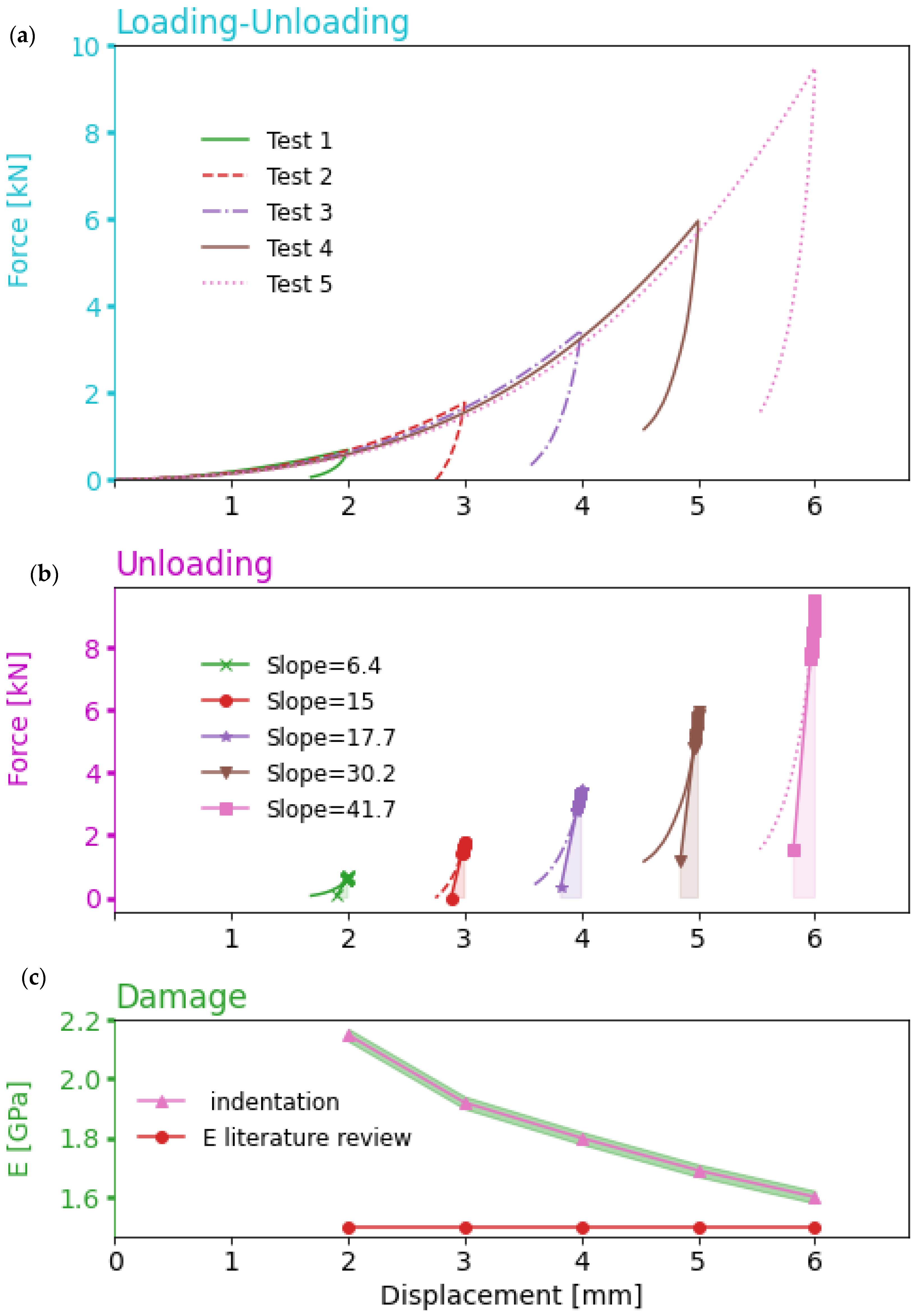
A multistep indentation test was performed to measure Young’s modulus at various depths. This section performed single-loading indentation tests at five maximum penetration depths (2, 3, 4, 5, and 6 mm). The multistep indentation test provides more information about the material properties of LIB cells in a shorter time by giving information about load/reload at each step. However, as suggested by Doerner-Nix [52], a linear fit function was used for the initial 20% of the unloading segment to evaluate Young’s modulus during the indentation test.
According to Hertz’s theory of contact mechanics between two isotropic elastic solids [52], from the unloading part, the relation between the load (P) and the penetration depth (h) during the indentation test is defined as:
P = 4 3 E eff R eff 1 2 h e h e
where h e is elastic penetration depth. Effective Young’s modulus ( E eff ) and effective radius ( R eff ) are obtained as follows:
E eff = E c E i 1 v c E i + 1 v i E c
R eff = R c R i R c + R i
where E c ,   v c , R c and E i , v i , R i denote Young’s modulus, Poisson’s ratio, the LIB cell’s radius, and the corresponding indenter’s properties. Then, based on the linear approach to measuring an appropriate fit of the unloading segment, as seen in Figure 2, the contact stiffness, S, is experimentally obtained, which can also be analytically calculated by taking the first derivative of Equation (1):
S = dP dh = E eff R eff h e 1 2
Therefore, the reduced Young’s modulus can be expressed in terms of the contact stiffness and the indentation depth obtained by combing Equations (1) and (4) as:
E ff = S R eff h e = S A c
where A c is the projected contact area, and an analytical approach will be introduced to calculate its value in the following section. The above equation confirms that Young’s modulus involves the projected contact area and the unload’s slope at the maximum depth point. Figure 2 shows that the unloading slope at the maximum depth point increased as the depth increased. However, simultaneously, the value of the projected contact area was raised. This test indicated that Young’s modulus decreased as the depth increased, which can result from damage accumulation. In the literature [35,53], a constant value used for Young’s modulus is most often considered as the LIB cell under mechanical abuse test in the computational simulations. However, in this study, a novel way was used to combine a couple of the concepts of the continuum damage mechanic and the experimental indentation test to show the degradation of Young’s modulus with increasing penetration depth, as seen in Figure 2. The rationale for using the reduction of Young’s modulus is to better describe the effect of the voids and cracks on the decrease in mechanical properties of the LIB cell. An analytical damage model will be introduced in the following sections.

3.2. Analytical Approach to Convert Force-Depth into Stress-Strain Relation

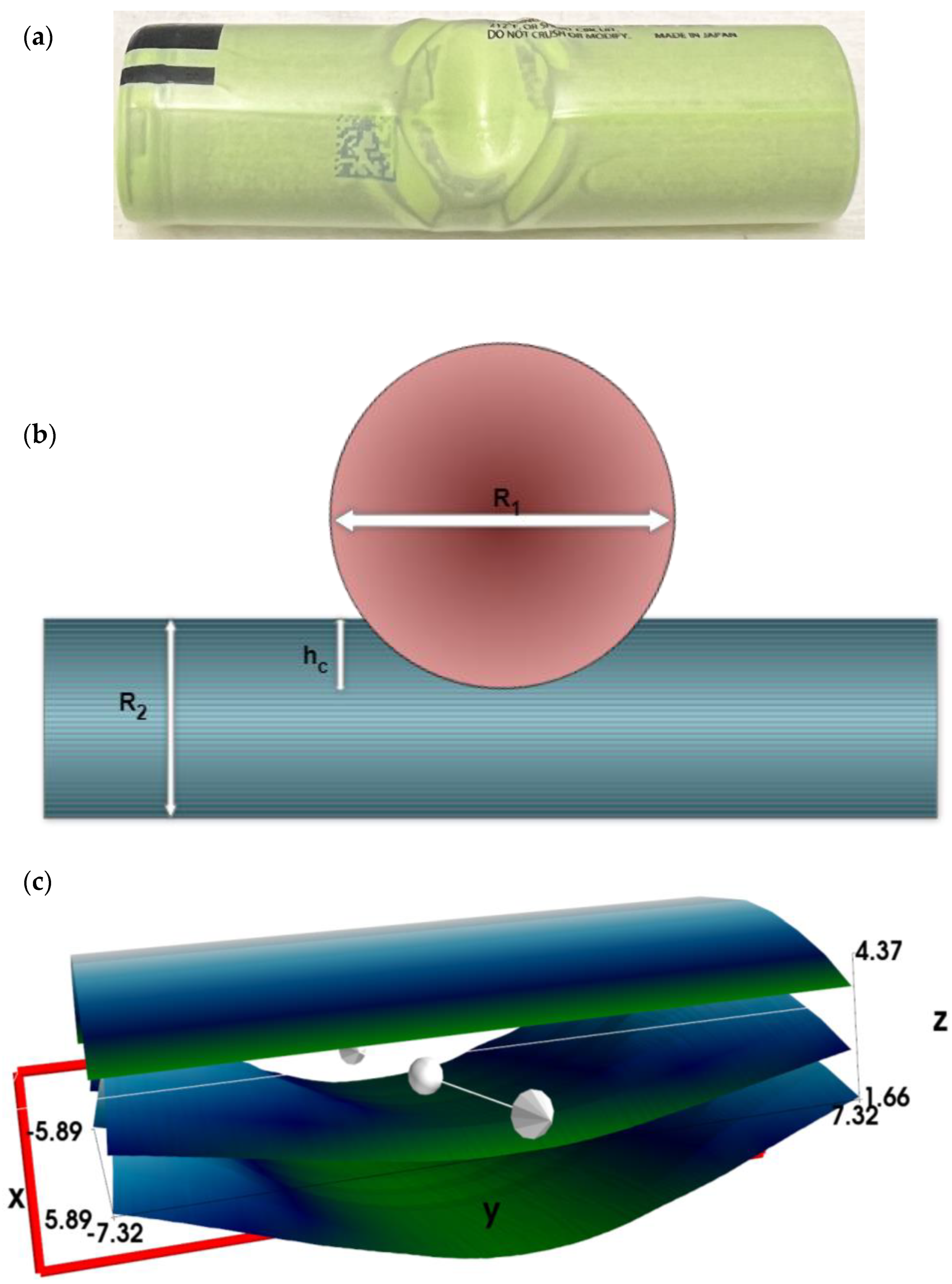
One of the challenges in the indentation test is determining the projected contact area between two crossed cylinders (the indenter and LIB cell). In this study, an analytical approach was developed to calculate the projected contact area as a function of the indenter depth. As the experimental results show in Figure 3a, the deformed area has an elliptical shape. According to Hertz’s theory, Popov [54] proposed a model to measure the contact area between two perpendicular cylinders with a radius R 1   and   R 2 (as seen in Figure 3b) to calculate the semi-axes of an ellipse as follows:
a = R 1 h c
b = R 2 h c
where h c is the contact depth being derived as a function of the maximum indenter depth ( h max ) in this study, as follows:
h c = 0.75 h max
Hence, the projected contact area ( A c ) can be obtained as:
A c = π ab = π h c R 1 R 2
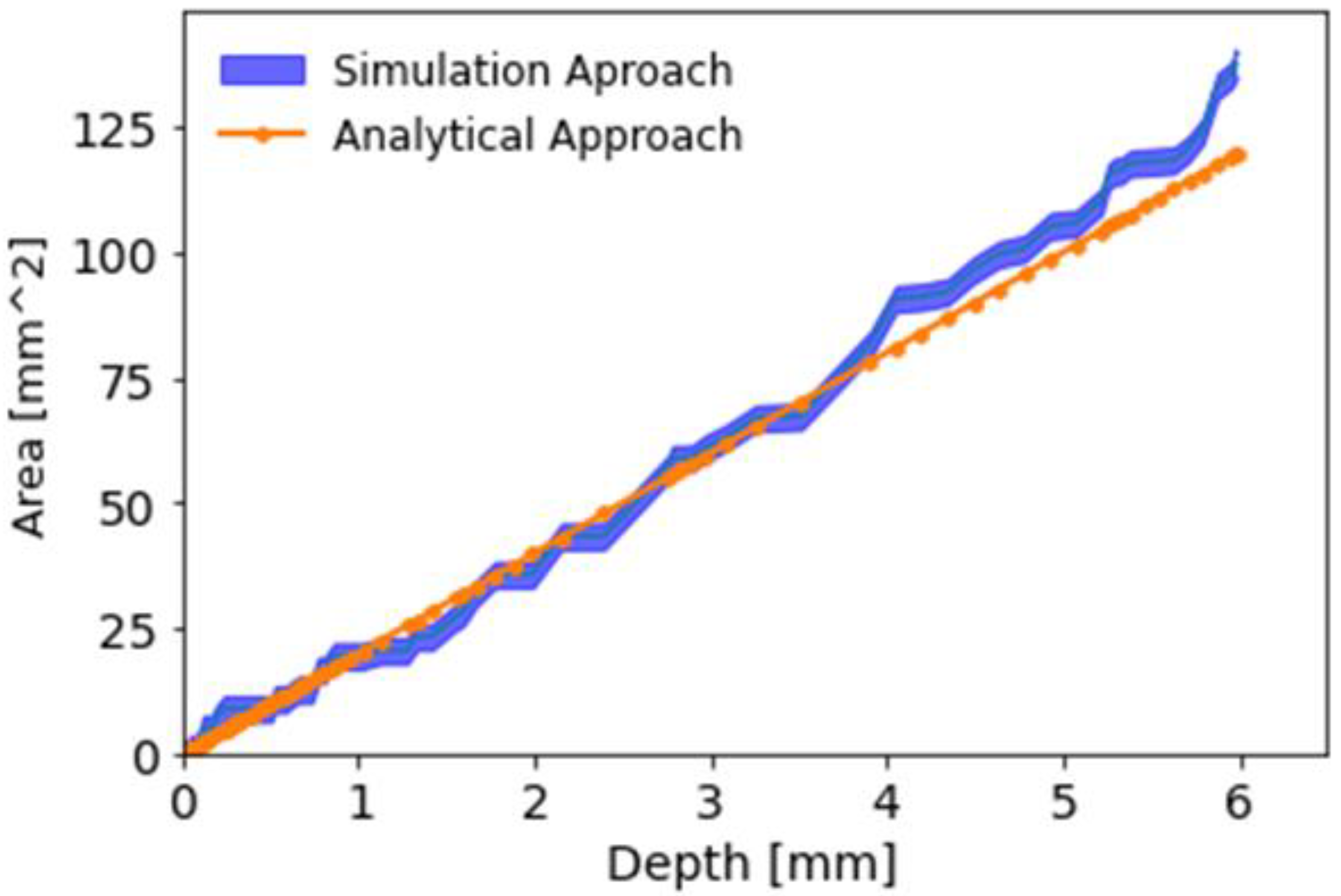
Moreover, a finite element method (ABAQUS) is used to track deformation during the indentation test. To obtain the 3D cloud point data from the 3D mesh, a custom-made Python script was developed to read/extract data from the “odb” file and obtain the node depth/position from the contact area between the two crossed cylinders, as shown in Figure 3b. Hence, the projected contact measured from the FE model at successive indentation depth stages can verify the analytical solution for measuring the projected contact area, as shown in Figure 4.
Figure 5 shows that the cell voltage drops at a depth value of approximately 6.2 mm in indentation testing. Noting that the drop in voltage and peak force occur simultaneously confirms the presence of ISC. Moreover, the main objective of this study is to characterize the elastoplastic response of the LIB cell under the indentation test. Many attempts have been made in the literature to determine stress-strain curves of the LIB cell from axial and radial compression tests [13,16,41,44,55]. Since the indentation test is one of the typical mechanical abuse tests to trigger ISC, it is challenging to calculate the stress-strain curve from the force depth data from the indentation test rather than the axial compression test. Hence, in this section the projected contact area, measured in the previous section, is used to propose a new analytical method presented in this section to calculate the stress-strain relation. From the analytical point of view, one defines effective stress ( σ eff ) as:
σ eff = 1 α P A c = 1 α P π h c R eff
where α is the stress constraint factor.
In contrast to the previous studies in the literature [56,57], due to the difficulties involved in calculating the contact area, it came to the attention of the authors to define the indentation strain in novel ways as follows:
ε xx = a R eff
ε yy = b R eff
ε zz = h c R eff
The effective indentation strain can be calculated as follows:
ε eff = 1 β 3 2 ε xx 2 + ε yy 2 + ε zz 2
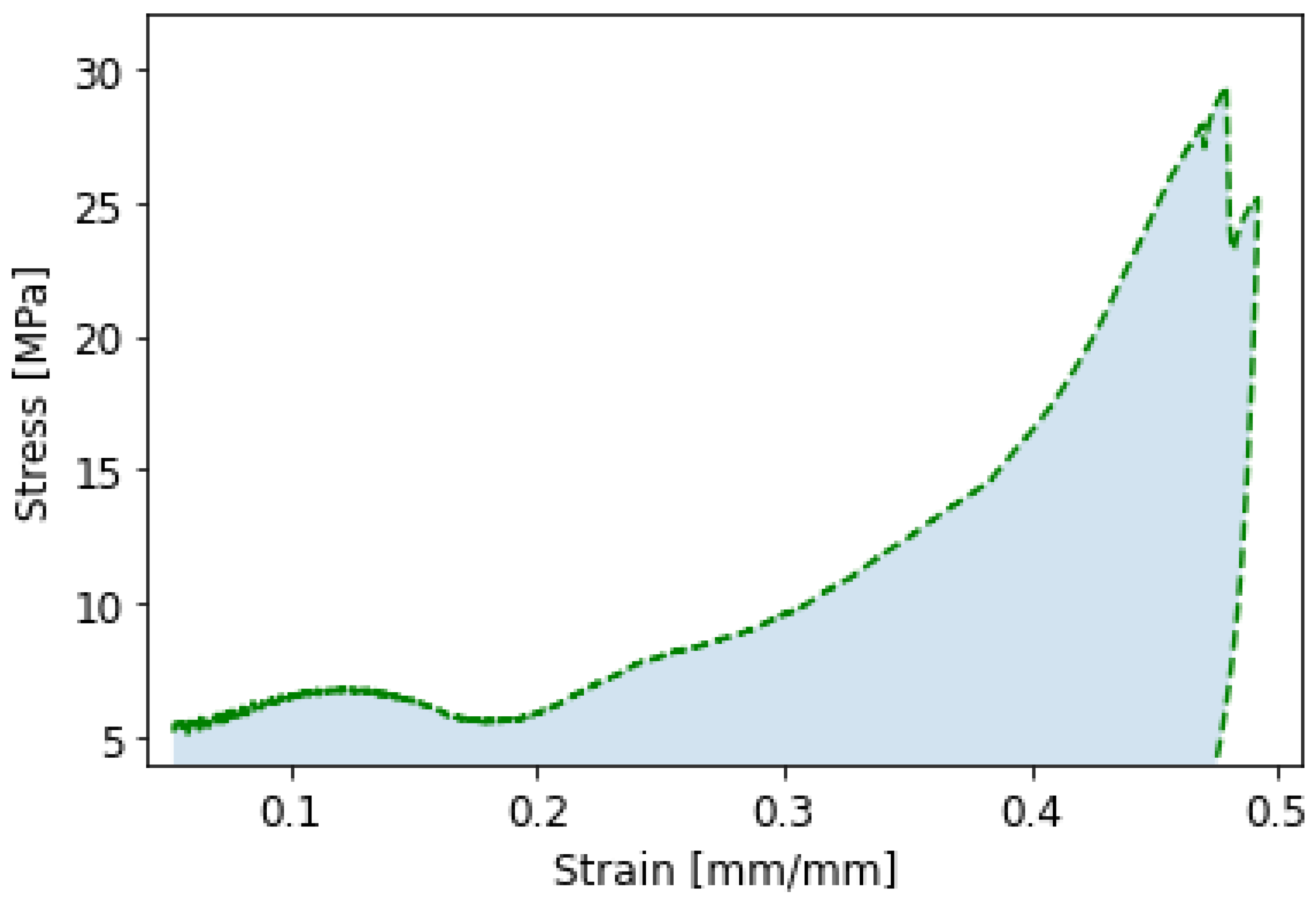
where β is the strain constraint factor. Figure 6 shows the effective stress-strain curve obtained from Equations (10) and (14).

3.3. Fundamental Assumptions

In the simulation of the LIB cell under the indentation test, it is assumed that the conservation of mass, the balance of momentum, the balance of moment of momentum, and the balance of energy and entropy production hold. The first assumption states that the free energy function was modelled as a scalar function of the tensorial argument [58]:
Ψ = Ψ F ,   M ; μ
where F is the deformation gradient, M denotes the structural tensor (symmetric and positive definite), and μ represents a set of internal state variables, which consists of the damage variable ϕ . Hence, the degradation of mechanical properties of the LIB cell is described using a single scalar damage parameter, as follows:
μ = ϕ
As usual in damage mechanics, the variable ϕ takes the value within limits 0 , 1 . Moreover, it should be noted that the damage variable has a phenomenological meaning, so that ϕ = 0 is equivalent to the undamaged material, and ϕ = 1 means the complete loss of load-carrying capacity (loss of continuity). Next, one can rewrite the free energy function Equation (16) as:
Ψ = Ψ F ,   M ; μ = 1 ϕ Ψ ˜ F , M
where Ψ ˜ F , M is the effective (undamaged) Helmholtz free-energy function. Furthermore, based on LIB geometry and its internal structure, we assume that anisotropic behavior is of transverse isotropic type [58], therefore:
Ψ ˜ = Ψ ti ˜ = Ψ ti ^ I 1 , I 2 , I 3 , J 4 , J 5 = Ψ iso I 1 , I 2 , I 3 + Ψ ti J 4 , J 5
where
I 1 = tr C , I 2 = tr Cof C , I 3 = det C , J 4 = tr C M , J 5 = tr Cof C M
where Ψ iso stands for the isotropic part, Ψ ti stands for transverse isotropy term, C denotes the right Cauchy-Green tensor, Cof C = det C C 1 and M = diag a , a , b ( X 3 spatial direction as chosen as a preferred one—axonal structure direction).
Under the above assumptions, the constitutive relation for the HTFD model is, in general
S = 2 1 ϕ Ψ ti ˜ I 1 + Ψ ti ˜ I 2 I 1 1 Ψ ti ˜ I 2 C + Ψ ti ˜ I 3 I 3 + Ψ ti ˜ J 5 J 5 C 1 + Ψ ti ˜ J 4 M Ψ ti ˜ J 5 I 3 C 1 M C 1
where S denotes the 2nd Piola-Kirchhoff stress tensor, an explicit definition of S requires a specific form of the effective (undamaged) Helmholtz free-energy function, and the meaning of damage evolution—experimental data inspire both [59].

3.4. Free-Energy Function and Damage Evolution

Based on experimental evidence, the isotropic part of the effective (undamaged) Helmholtz free-energy function is assumed to be governed by the compressible Mooney- Rivlin model, namely
Ψ iso I 1 ,   I 2 ,   I 3 =   α 1 I 1 + α 2 I 2 + δ 1 I 3 δ 2 ln I 3
where α 1 , α 2 , δ 1 , δ 2 0 denotes material parameters. Next, the transverse isotropic term has the form proposed by Schroder et al., (2008)
Ψ ti = 1 α 4 trM α 4 η 1 J 4 α 4 + J 45 α 4
where M = diag γ 1 2 , 1 γ 1 , 1 γ 1 ,   and   γ 1 , η 1 0 and α 4 1 are material parameters. Furthermore, to fulfill the stress-free initial configuration, the above material parameters should satisfy the requirement
δ 2 = 2 α 1 + 4 α 2 + 2 δ 1 + 2 η 1
The above assumptions allow one to rewrite the constitutive relation to the form
S = 2 1 ϕ α 1 + α 2 I 1 1 α 2 C + δ 1 I 3 δ 2 2 + η 1 trM α 4 J 5 α 4 C 1 + η 1 trM α 4 J 4 α 4 1 M η 1 trM α 4 J 5 α 4 1 I 3 C 1 M C 1
As mentioned, the Caput-Almeida fractional derivative is used to describe the evolution of damage in time, which simultaneously introduces memory to the general constitutive law. One has then the following form for damage evolution
D t α , Ψ t l t C ϕ = 1 T Φ I ϕ τ ϕ 1
where D t α , Ψ t l t C denotes the Caputo-Almeida fractional derivative operator (Almeida, 2017)
D t α , Ψ t l t C f t = 1 Γ n α t l t t   Ψ τ Ψ t Ψ τ n α 1 1   Ψ t d dt n f t d τ
where α denotes the order of fractional velocity of damage, l t is the time-length scale, Ψ t C n t l t , t is an increasing function that fulfills the requirement Ψ t 0 , n = α + 1 and n = α for α N , T is the characteristic time, defines power which depends on the selected Ψ t , Φ is the overstress function, I ϕ is the stress intensity invariant, τ ϕ is the static threshold stress for damage evolution, and the bracket defines the ramp function. It is vital to notice that the classical damage mechanical model (without memory effects) is a particular case of the proposed evolution law and is obtained for Ψ t = t and α = 1 .
Finally, based on results obtained by Voyiadjis and Sumelka [58]
Φ I ϕ τ ϕ 1 = 1 ϕ I ϕ ˜ τ ϕ n 1 1 n 2
where n 1 , n 2 are material parameters, and
I ϕ ˜ = b a + Ψ ¯ c n + 1 k = 0 n n + k k 2 n + 1 n k Ψ ¯ c k + f exp d Ψ ¯ e
In above equation a , b , c , d , e , f , n are material parameters, Ψ ¯ = I ϕ ¯ C , M I ϕ 0 ¯ , I ϕ 0 ¯ =   I ϕ ¯ C , M | C = 0 , and
I ϕ ¯ = α 1 I 1 + α 2 I 2 + δ 1 I 3 δ 2 ln I 3 + 1 α 4 trM α 4 η 1 J 4 α 4 + J 5 α 4
The material parameters are such that α 1 , α 2 , δ 1 , δ 2 , η 1 0 , α 4 1 , and δ 2 = 2 α 1 + 4 α 2 + 2 δ 1 + 2 η 1 . Altogether we have 23 material parameters:
4 defining anisotropic hyperelastic part α 1 , α 2 , δ 1 , α 4 , η 1
19 defining damage evolution α , l t , T , n 1 , n 2 , τ ϕ , α 1 , α 2 , δ 1 , α 4 , η 1 , a , b , c , d , e ,   f , n plus the modulation function Ψ .
For model validation, the number of material parameters is initially reduced to 17 under the assumption that α 1 = α 1 , α 2 = α 2 , δ 1 = δ 1 , α 4 = α 4 , η 1 = η 1 , and that full-memory assumption holds, therefore l t could be reduced as well.

3.5. Model Validation

The hyperelastic time-fractional damage (HTFD) model has been implemented in the Mathematica software and identified based on experimental evidence on the LIB specimen. Calibration has been prepared under the assumption of best fitting curve utilizing an optimization task (FindFit function from the Mathematica software [60], utilizing “Quasi Newton” optimization, i.e., the quasi-Newton BFGS approximation to the Hessian was applied) for selected modulation functions Ψ . The best results were obtained for Ψ t = t 3 + 1 , therefore, in consequence in damage evolution law = 3 α . Material parameters are collected in Table 1, whereas the comparison of experimental data with HTFD model predictions is presented in Figure 7.
Figure 7 presents the stretch ( λ 1 ) vs. stress ( P 11 1st Piola-Kirchhoff stress component) for 3 cases: experimental data, undamaged answer (purely elastic case; τ ϕ ), and full-range HTFD model prediction. Since the main novelty of the proposed description is the application of fractional calculus for the definition of internal state variable evolution, one should notice that the fractional-velocity of damage of order α = 0.72 (with the physical dimension s 3 0.72 ) provided the best approximation of experimental data. One can observe that the first stage of softening appears for λ 1 1.08 and rapidly grows up to λ 1 1.18 . In the next step, damage grows slowly and at the limit λ 1 1.48 jumps drastically up to its extreme value ϕ 1 .
Finally, it is clear that the HTFD model provides proper predictions in the phenomenological sense. Complex damage phenomena in real specimens can be correctly described in a homogenized sense through a single scalar variable whose evolution follows a time-factional velocity curve. One should point out that such flexibility is obtained through one parameter ( α ) and a single modulation function ( Ψ ), compared to the classical damage mechanics approach.

4. Conclusions

The indentation test was performed using the cylindrical indenter. This research addresses the difficulty of converting force depth data into engineering stress-strain relations. Measuring the projected contact area between two cylinders is one of the issues posed by this mechanical test, which this study addresses by proposing a few analytical approaches and the FEM model. However, another innovation of this research is a multistep indentation test that was performed to measure the reduction of Young’s modulus. In contrast to previously published models, which can predict elastoplastic behavior but cannot predict LIB cell damage, an analytical damage model has been developed in this work. Hence, a definition is provided for an anisotropic hyperelastic theory that accounts for fractional scalar damage development regulated by the Caputo-Almeida fractional derivative. The refined damage model is then implemented for the constrained indentation configuration of the experiment. This study demonstrates that the numerical findings qualitatively and quantitatively closely match the experimental data.

Author Contributions

G.Z.V. and W.S. Towards: Review and editing; E.A.: Writing—reviewing and editing, visualization, simulation, experiment, Analytical; B.Ł.: Analytical. All authors have read and agreed to the published version of the manuscript.

Funding

This research received no external funding.

Informed Consent Statement

Informed consent was obtained from all subjects involved in the study.

Data Availability Statement

The data presented in this study are available on request from the corresponding author. The data are not publicly available due to long-time experiment and rich information.

Conflicts of Interest

The authors declare no conflict of interest.

References

  1. Masias, A.; Felten, N.; Sakamoto, J. Characterizing the mechanical behavior of lithium in compression. J. Mater. Res. 2021, 36, 729–739. [Google Scholar] [CrossRef]
  2. Kermani, G.; Keshavarzi, M.M.; Sahraei, E. Deformation of lithium-ion batteries under axial loading: Analytical model and Representative Volume Element. Energy Rep. 2021, 7, 2849–2861. [Google Scholar] [CrossRef]
  3. Spielbauer, M.; Berg, P.; Soellner, J.; Peters, J.; Schaeufl, F.; Rosenmüller, C.; Bohlen, O.; Jossen, A. Experimental investigation of the failure mechanism of 18650 lithium-ion batteries due to shock and drop. J. Energy Storage 2021, 43, 103213. [Google Scholar] [CrossRef]
  4. Zhu, F.; Zhou, R.; Sypeck, D.J. Numerical modeling and safety design for lithium-ion vehicle battery modules subject to crush loading. Energies 2020, 14, 118. [Google Scholar] [CrossRef]
  5. Kisters, T.; Sahraei, E.; Wierzbicki, T. Dynamic impact tests on lithium-ion cells. Int. J. Impact Eng. 2017, 108, 205–216. [Google Scholar] [CrossRef]
  6. Luo, H.; Xia, Y.; Zhou, Q. Mechanical damage in a lithium-ion pouch cell under indentation loads. J. Power Source 2017, 357, 61–70. [Google Scholar] [CrossRef]
  7. Keshavarzi, M.M.; Gilaki, M.; Sahraei, E. Characterization of in-situ material properties of pouch lithium-ion batteries in tension from three-point bending tests. Int. J. Mech. Sci. 2022, 219, 107090. [Google Scholar] [CrossRef]
  8. Zhu, X.; Wang, H.; Wang, X.; Gao, Y.; Allu, S.; Cakmak, E.; Wang, Z. Internal short circuit and failure mechanisms of lithium-ion pouch cells under mechanical indentation abuse conditions: An experimental study. J. Power Source 2020, 455, 227939. [Google Scholar] [CrossRef]
  9. Lian, J.; Koch, M.; Li, W.; Wierzbicki, T.; Zhu, J. Mechanical deformation of Lithium-ion pouch cells under in-plane loads—Part II: Computational modeling. J. Electrochem. Soc. 2020, 167, 090556. [Google Scholar] [CrossRef]
  10. Gao, Z.; Zhang, X.; Xiao, Y.; Gao, H.; Wang, H.; Piao, C. Influence of low-temperature charge on the mechanical integrity behavior of 18650 lithium-ion battery cells subject to lateral compression. Energies 2019, 12, 797. [Google Scholar] [CrossRef]
  11. Ren, F.; Cox, T.; Wang, H. Thermal runaway risk evaluation of Li-ion cells using a pinch–torsion test. J. Power Source 2014, 249, 156–162. [Google Scholar] [CrossRef]
  12. Ellersdorfer, C.; Höschele, P.; Heider, E.; Kovachev, G.; Gstrein, G. Safety Assessment of High Dynamic Pre-Loaded Lithium Ion Pouch Cells. Batteries 2023, 9, 71. [Google Scholar] [CrossRef]
  13. Gilaki, M.; Song, Y.; Sahraei, E. Homogenized characterization of cylindrical Li-ion battery cells using elliptical approximation. Int. J. Energy Res. 2022, 46, 5908–5923. [Google Scholar] [CrossRef]
  14. Kermani, G.; Dixon, B.; Sahraei, E. Elliptical lithium-ion batteries: Transverse and axial loadings under wet/dry conditions. Energy Sci. Eng. 2019, 7, 890–898. [Google Scholar] [CrossRef]
  15. Aphale, S.; Murugkar, M.; Lulla, S.; Date, P. Deformation and Failure Behavior of Cylindrical Lithium-Ion Batteries Subjected to Mechanical Loading; SAE Technical Paper: Warrendale, PA, USA, 2020; pp. 0148–7191. [Google Scholar]
  16. Avdeev, I.; Gilaki, M. Structural analysis and experimental characterization of cylindrical lithium-ion battery cells subject to lateral impact. J. Power Source 2014, 271, 382–391. [Google Scholar] [CrossRef]
  17. Raffler, M.; Sevarin, A.; Ellersdorfer, C.; Heindl, S.F.; Breitfuss, C.; Sinz, W. Finite element model approach of a cylindrical lithium ion battery cell with a focus on minimization of the computational effort and short circuit prediction. J. Power Source 2017, 360, 605–617. [Google Scholar] [CrossRef]
  18. Sheikh, M.; Elmarakbi, A.; Elkady, M. Thermal runaway detection of cylindrical 18650 lithium-ion battery under quasi-static loading conditions. J. Power Source 2017, 370, 61–70. [Google Scholar] [CrossRef]
  19. Chung, S.H.; Tancogne-Dejean, T.; Zhu, J.; Luo, H.; Wierzbicki, T. Failure in lithium-ion batteries under transverse indentation loading. J. Power Source 2018, 389, 148–159. [Google Scholar] [CrossRef]
  20. Muresanu, A.D.; Dudescu, M.C. Numerical and Experimental Evaluation of a Battery Cell under Impact Load. Batteries 2022, 8, 48. [Google Scholar] [CrossRef]
  21. Zhu, F.; Zhou, R.; Sypeck, D.; Deng, J.; Bae, C. Failure behavior of prismatic Li-ion battery cells under abuse loading condition-A combined experimental and computational study. J. Energy Storage 2022, 48, 103969. [Google Scholar] [CrossRef]
  22. Li, W.; Xing, B.; Watkins, T.R.; Xia, Y.; Wang, H.; Zhu, J. Damage of prismatic lithium-ion cells subject to bending: Test, model, and detection. EcoMat 2022, 4, e12257. [Google Scholar] [CrossRef]
  23. Wang, H.; Simunovic, S.; Maleki, H.; Howard, J.N.; Hallmark, J.A. Internal configuration of prismatic lithium-ion cells at the onset of mechanically induced short circuit. J. Power Source 2016, 306, 424–430. [Google Scholar] [CrossRef]
  24. Lamb, J.; Orendorff, C.J. Evaluation of mechanical abuse techniques in lithium ion batteries. J. Power Source 2014, 247, 189–196. [Google Scholar] [CrossRef]
  25. Mao, B.; Chen, H.; Cui, Z.; Wu, T.; Wang, Q. Failure mechanism of the lithium ion battery during nail penetration. Int. J. Heat Mass Transf. 2018, 122, 1103–1115. [Google Scholar] [CrossRef]
  26. Feng, X.; Sun, J.; Ouyang, M.; Wang, F.; He, X.; Lu, L.; Peng, H. Characterization of penetration induced thermal runaway propagation process within a large format lithium ion battery module. J. Power Source 2015, 275, 261–273. [Google Scholar] [CrossRef]
  27. Ma, T.; Chen, L.; Liu, S.; Zhang, Z.; Xiao, S.; Fan, B.; Liu, L.; Lin, C.; Ren, S.; Wang, F. Mechanics-morphologic coupling studies of commercialized lithium-ion batteries under nail penetration test. J. Power Source 2019, 437, 226928. [Google Scholar] [CrossRef]
  28. Aiello, L.; Gstrein, G.; Erker, S.; Kaltenegger, B.; Ellersdorfer, C.; Sinz, W. Optimized Nail for Penetration Test on Lithium-Ion Cells and Its Utilization for the Validation of a Multilayer Electro-Thermal Model. Batteries 2022, 8, 32. [Google Scholar] [CrossRef]
  29. Doose, S.; Haselrieder, W.; Kwade, A. Effects of the Nail Geometry and Humidity on the Nail Penetration of High-Energy Density Lithium Ion Batteries. Batteries 2021, 7, 6. [Google Scholar] [CrossRef]
  30. Sahraei, E.; Meier, J.; Wierzbicki, T. Characterizing and modeling mechanical properties and onset of short circuit for three types of lithium-ion pouch cells. J. Power Source 2014, 247, 503–516. [Google Scholar] [CrossRef]
  31. Sahraei, E.; Campbell, J.; Wierzbicki, T. Modeling and short circuit detection of 18650 Li-ion cells under mechanical abuse conditions. J. Power Source 2012, 220, 360–372. [Google Scholar] [CrossRef]
  32. Sahraei, E.; Kahn, M.; Meier, J.; Wierzbicki, T. Modelling of cracks developed in lithium-ion cells under mechanical loading. RSC Adv. 2015, 5, 80369–80380. [Google Scholar] [CrossRef]
  33. Wang, W.; Yang, S.; Lin, C. Clay-like mechanical properties for the jellyroll of cylindrical Lithium-ion cells. Appl. Energy 2017, 196, 249–258. [Google Scholar] [CrossRef]
  34. Cai, W.; Wang, H.; Maleki, H.; Howard, J.; Lara-Curzio, E. Experimental simulation of internal short circuit in Li-ion and Li-ion-polymer cells. J. Power Source 2011, 196, 7779–7783. [Google Scholar] [CrossRef]
  35. Sahraei, E.; Hill, R.; Wierzbicki, T. Calibration and finite element simulation of pouch lithium-ion batteries for mechanical integrity. J. Power Source 2012, 201, 307–321. [Google Scholar] [CrossRef]
  36. Greve, L.; Fehrenbach, C. Mechanical testing and macro-mechanical finite element simulation of the deformation, fracture, and short circuit initiation of cylindrical Lithium ion battery cells. J. Power Source 2012, 214, 377–385. [Google Scholar] [CrossRef]
  37. Wang, Q.; Mao, B.; Stoliarov, S.I.; Sun, J. A review of lithium ion battery failure mechanisms and fire prevention strategies. Prog. Energy Combust. Sci. 2019, 73, 95–131. [Google Scholar] [CrossRef]
  38. Xu, J.; Liu, B.; Hu, D. State of Charge Dependent Mechanical Integrity Behavior of 18650 Lithium-ion Batteries. Sci. Rep. 2016, 6, 21829. [Google Scholar] [CrossRef] [PubMed]
  39. Zhu, J.; Zhang, X.; Sahraei, E.; Wierzbicki, T. Deformation and failure mechanisms of 18650 battery cells under axial compression. J. Power Source 2016, 336, 332–340. [Google Scholar] [CrossRef]
  40. Song, Y.; Gilaki, M.; Keshavarzi, M.M.; Sahraei, E. A universal anisotropic model for a lithium-ion cylindrical cell validated under axial, lateral, and bending loads. Energy Sci. Eng. 2022, 10, 1431–1448. [Google Scholar] [CrossRef]
  41. Wierzbicki, T.; Sahraei, E. Homogenized mechanical properties for the jellyroll of cylindrical Lithium-ion cells. J. Power Source 2013, 241, 467–476. [Google Scholar] [CrossRef]
  42. Wang, L.; Yin, S.; Xu, J. A detailed computational model for cylindrical lithium-ion batteries under mechanical loading: From cell deformation to short-circuit onset. J. Power Source 2019, 413, 284–292. [Google Scholar] [CrossRef]
  43. Zhu, J.; Li, W.; Wierzbicki, T.; Xia, Y.; Harding, J. Deformation and failure of lithium-ion batteries treated as a discrete layered structure. Int. J. Plast. 2019, 121, 293–311. [Google Scholar] [CrossRef]
  44. Li, W.; Zhu, J. A Large Deformation and Fracture Model of Lithium-Ion Battery Cells Treated as a Homogenized Medium. J. Electrochem. Soc. 2020, 167, 120504. [Google Scholar] [CrossRef]
  45. Voyiadjis, G.Z.; Akbari, E.; Kattan, P.I. Damage model for lithium-ion batteries with experiments and simulations. J. Energy Storage 2023, 57, 106285. [Google Scholar] [CrossRef]
  46. Ali, M.Y.; Lai, W.-J.; Pan, J. Computational models for simulation of a lithium-ion battery module specimen under punch indentation. J. Power Source 2015, 273, 448–459. [Google Scholar] [CrossRef]
  47. Lai, W.-J.; Ali, M.Y.; Pan, J. Mechanical behavior of representative volume elements of lithium-ion battery modules under various loading conditions. J. Power Source 2014, 248, 789–808. [Google Scholar] [CrossRef]
  48. Murakami, S. Continuum Damage Mechanics: A Continuum Mechanics Approach to the Analysis of Damage and Fracture; Springer Science & Business Media: Berlin/Heidelberg, Germany, 2012; Volume 185. [Google Scholar]
  49. Chow, C.; Wang, J. An anisotropic theory of continuum damage mechanics for ductile fracture. Eng. Fract. Mech. 1987, 27, 547–558. [Google Scholar] [CrossRef]
  50. Perzyna, P. The constitutive equations for rate sensitive plastic materials. Q. Appl. Math. 1963, 20, 321–332. [Google Scholar] [CrossRef]
  51. Almeida, R. A Caputo fractional derivative of a function with respect to another function. Commun. Nonlinear Sci. Numer. Simul. 2017, 44, 460–481. [Google Scholar] [CrossRef]
  52. Hertz, H. Miscellaneous Papers; Macmillan: Stuttgart, Germany, 1896. [Google Scholar]
  53. Wang, H.; Duan, X.; Liu, B. The Anisotropic Homogenized Model for Pouch Type Lithium-Ion Battery Under Various Abuse Loadings. J. Electrochem. Energy Convers. Storage 2021, 18, 021015. [Google Scholar] [CrossRef]
  54. Popov, V.L. Contact Mechanics and Friction; Springer: Berlin/Heidelberg, Germany, 2010. [Google Scholar]
  55. Yang, S.; Wang, W.; Lin, C.; Shen, W.; Li, Y. Improved constitutive model of the jellyroll for cylindrical lithium ion batteries considering microscopic damage. Energy 2019, 185, 202–212. [Google Scholar] [CrossRef]
  56. Xu, B.; Chen, X. Determining engineering stress–strain curve directly from the load–depth curve of spherical indentation test. J. Mater. Res. 2010, 25, 2297–2307. [Google Scholar] [CrossRef]
  57. Kalidindi, S.R.; Pathak, S. Determination of the effective zero-point and the extraction of spherical nanoindentation stress–strain curves. Acta Mater. 2008, 56, 3523–3532. [Google Scholar] [CrossRef]
  58. Voyiadjis, G.Z.; Sumelka, W. Brain modelling in the framework of anisotropic hyperelasticity with time fractional damage evolution governed by the Caputo-Almeida fractional derivative. J. Mech. Behav. Biomed. Mater. 2019, 89, 209–216. [Google Scholar] [CrossRef] [PubMed]
  59. Sumelka, W.; Łuczak, B.; Gajewski, T.; Voyiadjis, G.Z. Modelling of AAA in the framework of time-fractional damage hyperelasticity. Int. J. Solids Struct. 2020, 206, 30–42. [Google Scholar] [CrossRef]
  60. FindFit. Available online: https://reference.wolfram.com/language/ref/FindFit.html (accessed on 20 March 2023).
Figure 1. Experimental setup of indentation of a cylindrical LIB cell with a cylindrical indenter.
Batteries 09 00233 g001
Figure 2. Five single-loading indentation tests at five different penetration depths (a), unloading segments (b), and degradation of Young’s modulus (c).
Batteries 09 00233 g002
Figure 3. (a) Deformed LIB cell through the indentation test, (b) Schematic of a cylindrical LIB cell being indented by a rigid cylindrical indenter, (c) Graphical representation of fitting an ellipsoidal cap to the deformed surface.
Batteries 09 00233 g003
Figure 4. Comparison between the calculated contact area from the analytical and FE model.
Batteries 09 00233 g004
Figure 5. Measured indentation load–depth data.
Batteries 09 00233 g005
Figure 6. The effective stress-strain curve.
Batteries 09 00233 g006
Figure 7. Comparison of experimental data (orange line) with HTFD model predictions (blue line) is contrasted with purely elastic (undamaged; τ ϕ ) case (green line).
Batteries 09 00233 g007
Table 1. HTFD material parameters for LIB.
α 1 = α 1 = 10.50   MPa T = 0.257   s c = 1.72 MPa
α 2 = α 2 = 7.60   MPa n 1 = 1.76 d = 9.78 MPa 1
δ 1 = δ 1 = 7.00   MPa n 2 = 1.83   e = 15.29 MPa
α 4 = α 4 = 18.9   τ ϕ = 0.55   MPa f = 1.01 MPa
η 1 = η 1 = 1.90 MPa a = 0.55 n = 2
α = 0.72   b = 1.01 MPa
Disclaimer/Publisher’s Note: The statements, opinions and data contained in all publications are solely those of the individual author(s) and contributor(s) and not of MDPI and/or the editor(s). MDPI and/or the editor(s) disclaim responsibility for any injury to people or property resulting from any ideas, methods, instructions or products referred to in the content.