Article

Effect of Si Content on Extreme Fast Charging Behavior in Silicon–Graphite Composite Anodes

Chemical Sciences and Engineering Division, Argonne National Laboratory, 9700 South Cass Avenue, Lemont, IL 60439, USA
*
Author to whom correspondence should be addressed.
Batteries 2023, 9(2), 138; https://doi.org/10.3390/batteries9020138
Submission received: 13 January 2023 / Revised: 8 February 2023 / Accepted: 13 February 2023 / Published: 16 February 2023
(This article belongs to the Special Issue Lithium-Ion Batteries and Beyond: Outlook on Present and Future)

Abstract

:
Commercial Li-ion batteries typically incorporate a small amount of high-capacity silicon (Si)-based materials in the composite graphite-based anode to increase the energy density of the battery. However, very little is known about the effects of Si on the fast-charging behavior of composite anodes. Herein, we examine the effects of the Si/graphite ratio in the composite anode on the fast-charging behavior of full cells. We show that addition of Si increases the rate capability from 1C to 8C and improves the capacity retention in early cycles at 6C due to reduced overpotential in constant current charging cycles. The impacts of Si content on fast-charging aging were identified by Post-Test characterization. Despite realizing benefits of available capacity and reduced Li plating at 6C, silicon–electrolyte interactions lead the time-dependent cell performance to fade quickly in the long term. The Post-Test analysis also revealed the thickening of the electrode and nonuniform distribution of electrolyte decomposition products on the Si-containing anodes, as well as the organic-rich solid electrolyte interphase (SEI), which are the factors behind cell degradation. Our study sheds insight on the advantages and disadvantages of Si/graphite composite anodes when they are used in fast-charging applications and guides further research in the area by designing an optimized composition of Si incorporated in a mature graphite matrix.

1. Introduction

In the last few years, there has been a sharp growth in demand for the creation of fast-charging capabilities for electric vehicles (EVs) powered by Li-ion batteries. Due to their limited driving ranges, the consumer preference for a rapid charging (<2 h) capability is driving cars with the EV battery design; therefore, presenting future EVs to the market requires extreme fast charging (XFC) at rates between 4.8 and 6 C, which can restock 80% of the pack capacity from 12.5 to 10 min. In addition to the high performance expectations of established battery technologies, faster charging poses difficulties for today’s batteries due to rapid battery aging and safety issues such lithium plating [1], the loss of active material particles [2], and impedance growth [2].
The negative electrode, a predominately graphite-based (Gr) material in current lithium-ion batteries (LIBs), is considered to be the component limiting the control of how quickly the battery can be charged during XFC [3,4]. Silicon (Si) is a promising alternative anode materials for LIBs due to its high theoretical gravimetric capacity (3579 mAh g−1 for Li15Si4) relative to that of commercial graphite anodes (372 mAh g−1 for LiC6) [5]. The higher lithium-alloying potential of Si (0.22 V vs. Li/Li+) relative to a low discharge potential of Gr (0.08 V vs. Li/Li+) can mitigate Li plating, which is particularly important for fast charging [6,7]. Commercializing silicon anodes particularly for XFC applications is not an easy task due to significant limitations including their poor electrical conductivity, high volume expansion, cracking and pulverization, and unstable solid–electrolyte interface (SEI) [5,8]. Structural design strategies can increase the stability of the silicon anode and partially mitigate the challenges stated above. For example, Si nanostructures, such as nanotubes [9], nanoparticles [10], nanowires [11], and core–shell structure [5] proved to be effective at achieving the enhanced transfer of lithium, an improved cycle life, and enabled free space volume to accommodate the volume expansion and reduce the material stress during lithiation [12]. Despite their benefits, nanostructure designs present challenges to XFC operation. They are susceptible to increased side reactions with electrolytes and charge transfer resistance due to high surface areas. Additionally, the cost and complexity currently hinder the cost-effective implementation of nanostructural silicon in industrial manufacturing processes.
A practical solution is to develop silicon in graphite matrix composite anodes, taking advantage of graphite’s low surface area, electrical conductivity, and stability and silicon’s high capacity. Indeed, the co-utilization of Si-Gr in composite anodes is reported to meet capacity and cycling stability requirements, as well as cost-effective, large-scale industrial production [13,14]. Relative to graphite electrodes, however, they represent unique degradation processes. For example, Ruther et al. identified that composite anodes are heterogeneous with separated graphite-rich and silicon-rich phase regions with lithiation by Raman mapping [15]. Kirkaldy et al. found that the loss of active silicon in Si-Gr composites is the major cell fading factor under operating conditions [16]. More recently, Lee et al. reported that the self-discharge rate increases preferentially in Si by interfacial side reactions and results in electron energy imbalance between Si and Gr in the composite anode [17]. These reports mostly focused on the evaluation of cell performance and the identification of degradation mechanisms with Si-Gr anodes under mild cycling conditions. Si-containing electrodes designed and used to attain fast-charging characteristics further aggravate the typical degradation mechanisms. Mechanistic insights for the aging behavior of composite anodes under XFC cycling conditions is needed to understand the aging effect, predict and mitigate degradation, and improve cell performance [18,19,20]. Hence, a thorough understanding of the obstacles of fast charging is essential to reveal the aging mechanisms of Si-Gr composites and develop strategies to reduce degradation and produce XFC technologies containing Si-based anodes.
In this work, we provide a systematic investigation of the effect of Si on fast charging and degradation mechanisms contributing to the capacity fade in the composite anodes. For this purpose, we evaluated the performance of the electrodes’ containing various Si and Gr concentrations in full cells versus that of NMC811 under XFC conditions. Since carbon additives and binders also play significant role in the conductivity, interphase chemistry, and mechanical integration of the Si-Gr composites, as reported [21], we maintained a constant ratio of carbon additives and binders to active material in this study. We present the impact of XFC charge protocols at charging rates of 1C-8C and long-term aging at 6C. We couple cell performance to the evolution of the bulk electrode structure and interface, including morphology and compositional changes by Scanning Electron Microscopy (SEM/EDS) and SEI composition by X-ray Photoelectron Spectroscopy (XPS). The analysis of these relations provides clarity on the relative benefits of Si in XFC cells and the trade-off between a greater capacity and a shorter lifetime. Our findings of the Si-Gr interfacial structure provide further predictive control of the Si interface chemistry through surface modifiers, such as electrolyte additives or coatings, which are critical for next-generation cell discovery and design.

2. Materials and Methods

Materials. In this work, all of the electrode laminates used were provided by the Cell Analysis, Modeling, and Prototyping (CAMP) Facility at Argonne National Laboratory. The compositions and properties of the NMC811 positive electrode and the Si-Gr negative electrode with different Si contents are given in Table 1. For a fair comparison, the amounts of binder and carbon additive were the same for all three composite anodes, and only the Si and Gr contents changed. The NMC811 electrode were cut into 14 mm dia disks, and the negative laminate was cut into 15 mm dia disks. The disks were dried in active vacuum oven in the glovebox at 110 °C overnight for NMC811 and at 140 °C for Si-Gr anodes prior to cell assembly. Sixteen mm dia disks of Celgard 2320 separator sheet were used in the coin cells. As the electrolyte in the cell, 1.2 M LiPF6 in ethyl methyl carbonate:ethylene carbonate (7:3 by wt%) with 3 wt% fluoroethylene carbonate (FEC) was used.
Electrochemical testing. With the Si-Gr/NMC811 full cell, rate capability tests were carried out at constant C-rates from 1 to 8C, with a subsequent constant voltage hold of 4.1 V until the current fell below 0.2C. All of the C-rates were calculated based on the measured discharge capacity during the formation process at 0.05C. All of the electrochemical experiments were run on an MACCOR Series 4000 battery cycler in triplicate. The long-term fast-charging aging tests used the following protocol proceeded as such: the cells were first tap charged to 1.5 V, and this was held for 15 min, then left to rest at an open circuit voltage (OCV) for 12 h. Then, the cells were formed at the C/10 rate for 3 cycles, followed by C/1 rate for another 2 cycles, with cutoff voltage between 3.0 and 4.1 V. Since most current commercial fast chargers employ the constant current-constant voltage (CC-CV) charging protocol, it was adopted for the aging analysis in this work. The aging protocol was performed by cycling the cells at C/20 rate for 2 cycles first, and then charging them at 6C (CC-CV with 10 min total time limit) and discharging them at C/2 (CC) for 100 cycles between 3.0 and 4.1 V. Reference performance tests (RPTs) were performed at every 25 intervals, including C/20 CC charge and discharge tests between 3 and 4.1 V.
Scanning Electron Microscopy (SEM). The cells were dissembled, and the electrodes were harvested in the glovebox. The anode materials were rinsed twice with excess dimethyl carbonate (DMC) for 1 min each time. Then, the samples were transferred from glovebox into the SEM column without air exposure using a vacuum-sealable transfer holder that was described in our previous work [22]. SEM/EDS data were collected using a JEOL JSM-6610LV/coupled with an EDS detector (Oxford) at 20 kV.
X-ray Photoelectron Spectroscopy (XPS). XPS measurements on washed electrodes were taken in a Physical Electronics PHI 5000 VersaProbe II system photoelectron spectrometer operating in a high vacuum with typical pressures of under 1 × 10⁻⁷ Torr. The samples were transferred into the XPS analysis chamber through the glovebox without being exposed to ambient air because the apparatus was coupled to the Ar atmosphere glovebox. With 25 W anode power, the Al K X-ray monochromator (hv = 1486.6 eV) was put to use. The charge neutralizer was applied to counterbalance the charging of the sample. The sample surface normal was oriented at 45° to both the X-ray source and photoelectron spectrometer. The elemental high-resolution spectra were collected at pass 23.5 eV of energy through a 100 μm × 100 μm area. The LiF peak at 684.8 eV was used to calibrate the spectra. All of the spectra were processed using Physical Electronics’ Multipack software, which included Shirley background subtraction and curve fitting of multiple Gaussian peaks.

3. Results and Discussion

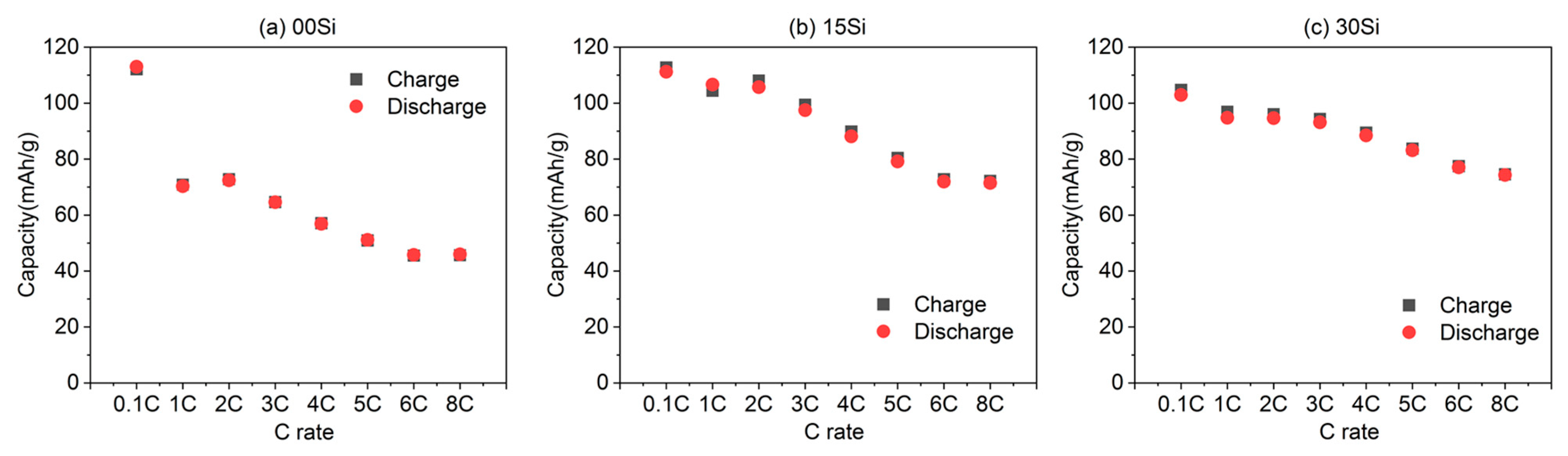
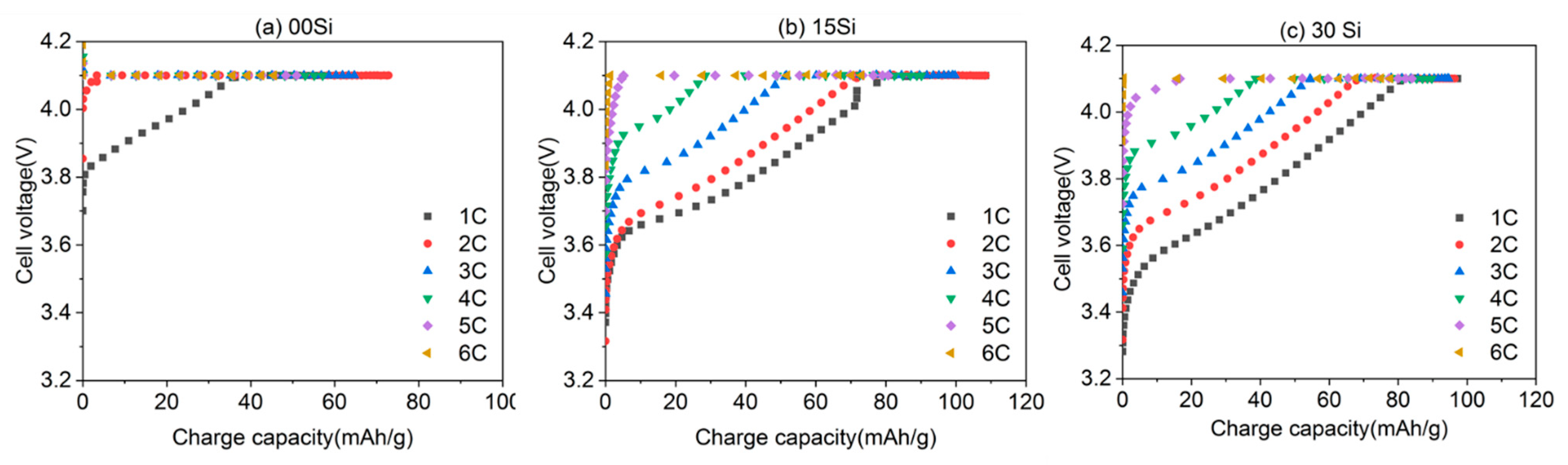
3.1. Electrochemical Performance of Initial Rate Capability Characterization

Cells containing pure Gr anodes (referred to as 00Si), 15 wt% Si (referred to as 15Si), and 30 wt% Si (referred to as 30Si) are compared throughout this paper. To assess the transport constraints for safe cell operation and to assist in protocol development, following two initial 0.05 C forming cycles, rate capability tests between 1C and 8C with four cycles at each rate separated by a C/10 cycle were carried out on a subset of coin cells, as shown in Figure 1a,b. As expected, both the specific discharge and charge declined with an increase in the C-rates up to 6C due to increased polarization, regardless of the anode composition. Between fast charging at 6C and 8C, an insignificant decrease in cell capacity was measured. However, the effect of the Si content on the rate capability can clearly be observed at high currents (Figure 1a). The 30Si cells exhibit better capacity retention as a function of charge rate compared to the dramatic drop observed in the 00Si cells with the increase in the C-rates. The 30Si cell retains ~74% of the capacity at a 6C-rate relative to a C/10 rate, which is in contrast to the capacity retention of the 00Si and 15Si cells (40% and 63%, respectively) at the same rates. As a result, Si addition in the composite brings benefits to the rate capability. Hamzelui et al. also observed an enhanced rate capability as a result of the co-use Si-Gr and appropriate dose optimization of a mixture of polymeric binders (for example, regulating the ratio between LiPAA and CMC with specific compatibility to Si and Gr) [23].
Additionally, during the CC charging, a considerable discrepancy in the high-rate charge acceptance across the three cells is observed. As reported in our previous work, reducing the time and capacity when the cell is close to the upper voltage limit or decreasing the CV portion for Li-ion cells is crucial under XFC to capture high-rate behavior without Li plating [3]. Figure 2 compares the voltage profiles during the charge process for each C-rate and anode composition. For 00Si cells, Vmax (4.1 V) was reached within 10 min at C-rates greater than two. This indicates the charge overpotential increased quickly and constrained the capacity that was reached during the CC charging cycle. In other words, most of the charge capacity was obtained during the 4.1 V CV hold stage for 00Si anodes following applied current densities greater than 2C. In contrast, anodes with Si showed less charge overpotential, leading to approximately 50% of the total charging capacity being achieved during the CC step up to 3C and 4C for 15Si and 30Si, respectively. The potential of Li plating is reduced under CC charging, resulting in a higher capacity. The voltage profiles revealed that Si can facilitate Li+ diffusion in the bulk of the composite anodes, particularly during constant charging process.
Lithium-ion (Li+) insertion/extraction redox reactions, along with contributions from Li+ diffusion across solid-state interphases (SEI and CEI), Li+ diffusion in the bulk of the materials, overpotential, and other factors determine the rate capability of the entire full cell. Heubner et al. reported on an extensive investigation on a “model-like blended Si-Gr electrode,” and found that the silicon’s contribution dominates during lithiation at rates of higher than 2C. This is most likely due to better reaction kinetics in Si [24]. Yao et al. demonstrated in operando X-ray diffraction experiments that silicon addition has a tendency to reduce the overpotential of lithium–graphite phase formation during charging [25]. Thus, our results of the rate capability of the full cells with Si-composite anodes is consistent with previously reported work.

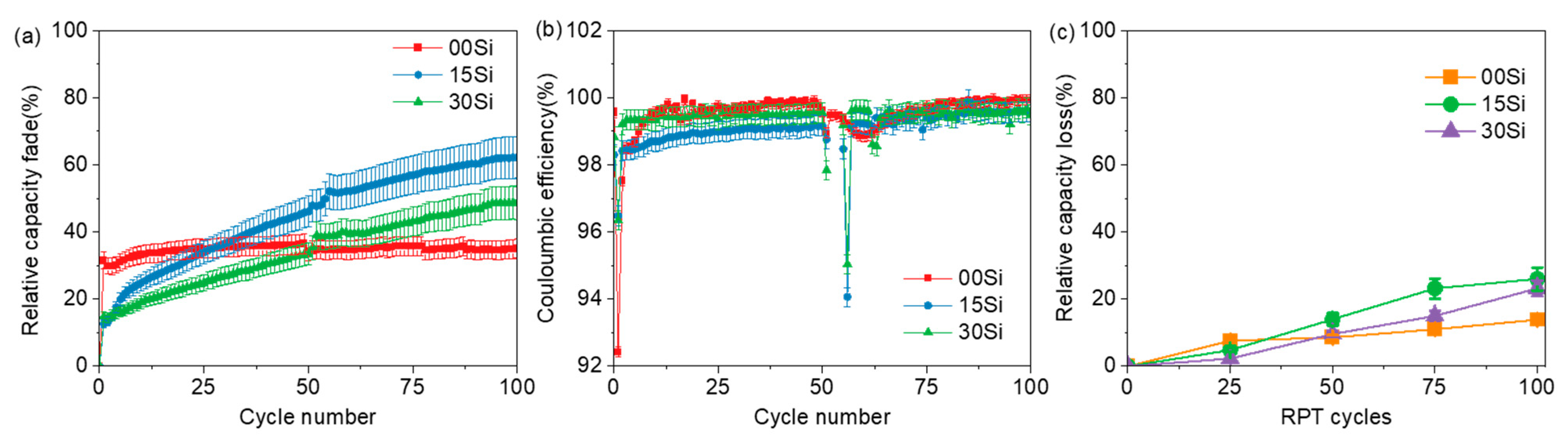
3.2. Electrochemical Performance of Long-Term XFC Aging

To further evaluate the XFC capability performance of Si-Gr-based full cells, more investigations at 6C were conducted for the three anode compositions for the long-term aging analysis. Figure 3 displays the capacity fade and other pertinent cycle life characteristics over 100 cycles using our XFC testing protocols described in the experimental section. Figure 3a shows that the accumulated irreversible capacity fade was higher (~30%) at the very beginning for 00Si, most likely due to significant Li loss from the plating. Then, it showed a distinctly stable and much suppressed decay as the cycling progressed, with lower cell-to-cell variability. In contrast, the rate of the capacity fade in 15Si and 30Si was much lower in the beginning, but they showed a nearly linear increase during later cycles. As a result, both of them showed a higher capacity fade than 00Si did after 100 cycles, indicating that the benefit of adding Si in the Gr matrix is limited to early XFC cycles.
To assess the viability of anode materials, Coulombic efficiency (CE) is a useful metric to designate the rate of deterioration and loss of Li inventory due to side reactions inside a cell. The CEs presented in Figure 3b were calculated using the fast charge and slow discharge (C/2) capacities cycle by cycle during 100 XFC cycles. In Figure 3b, the overall CEs are lower than 100% for all three types of cells, which is usually associated with continuous cyclable Li loss through parasitic reactions on both the anodes and cathodes. Before obtaining efficiencies ~99.9%, the 00Si and 15Si cells exhibited a severe drop in CE during the early cycles (<10 cycles). Tanim et al. and Yang et al. suggested that CE can be utilized in a fast-charging test to signal Li plating as a global electrochemical signature [26]. Thus, the primary cause for such a low CE is attributed to the considerable Li loss due to Li plating in the first ten cycles in addition to the expected SEI formation. In comparison to the 00Si and 15Si, the greater CE values in the 30Si cell suggest significantly less or no Li plating over the first few cycles, which is consistent with what can be seen in Figure 4 in the cell tear-down photographs. In the following cycles, the CE stays relatively steady in 00Si cells, demonstrating less parasitic interactions and, hence, less irreversible active lithium loss as the cycling progresses. A slightly lower CE was still seen throughout subsequent cycles for 15Si and 30Si, which is indicative of continuous SEI development on the anode with the presence of an unstable Si surface.
For XFC cells, it is important to include the Reference Performance Test (RPT) at much slower rate to assess the battery degradation during its testing. Utilization of the electrodes is relatively low under XFC, such that fading at a high C-rate does not necessarily reflect the real degradation behavior and electrode damage that are occurring. Therefore, we performed a discharge capacity test measured at C/20 during RPTs at an interval of 25 every cycles to assess the capacity fading relative to the beginning of life value. As indicated in Figure 3c, the real capacity fade follows the same trend as the XFC conditions. The rate of real capacity fade is higher up to cycle 25, at which point, a marked decrease in fade is apparent during subsequent cycles. Conversely, both of the Si-containing cells exhibit a lower fade in early cycles, but a faster decay afterward. The 30Si cells showed lower fade compared to that of the 15Si up to cycle 75, and then, they overlapped with 15Si after 100 cycles, implying that the Si content indeed affect the cycle life performance in a nonlinear pattern. A higher Si content improves the rate capability for short-term cycling due to its better reaction kinetics with Li+ and reduced overpotential during the charging step, as discussed in Figure 1 and Figure 2. However, its merits were inevitably offset due to continuous parasitic reactions from the enlarged surface area and unstable interface of Si during long-term cycling. Furthermore, the nonlinear correlation between cycle life performance and Si content demonstrate silicon and graphite can interact electrochemically. We cannot rule out other interactions between silicon and graphite besides preferential lithiation, as reported elsewhere [27]. The nature of silicon and graphite electrochemical interactions during CC-CV fast charging and the relative contribution to the overall capacity deserve a future detailed study.

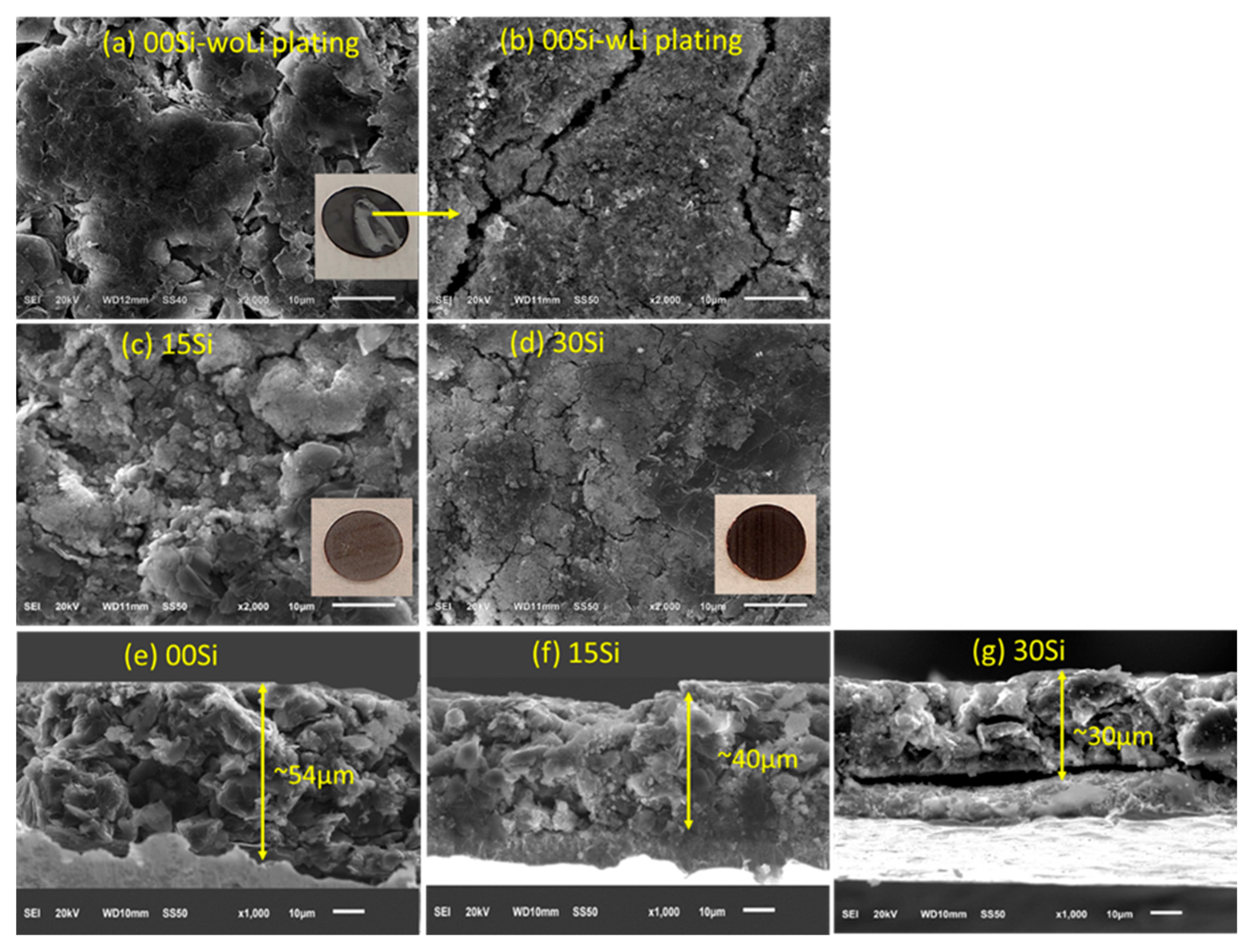
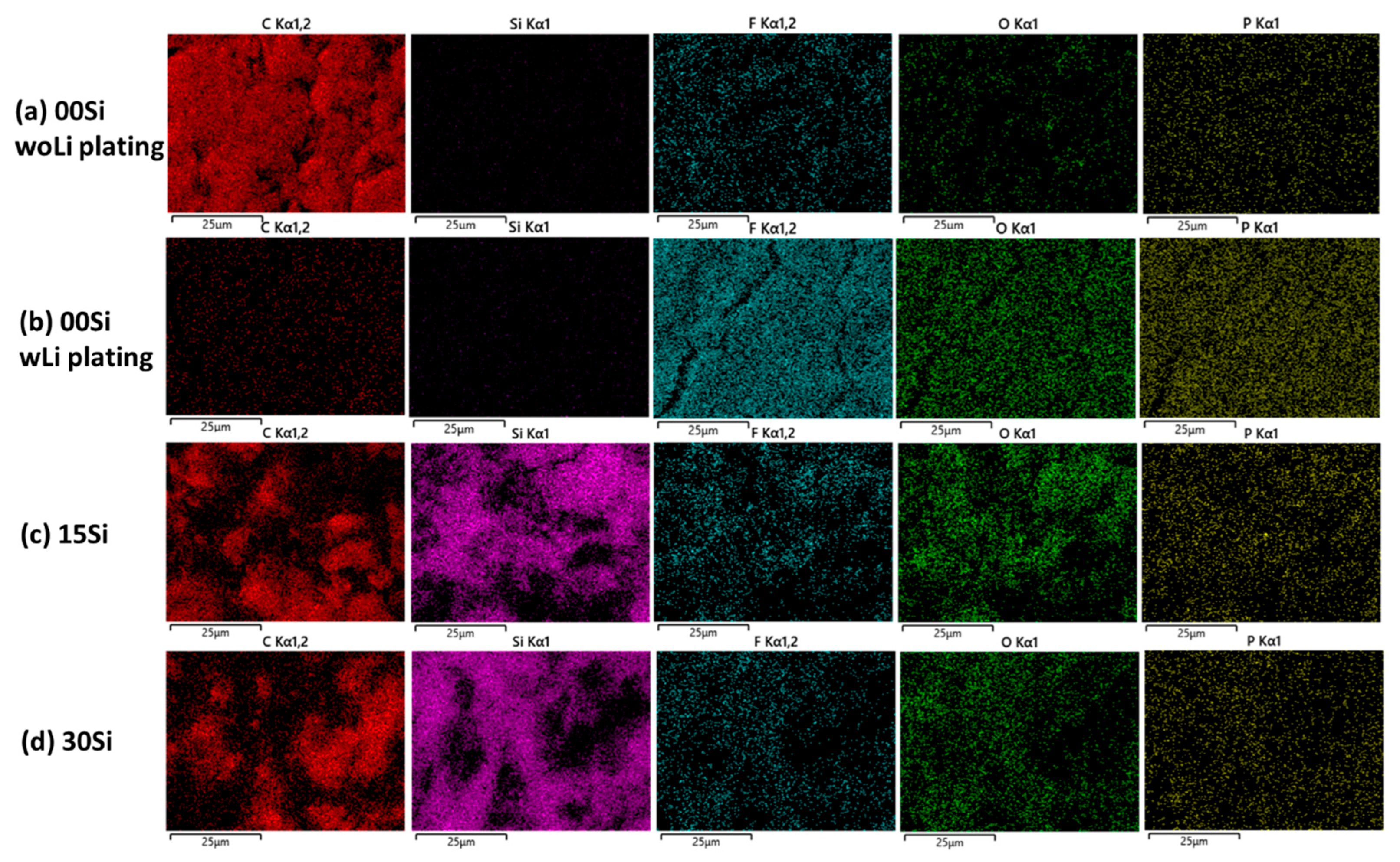
3.3. Morphology and Composition of Aged Anodes

The SEM images of the Si-Gr anodes in Figure 4 reveal the morphological changes that result from XFC cycling. The optical picture in the inset of Figure 4a shows areas with an uneven metallic coloration across the surface of the 00Si anode. Not surprisingly, the SEM images show distinct surface differences for the 00Si sample. In the black area of electrode’s edge, graphite particles are still observable, but a thin passivation film is present (Figure 4a). On the area with metallic coloration, there is complete coverage of the graphite particles by a combination of dense, thick, rod-like Li dendrite structures and the products formed by reactions of the plated lithium with the electrolyte (Figure 4b). The SEM results revealed the local heterogenous Li plating behavior on 00Si anode, which is consistent with our previous work [2,3]. Figure 4c shows a section of a 15Si composite depicting the presence of a micro-cluster of Si/SiOx nanoparticles entrapped in the graphite matrix. As seen in the SEM images (Figure 4d), the composite anode prepared with 30Si demonstrates a more uniform Si distribution than the anode containing 15% of it does. As expected, cracks are observed in the 30Si anode due to the volume change in Si during cycling. It is also important to note that these images show the minimum Li deposits on the Si containing electrodes, while 00Si showed significantly more Li plating on the surface. This is most likely due to the electrode thickness variations, besides the reduced overpotential with Si discussed above. The 00Si electrode thickness (~48 µm) is almost twice that of the other two anodes (22~27 µm). It was reported that thicker electrodes increase the possibility of there being lithium plating on the graphite surface during fast charging, owing to the ion depletion and limited mass transport in electrolytes in thick anodes [3,28]. Thus, in this regard, the thinner Si-Gr composite electrode would take advantage of the added capacity that silicon provides, while avoiding some of the issues with Li plating.
The cross-sectional SEM image in 4e shows that the average thickness of the 00Si anode is 54 μm after cycling, corresponding to a ~12% irreversible increase in thickness. The observation is consistent with previous electrochemical dilatometry experiments for pure graphite electrode thickness changes during fast charging [29]. In contrast, Figure 4f shows that the 15Si anode is 40 μm thick after 100 XFC cycles, corresponding to a 48% end-of-life swelling rate (compared to the 27 µm thick as-prepared electrode). The thickness of the 30Si electrode expands from 22 μm to 30 μm, resulting in a 36% swelling rate (Figure 4g). In addition, the cycled 30 Si anode coating shows some cracks, which extend from the surface to the copper current collector. In contrast, the 15Si anode shows no obvious particle boundaries and cracks throughout the depth, indicating that the graphite could buffer the volume changes in Si and maintain the structural integrity of the electrode during cycling to some extent.
The spatial distribution of electrolyte decomposition species including carbon, silicon, fluorine, oxygen, and phosphorus was determined with EDS elemental mapping using the SEM images in Figure 4, and the results are shown in Figure 5. The spot without Li plating on the 00Si electrode (Figure 5a) contains a uniform distribution of carbon, with some fluorine and phosphorus (arising from the electrolyte decomposition) dispersed throughout the ensemble. Oxygen was more obvious on the edge of the graphite particles. On the spot with Li plating (Figure 5b), the carbon signal was greatly reduced, while the signatures including those from fluorine, oxygen, and phosphorus in the spectra were increased significantly and distributed uniformly. The difference in the EDS maps reveals heterogeneity in the chemical composition even on the same electrode when Li plating occurred. More importantly, the top layer with Li metal promoted electrolyte decomposition due to its reactivity. There being much less carbon and more fluorine content suggest that more inorganic compounds such as LiF, LixO, and lithium (oxy)fluoro-phosphate (LixPOyFz) exist in this layer, which is consistent with the results reported by Yang et al. [3] From the map in Figure 5c,d, it can be seen fluorine distribution accumulated on the Si aggregates rather than on the Gr particles, indicating that the Si particles favor the SEI growth with salt decomposition, which is consistent with the previous report [30]. The inhomogeneity of the electrolyte decomposition products distribution in an Si-Gr composite anode affect the properties and functions of SEI layer. We suggest this plays a major role in cell degradation.

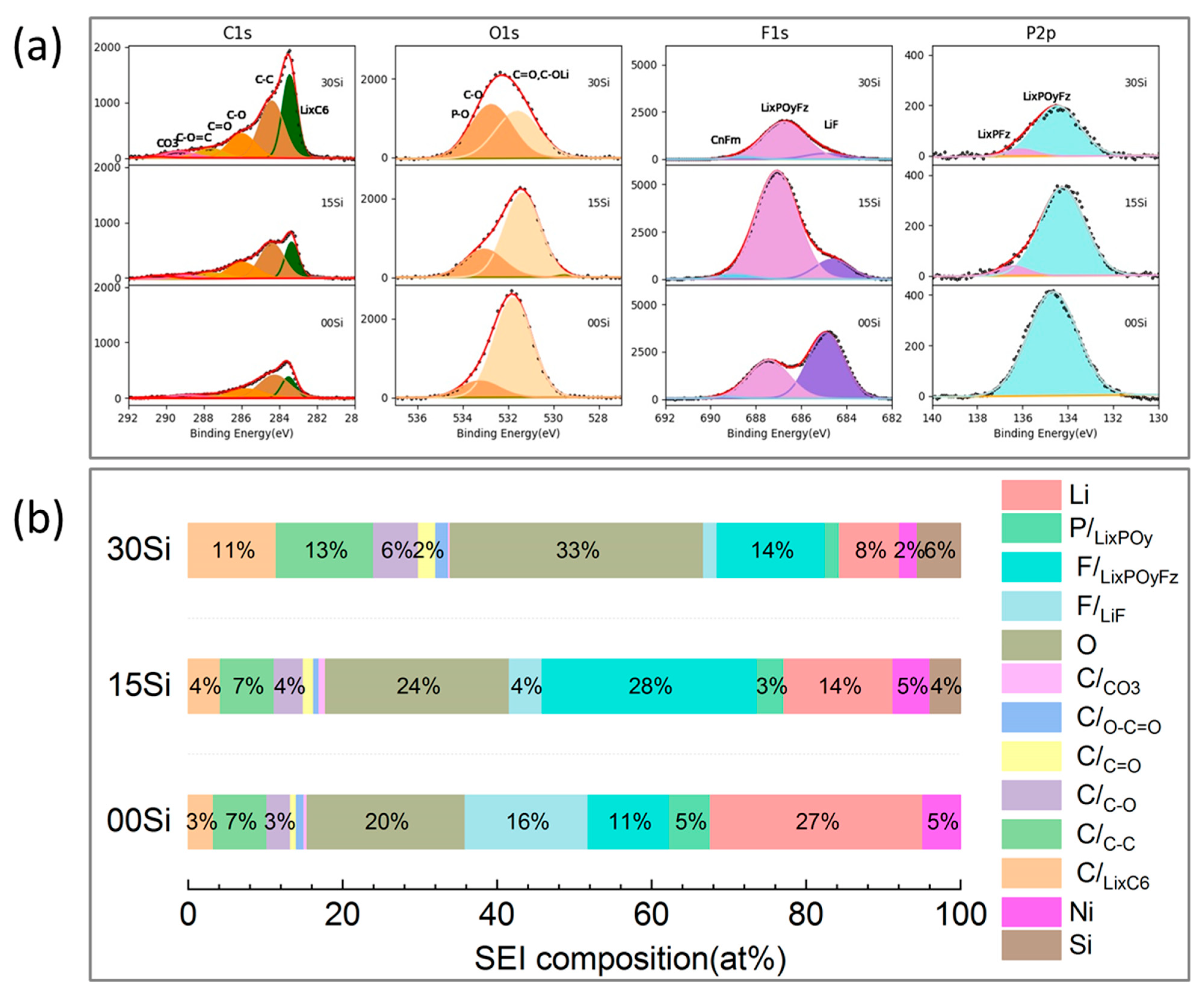
3.4. SEI Composition of the Aged Anodes

For the aforementioned anodes harvested from dissembled cells, the XPS analysis determined the impact of the Si effect on the SEI evolution and composition. Deconvolutions of the XPS spectra distinguish the contributions by various compounds. The anodes’ measured (dotted line) and curve-fitted (solid line) XPS spectra for C 1s, O 1s, F 1s, and P 2p are shown in Figure 6a after 100 XFC cycles. The integrated peak intensities are correlated with the atomic concentrations so that the relative proportions of the individual components/bonding states in the surface layer can be calculated using the atomic sensitivity factors. Figure 6b shows the relative atomic concentrations for each component for three electrodes.
A lithiated graphite peak (LixC6) is observable at the lowest photon energy value (~283 eV). In the C1s spectra in Figure 6a, therefore, the SEI layer is confirmed to be thin enough to emit photoelectrons from the underlying graphite particles. From 00Si to 30Si, the surface concentration of the lithiated graphite increases from 3 at% to 11 at%, respectively. The SEI is much thinner for the 30 Si anode compared to those of other two anodes, considering the LixC6 signal. The fraction of bulk characteristic C–C peak and hydrocarbons feature (-CH2-) at 284.4 eV for the SEI is higher in 30Si, but they are almost the same for 00 Si and 15Si. Several other carbonaceous species in the C 1s spectra at binding energies of above 285 eV are related to the breakdown of the EC solvent and are present in every anode SEI layer [2,22]. The peak at 286.2 eV increases from 00Si to 30Si cells, which is attributed to alcohols (C-OH), esters (C-O-C=O), and organic/semi-organic carbonates (C-O-C(=O)O). The peak at 290.2 eV ascribed to a carbon atom bonded with three oxygen atoms (OC(=O)O), e.g., Li2CO3 and organic carbonates, is less than 2 at%, and these peaks are comparable between each anode. The total carbon content in the SEI is sensitive and proportional to the Si content in the Si-Gr composite.
Accordingly, significant differences in the O 1s spectra peak shape are observed between the anodes. The mixture of C-O- and C=O-containing species typical of lithium acetate, lithium alkyl carbonates, and Li2CO3 was confirmed by a broad peak that dominates the O1s spectrum and is centered at about 531 eV. This major peak moves to higher binding energies from 15Si to 00Si. The peak at 533 eV is assigned to C–OH and F–P–O compounds. When Si increases to 30 wt%, the dominant environment changes, in which the contribution of C–O and F–P–O species is higher than those in the C=O environment.
The decomposition of the LiPF6 salt is indicated by the presence of PxOyFz- and LiF signals in the F 1s and P 2p spectra. The F1s spectra show that the relative intensities of the LiF and LixPOyFz are also affected by the Si content in the anode. Without Si in the anode, both LiF and LixPOyFz are major components with a slightly higher LiF ratio (16:11). However, LixPOyFz becomes the dominant compound, and the ratio of LiF: LixPOyFz decreases from 1:7 to 1:14 as the Si content increases from 15 to 30. With respect to the P2p spectra, some tiny differences were observed when we were comparing the anodes. Although LixPOyFz is the major phosphorus-containing component, a higher binding energy feature at ≈137 eV was detected in 15Si and 30 Si anodes, which is close to the value for the LiPF6 residue. It implies that due to the extensive solvent breakdown in the electrolyte, some LiPF6 salt was not completely removed by rinsing it with dimethyl carbonate (DMC), with some of it lingering in the SEI or trapped in pores on the Si-containing cells after prolonged cycling.
The overview spectra provided in Figure 6 confirm a considerable change in the elemental distribution of SEI for the cycled Si–Gr electrodes. Based on the analytical results, we can state that the Si content impacts the SEI composition of the Si-Gr composite. The baseline 00Si anode generated fewer organic species, indicating less electrolyte decomposition. Additionally, the total lithium atomic concentration is much higher for 00Si compared to those of other two anodes. However, by adding Si to the anode, SEI had higher organic contents (high C and O) due to severe electrolyte decomposition and LiPF6 hydrolysis. We believe that the resultant organic-rich SEI with Si governs the main components of the interphase layer. Consequently, the interfacial stability, ion-transport capabilities, and mechanical properties of the electrode would be affected by this organic-rich SEI, contributing to a large capacity fade [31]. As discussed in the introduction, another significant obstacle for Si-based LIB cells is their fragile and unstable surface because Si is sensitive to impurities in electrolytes such as water, carbon dioxide, and HF. The F content was the highest at the SEI in 15Si, implying more salt decomposition at this surface. Again, this trend implies that Si and Gr can potentially interact chemically during SEI formation, beside electrochemically [32]. Besides the major SEI species with C, O, F, and P, the strong Ni 2p signal found on all of the anode surfaces suggest Ni dissolution and deposition from the NMC 811 cathode. Its concentrations are similar in 00Si and 15Si, but they are smaller in 30Si. However, no clear Mn and Co signals were observed on the surface by XPS, which is consistent with our previous work when NMC811 was used as cathode. In future work, it is important to consider Ni’s function as a prominent contaminant in the SEI.

4. Conclusions

We systematically studied the effects of the Si content by employing Si-Gr composite negative electrodes and NMC811 positive electrodes in full cells using accelerated XFC aging protocols. Increasing the Si amount in the composite anode improved the rate capabilities, specific capacity, and cyclability of the cells in early XFC aging cycles. The loss of active Li due to continuous SEI reactions within the Si-Gr negative electrode likely caused an increase in the capacity fade in long term. The post-mortem analysis of electrode morphology showed electrode thickening and agglomerates of nonuniformly distributed SEI components throughout the electrode with Si added to the anode. The addition of Si was shown to reduce the possibilities of Li plating when a thin electrode was used to maintain a similar capacity compared to that of the Gr-only electrode. A mechanism showing the increase in organic components in the SEI layer because of electrolyte decomposition was also presented with the addition of Si for capacity decay. We further emphasize the importance of efforts to mitigate the degradation and aging of Si-based anodes in order to capture the potential benefits to XFC capabilities, as identified here. This work advances future work on fine-tuning the compositions and optimization of Si-Gr composites as negative electrodes, in terms of high energy density and the high stability of Li-ion batteries.

Author Contributions

Conceptualization, Z.Y.; Data curation, Z.Y.; Formal analysis, Z.Y.; Investigation, Z.Y.; Methodology, Z.Y., S.E.T. and X.W.; Project administration, B.J.I.; Resources, S.E.T. and X.W.; Visualization, B.J.I.; Writing—review and editing, Z.Y.; Writing—review and editing, Z.Y. and B.J.I. All authors have read and agreed to the published version of the manuscript.

Funding

The authors gratefully acknowledge support from the U.S. Department of Energy (DOE), Vehicle Technologies Office, specifically from Brian Cunningham and David Howell. Argonne National Laboratory is operated for DOE Office of Science by UChicago Argonne, LLC, under Contract Number DE-AC02-06CH11357. The electrodes used in this article were made by Argonne’s Cell Analysis, Modeling, and Prototyping (CAMP) Facility, which was supported by the Applied Battery Research for Transportation Program.

Data Availability Statement

The data presented in this study are available on request from the corresponding author. The data are not publicly available due to confidentiality.

Conflicts of Interest

The authors declare no conflict of interest.

References

  1. Paul, P.P.; Thampy, V.; Cao, C.; Steinrück, H.-G.; Tanim, T.R.; Dunlop, A.R.; Dufek, E.J.; Trask, S.E.; Jansen, A.N.; Toney, M.F.; et al. Quantification of heterogeneous, irreversible lithium plating in extreme fast charging of lithium-ion batteries. Energy Environ. Sci. 2021, 14, 4979–4988. [Google Scholar] [CrossRef]
  2. Yang, Z.; Kim, M.; Tsai, Y.; Zapol, P.; Trask, S.E.; Bloom, I. Extreme Fast Charging: Effect of Positive Electrode Material on Crosstalk. J. Electrochem. Soc. 2022, 169, 110505. [Google Scholar] [CrossRef]
  3. Yang, Z.; Charalambous, H.; Trask, S.E.; Montoya, A.; Jansen, A.; Wiaderek, K.M.; Bloom, I. Extreme fast charge aging: Effect of electrode loading and NMC composition on inhomogeneous degradation in graphite bulk and electrode/electrolyte interface. J. Power Sources 2022, 549, 232119. [Google Scholar] [CrossRef]
  4. Mao, C.; Ruther, R.E.; Li, J.; Du, Z.; Belharouak, I. Identifying the limiting electrode in lithium ion batteries for extreme fast charging. Electrochem. Commun. 2018, 97, 37–41. [Google Scholar] [CrossRef]
  5. Yang, Z.; Trask, S.E.; Gilbert, J.A.; Li, X.; Tsai, Y.; Jansen, A.N.; Ingram, B.J.; Bloom, I. Exploring the Promise of Multifunctional “Zintl-Phase-Forming” Electrolytes for Si-Based Full Cells. ACS Appl. Mater. Interfaces 2022, 14, 53860–53871. [Google Scholar] [CrossRef]
  6. Kim, N.; Chae, S.; Ma, J.; Ko, M.; Cho, J. Fast-charging high-energy lithium-ion batteries via implantation of amorphous silicon nanolayer in edge-plane activated graphite anodes. Nat. Commun. 2017, 8, 812. [Google Scholar] [CrossRef] [Green Version]
  7. Obrovac, M.N.; Chevrier, V.L. Alloy Negative Electrodes for Li-Ion Batteries. Chem. Rev. 2014, 114, 11444–11502. [Google Scholar] [CrossRef]
  8. Chae, S.; Ko, M.; Kim, K.; Ahn, K.; Cho, J. Confronting Issues of the Practical Implementation of Si Anode in High-Energy Lithium-Ion Batteries. Joule 2017, 1, 47–60. [Google Scholar] [CrossRef] [Green Version]
  9. Wu, H.; Chan, G.; Choi, J.W.; Ryu, I.; Yao, Y.; McDowell, M.T.; Lee, S.W.; Jackson, A.; Yang, Y.; Hu, L.; et al. Stable cycling of double-walled silicon nanotube battery anodes through solid–electrolyte interphase control. Nature Nanotechnol. 2012, 7, 310–315. [Google Scholar] [CrossRef]
  10. Zhang, L.; Liu, Y.; Key, B.; Trask, S.E.; Yang, Z.; Lu, W. Silicon Nanoparticles: Stability in Aqueous Slurries and the Optimization of the Oxide Layer Thickness for Optimal Electrochemical Performance. ACS Appl. Mater. Interfaces 2017, 9, 32727–32736. [Google Scholar] [CrossRef]
  11. Chan, C.K.; Peng, H.; Liu, G.; McIlwrath, K.; Zhang, X.F.; Huggins, R.A.; Cui, Y. High-performance lithium battery anodes using silicon nanowires. Nat. Nanotechnol. 2008, 3, 31–35. [Google Scholar] [CrossRef]
  12. Andersen, H.F.; Foss, C.E.L.; Voje, J.; Tronstad, R.; Mokkelbost, T.; Vullum, P.E.; Ulvestad, A.; Kirkengen, M.; Mæhlen, J.P. Silicon-Carbon composite anodes from industrial battery grade silicon. Sci. Rep. 2019, 9, 14814. [Google Scholar] [CrossRef] [Green Version]
  13. Bai, Y.; Cao, X.; Tian, Z.; Yang, S.; Cao, G. A high-performance silicon/carbon composite as anode material for lithium ion batteries. Nano Express 2021, 2, 010021. [Google Scholar] [CrossRef]
  14. Landa-Medrano, I.; Eguia-Barrio, A.; Sananes-Israel, S.; Porcher, W.; Trad, K.; Moretti, A.; Carvalho, D.V.; Passerini, S.; de Meatza, I. Insights into the Electrochemical Performance of 1.8 Ah Pouch and 18650 Cylindrical NMC:LFP|Si:C Blend Li-ion Cells. Batteries 2022, 8, 97. [Google Scholar] [CrossRef]
  15. Ruther, R.E.; Hays, K.A.; An, S.J.; Li, J.; Wood, D.L.; Nanda, J. Chemical Evolution in Silicon–Graphite Composite Anodes Investigated by Vibrational Spectroscopy. ACS Appl. Mater. Interfaces 2018, 10, 18641–18649. [Google Scholar] [CrossRef]
  16. Kirkaldy, N.; Samieian, M.A.; Offer, G.J.; Marinescu, M.; Patel, Y. Lithium-Ion Battery Degradation: Measuring Rapid Loss of Active Silicon in Silicon–Graphite Composite Electrodes. ACS Appl. Energy Mater. 2022, 5, 13367–13376. [Google Scholar] [CrossRef]
  17. Lee, B.S.; Oh, S.-H.; Choi, Y.J.; Yi, M.-J.; Kim, S.H.; Kim, S.-Y.; Sung, Y.-E.; Shin, S.Y.; Lee, Y.; Yu, S.-H. SiO-induced thermal instability and interplay between graphite and SiO in graphite/SiO composite anode. Nat. Commun. 2023, 14, 150. [Google Scholar] [CrossRef]
  18. Zheng, Y.; Yin, D.; Seifert, H.J.; Pfleging, W. Investigation of Fast-Charging and Degradation Processes in 3D Silicon-Graphite Anodes. Nanomaterials 2021, 12, 140. [Google Scholar] [CrossRef]
  19. Wang, S.; Ren, P.; Takyi-Aninakwa, P.; Jin, S.; Fernandez, C. A Critical Review of Improved Deep Convolutional Neural Network for Multi-Timescale State Prediction of Lithium-Ion Batteries. Energies 2022, 15, 5053. [Google Scholar] [CrossRef]
  20. Wang, S.; Takyi-Aninakwa, P.; Jin, S.; Yu, C.; Fernandez, C.; Stroe, D.-I. An improved feedforward-long short-term memory modeling method for the whole-life-cycle state of charge prediction of lithium-ion batteries considering current-voltage-temperature variation. Energy 2022, 254, 124224. [Google Scholar] [CrossRef]
  21. Browning, K.L.; Browning, J.F.; Doucet, M.; Yamada, N.L.; Liu, G.; Veith, G.M. Role of conductive binder to direct solid–electrolyte interphase formation over silicon anodes. Phys. Chem. Chem. Phys. 2019, 21, 17356–17365. [Google Scholar] [CrossRef] [PubMed]
  22. Yang, Z.; Morrissette, J.W.; Meisner, Q.; Son, S.-B.; Trask, S.E.; Tsai, Y.; Lopykinski, S.; Naik, S.; Bloom, I. Extreme Fast-Charging of Lithium-Ion Cells: Effect on Anode and Electrolyte. Energy Technol. 2021, 9, 2000696. [Google Scholar] [CrossRef]
  23. Hamzelui, N.; Eshetu, G.G.; Figgemeier, E. Customizing Active Materials and Polymeric Binders: Stern Requirements to Realize Silicon-Graphite Anode Based Lithium-Ion Batteries. J. Energy Storage 2021, 35, 102098. [Google Scholar] [CrossRef]
  24. Heubner, C.; Liebmann, T.; Lohrberg, O.; Cangaz, S.; Maletti, S.; Michaelis, A. Understanding Component-Specific Contributions and Internal Dynamics in Silicon/Graphite Blended Electrodes for High-Energy Lithium-Ion Batteries. Batter. Supercaps 2022, 5, e202100182. [Google Scholar] [CrossRef]
  25. Yao, K.P.C.; Okasinski, J.S.; Kalaga, K.; Almer, J.D.; Abraham, D.P. Operando Quantification of (De)Lithiation Behavior of Silicon–Graphite Blended Electrodes for Lithium-Ion Batteries. Adv. Energy Mater. 2019, 9, 1803380. [Google Scholar] [CrossRef]
  26. Tanim, T.R.; Paul, P.P.; Thampy, V.; Cao, C.; Steinrück, H.-G.; Nelson Weker, J.; Toney, M.F.; Dufek, E.J.; Evans, M.C.; Jansen, A.N.; et al. Heterogeneous Behavior of Lithium Plating during Extreme Fast Charging. Cell Rep. Phys. Sci. 2020, 1, 100114. [Google Scholar] [CrossRef]
  27. Moon, J.; Lee, H.C.; Jung, H.; Wakita, S.; Cho, S.; Yoon, J.; Lee, J.; Ueda, A.; Choi, B.; Lee, S.; et al. Interplay between electrochemical reactions and mechanical responses in silicon–graphite anodes and its impact on degradation. Nat. Commun. 2021, 12, 2714. [Google Scholar] [CrossRef]
  28. Usseglio-Viretta, F.L.E.; Mai, W.; Colclasure, A.M.; Doeff, M.; Yi, E.; Smith, K. Enabling fast charging of lithium-ion batteries through secondary- /dual- pore network: Part I—Analytical diffusion model. Electrochim. Acta 2020, 342, 136034. [Google Scholar] [CrossRef]
  29. Sauerteig, D.; Ivanov, S.; Reinshagen, H.; Bund, A. Reversible and irreversible dilation of lithium-ion battery electrodes investigated by in-situ dilatometry. J. Power Sources 2017, 342, 939–946. [Google Scholar] [CrossRef]
  30. Li, X.; Colclasure, A.M.; Finegan, D.P.; Ren, D.; Shi, Y.; Feng, X.; Cao, L.; Yang, Y.; Smith, K. Degradation mechanisms of high capacity 18650 cells containing Si-graphite anode and nickel-rich NMC cathode. Electrochim. Acta 2019, 297, 1109–1120. [Google Scholar] [CrossRef]
  31. Frankenberger, M.; Trunk, M.; Seidlmayer, S.; Dinter, A.; Dittloff, J.; Werner, L.; Gernhäuser, R.; Revay, Z.; Märkisch, B.; Gilles, R.; et al. SEI Growth Impacts of Lamination, Formation and Cycling in Lithium Ion Batteries. Batteries 2020, 6, 21. [Google Scholar] [CrossRef] [Green Version]
  32. Yang, Z.; Kim, M.; Yu, L.; Trask, S.E.; Bloom, I. Chemical Interplay of Silicon and Graphite in a Composite Electrode in SEI Formation. ACS Appl. Mater. Interfaces 2021, 13, 56073–56084. [Google Scholar] [CrossRef]
Figure 1. Rate capability tests at several (C-rates) for (a) 00Si, (b)15Si, and (c) 30Si electrodes in the potential range of 3.0–4.1 V versus those of NMC811. The measured specific capacities are shown in in charge (black square symbols) and discharge (red circle symbols).
Batteries 09 00138 g001
Figure 2. Cell voltage as a function of charge capacity upon charge process during rate capability test for (a) 00Si, (b) 15Si, and (c) 30Si electrodes in the potential range of 3.0–4.1 V versus those of NMC811.
Batteries 09 00138 g002
Figure 3. Average electrochemical performance of 00Si, 15Si, and 30 Si paired with NMC 811 cathode charged at 6-C (CC-CV) and discharged at 0.5-C (CC) for 100 cycles. Each composition has three duplicate cells. The plots show (a) relative discharge capacity loss at 6C, (b) coulombic efficiencies, (c) and relative discharge capacity loss at C/20 over every RPT cycles.
Batteries 09 00138 g003
Figure 4. SEM images of morphology of anodes at selected spots: (a) 00Si without Li plating, (b) 00Si with Li plating, (c) 15Si, (d) 30Si, (e) cross-sectional images of 00Si, (f) cross-sectional images of 15Si, and (g) cross-sectional images of 30Si. Inset pictures are the optical images taken from the aged anodes.
Batteries 09 00138 g004
Figure 5. Corresponding EDS mapping for the SEM images in Figure 4. (a) 00Si without Li plating, (b) 00Si with Li plating, (c) 15Si, (d) and 30Si. The column from left to right is the elemental mapping result for C, Si, F, O, and P. The scale bar is 25µm.
Batteries 09 00138 g005
Figure 6. (a) XPS spectra of C 1s, O 1s, F 1s, and P 2p core peaks of cycled Si-Gr graphite anodes paired NMC 811 cathodes after 100 XFC cycles. (b) The atomic percentage (at%) of the major SEI components determined by the curve fitting in the spectroscopy. The bar plot does not display the atomic part that is smaller than 2%.
Batteries 09 00138 g006
Table 1. Composition of electrodes used in this work. Copper foil thickness was 10 μm. Aluminum foil thickness was 20 μm.
CathodeSi-Gr Composite Anode
CompositionNMC81100Si15Si30Si
active material90 wt% NMC811 (Targray)0 wt% Paraclete Energy Si,
88 wt% Hitachi MagE3 graphite
15 wt% Paraclete Energy Si,
73 wt% Hitachi MagE3 graphite
30 wt% Paraclete Energy Si,
58 wt% Hitachi MagE3 graphite
binder5 wt% poly(vinylidene fluoride) (PVDF, Solvay 5130)10 wt% lithium polyacrylate (LiPAA)10 wt% lithium polyacrylate (LiPAA)10 wt% lithium polyacrylate (LiPAA)
conducting agent5 wt% Timcal C45 carbon2 wt% Timcal C45 carbon2 wt% Timcal C45 carbon2 wt% Timcal C45 carbon
loading density (mg/cm2)9.086.43.02.32
coating thickness (μm)33482722
N/P ratio ~1.33~1.31~1.36
Disclaimer/Publisher’s Note: The statements, opinions and data contained in all publications are solely those of the individual author(s) and contributor(s) and not of MDPI and/or the editor(s). MDPI and/or the editor(s) disclaim responsibility for any injury to people or property resulting from any ideas, methods, instructions or products referred to in the content.

