

High Performance H2−Mn Regenerative Fuel Cells through an Improved Positive Electrode Morphology


 ,
,  ,
,  and
and 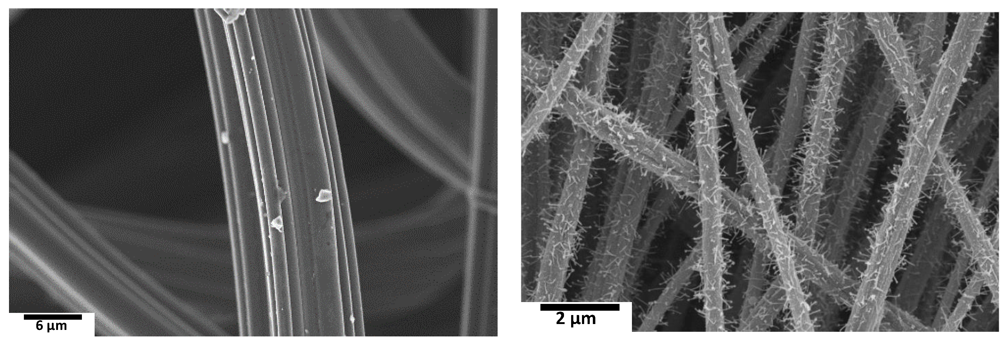
Abstract
:1. Introduction
2. Experimental
2.1. Chemicals
2.2. Membrane Electrode Assembly (MEA)
2.3. Electrospinning and Carbonization
2.4. Redox Flow Battery Cell Assembly
2.5. Charge−Discharge Experiments
3. Results and Discussion
3.1. Morphological Characterization of Electrodes
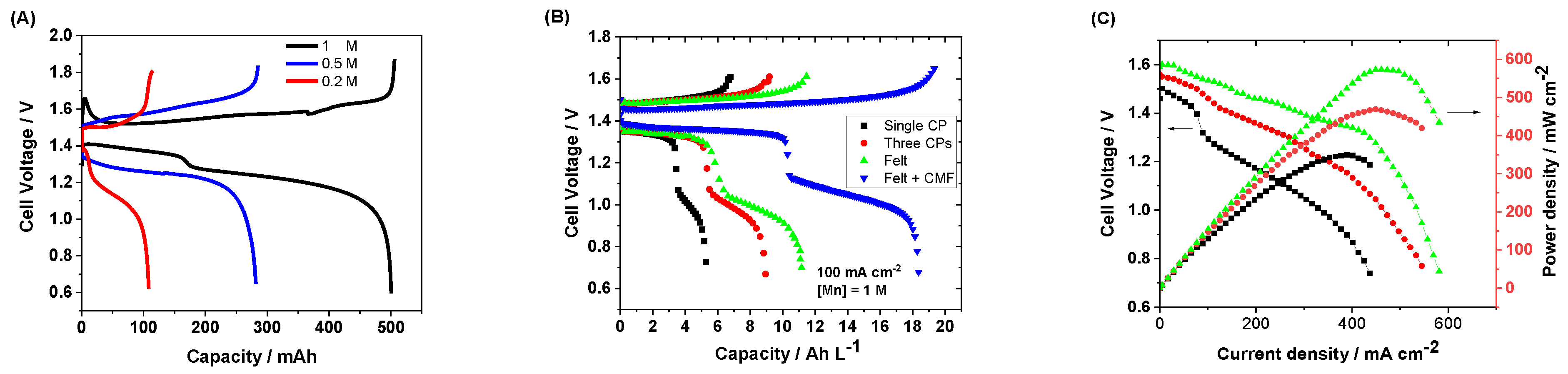
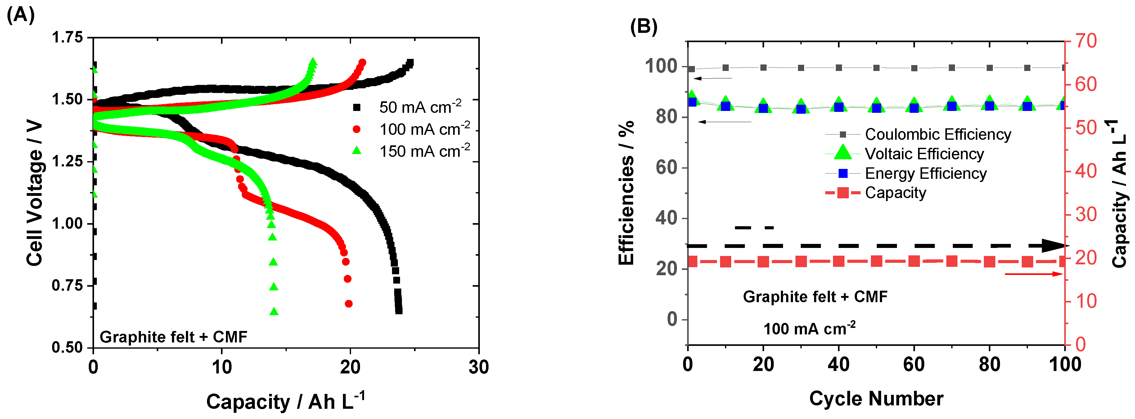
3.2. Single Carbon Paper Electrodes
4. Future Perspectives
Author Contributions
Funding
Data Availability Statement
Acknowledgments
Conflicts of Interest
References
- Chakrabarti, M.H.; Hajimolana, S.A.; Mjalli, F.S.; Saleem, M.; Mustafa, I. Redox Flow Battery for Energy Storage. Arab. J. Sci. Eng. 2013, 38, 723–739. [Google Scholar] [CrossRef]
- Arenas, L.F.; Ponce de León, C.; Walsh, F.C. Redox flow batteries for energy storage: Their promise, achievements and challenges. Curr. Opin. Electrochem. 2019, 16, 117–126. [Google Scholar] [CrossRef]
- Chakrabarti, B.K.; Kalamaras, E.; Singh, A.K.; Bertei, A.; Rubio-Garcia, J.; Yufit, V.; Tenny, K.M.; Wu, B.; Tariq, F.; Hajimolana, Y.S.; et al. Modelling of redox flow battery electrode processes at a range of length scales: A review. Sustain. Energy Fuels 2020, 4, 5433–5468. [Google Scholar] [CrossRef]
- Gencten, M.; Sahin, Y. A critical review on progress of the electrode materials of vanadium redox flow battery. Int. J. Energy Res. 2020, 44, 7903–7923. [Google Scholar] [CrossRef]
- Chakrabarti, B.; Yufit, V.; Kavei, A.; Xia, Y.; Stevenson, G.; Kalamaras, E.; Luo, H.; Feng, J.; Tariq, F.; Taiwo, O.; et al. Charge/discharge and cycling performance of flexible carbon paper electrodes in a regenerative hydrogen/vanadium fuel cell. Int. J. Hydrog. Energy 2019, 44, 30093–30107. [Google Scholar] [CrossRef]
- Jervis, R.; Kok, M.D.R.; Neville, T.P.; Meyer, Q.; Brown, L.D.; Iacoviello, F.; Gostick, J.T.; Brett, D.J.L.; Shearing, P.R. In situ compression and X-ray computed tomography of flow battery electrodes. J. Energy Chem. 2018, 27, 1353–1361. [Google Scholar] [CrossRef]
- Chakrabarti, B.; Rubio-Garcia, J.; Kalamaras, E.; Yufit, V.; Tariq, F.; Low, C.T.J.; Kucernak, A.; Brandon, N. Evaluation of a Non-Aqueous Vanadium Redox Flow Battery Using a Deep Eutectic Solvent and Graphene-Modified Carbon Electrodes via Electrophoretic Deposition. Batteries 2020, 6, 38. [Google Scholar] [CrossRef]
- Flox, C.; Fàbrega, C.; Andreu, T.; Morata, A.; Skoumal, M.; Rubio-Garcia, J.; Morante, J.R. Highly electrocatalytic flexible nanofiber for improved vanadium-based redox flow battery cathode electrodes. RSC Adv. 2013, 3, 12056–12059. [Google Scholar] [CrossRef]
- Tariq, F.; Rubio-Garcia, J.; Yufit, V.; Bertei, A.; Chakrabarti, B.K.; Kucernak, A.; Brandon, N. Uncovering the mechanisms of electrolyte permeation in porous electrodes for redox flow batteries through real time in situ 3D imaging. Sustain. Energy Fuels 2018, 2, 2068–2080. [Google Scholar] [CrossRef]
- Ghasemiestahbanati, E.; Shaibani, M.; Konstas, K.; Chakrabarti, B.K.; Low, C.T.J.; Majumder, M.; Hill, M.R. Charge Carrier Molecular Sieve (CCMS) Membranes with Anti-aging Effect for Long-Life Vanadium Redox Flow Batteries. ACS Appl. Energy Mater. 2022, 5, 1505–1515. [Google Scholar] [CrossRef]
- Hassan, A.; Tzedakis, T. Facile chemical activation of graphite felt by KMnO4 acidic solution for vanadium redox flow batteries. Appl. Surf. Sci. 2020, 528, 146808. [Google Scholar] [CrossRef]
- Chakrabarti, B.; Nir, D.; Yufit, V.; Tariq, F.; Rubio-Garcia, J.; Maher, R.; Kucernak, A.; Aravind, P.V.; Brandon, N. Performance Enhancement of Reduced Graphene Oxide-Modified Carbon Electrodes for Vanadium Redox-Flow Systems. ChemElectroChem 2017, 4, 194–200. [Google Scholar] [CrossRef]
- Rubio-Garcia, J.; Cui, J.; Parra-Puerto, A.; Kucernak, A. Hydrogen/Vanadium Hybrid Redox Flow Battery with enhanced electrolyte concentration. Energy Storage Mater. 2020, 31, 1–10. [Google Scholar] [CrossRef]
- Chakrabarti, B.K.; Gençten, M.; Bree, G.; Dao, A.H.; Mandler, D.; Low, C.T.J. Modern practices in electrophoretic deposition to manufacture energy storage electrodes. Int. J. Energy Res. 2022, 46, 13205–13250. [Google Scholar] [CrossRef]
- Jacquemond, R.R.; Wan, C.T.-C.; Chiang, Y.-M.; Borneman, Z.; Brushett, F.R.; Nijmeijer, K.; Forner-Cuenca, A. Microstructural engineering of high-power redox flow battery electrodes via non-solvent induced phase separation. Cell Rep. Phys. Sci. 2022, 3, 100943. [Google Scholar] [CrossRef]
- Dai, W.; Wang, H.; Yuan, X.-Z.; Martin, J.J.; Yang, D.; Qiao, J.; Ma, J. A review on water balance in the membrane electrode assembly of proton exchange membrane fuel cells. Int. J. Hydrog. Energy 2009, 34, 9461–9478. [Google Scholar] [CrossRef]
- Chakrabarti, B.K.; Kalamaras, E.; Ouyang, M.; Liu, X.; Remy, G.; Wilson, P.F.; Williams, M.A.; Rubio-Garcia, J.; Yufit, V.; Bree, G.; et al. Trichome-like Carbon-Metal Fabrics Made of Carbon Microfibers, Carbon Nanotubes, and Fe-Based Nanoparticles as Electrodes for Regenerative Hydrogen/Vanadium Flow Cells. ACS Appl. Nano Mater. 2021, 4, 10754–10763. [Google Scholar] [CrossRef]
- Hwang, D.S.; Park, C.H.; Yi, S.C.; Lee, Y.M. Optimal catalyst layer structure of polymer electrolyte membrane fuel cell. Int. J. Hydrog. Energy 2011, 36, 9876–9885. [Google Scholar] [CrossRef]
- Sharma, R.; Kar, K.K. Hierarchically structured catalyst layer for the oxygen reduction reaction fabricated by electrodeposition of platinum on carbon nanotube coated carbon fiber. RSC Adv. 2015, 5, 66518–66527. [Google Scholar] [CrossRef]
- Rajabalizadeh Mojarrad, N.; Iskandarani, B.; Taşdemir, A.; Yürüm, A.; Alkan Gürsel, S.; Yarar Kaplan, B. Nanofiber based hybrid sulfonated silica/P(VDF-TrFE) membranes for PEM fuel cells. Int. J. Hydrog. Energy 2021, 46, 13583–13593. [Google Scholar] [CrossRef]
- Iskandarani, B.; Rajabalizadeh Mojarrad, N.; Yürüm, A.; Alkan Gürsel, S.; Yarar Kaplan, B. Electrospun Nanofiber Electrodes for Boosted Performance and Durability at Lower Humidity Operation of PEM Fuel Cells. Energy Fuels 2022, 36, 9282–9294. [Google Scholar] [CrossRef]
- Liu, X.; Ouyang, M.; Orzech, M.W.; Niu, Y.; Tang, W.; Chen, J.; Marlow, M.N.; Puhan, D.; Zhao, Y.; Tan, R.; et al. In-situ fabrication of carbon-metal fabrics as freestanding electrodes for high-performance flexible energy storage devices. Energy Storage Mater. 2020, 30, 329–336. [Google Scholar] [CrossRef]
- Chakrabarti, B.K.; Feng, J.; Kalamaras, E.; Rubio-Garcia, J.; George, C.; Luo, H.; Xia, Y.; Yufit, V.; Titirici, M.-M.; Low, C.T.J.; et al. Hybrid Redox Flow Cells with Enhanced Electrochemical Performance via Binderless and Electrophoretically Deposited Nitrogen-Doped Graphene on Carbon Paper Electrodes. ACS Appl. Mater. Interfaces 2020, 12, 53869–53878. [Google Scholar] [CrossRef]
- Singh, N.; McFarland, E.W. Levelized cost of energy and sensitivity analysis for the hydrogen–bromine flow battery. J. Power Sources 2015, 288, 187–198. [Google Scholar] [CrossRef]
- Cho, K.T.; Tucker, M.C.; Ding, M.; Ridgway, P.; Battaglia, V.S.; Srinivasan, V.; Weber, A.Z. Cyclic Performance Analysis of Hydrogen/Bromine Flow Batteries for Grid-Scale Energy Storage. ChemPlusChem 2015, 80, 402–411. [Google Scholar] [CrossRef]
- Lyday, P.A. Bromine; Bureau of Mines, US Department of the Interior Information: Washington, DC, USA, 1985.
- Pino-Muñoz, C.A.; Chakrabarti, B.K.; Yufit, V.; Brandon, N.P. Characterization of a Regenerative Hydrogen-Vanadium Fuel Cell Using an Experimentally Validated Unit Cell Model. J. Electrochem. Soc. 2019, 166, A3511–A3524. [Google Scholar] [CrossRef]
- Leung, P.K.; Ponce-de-León, C.; Low, C.T.J.; Shah, A.A.; Walsh, F.C. Characterization of a zinc–cerium flow battery. J. Power Sources 2011, 196, 5174–5185. [Google Scholar] [CrossRef]
- Kordesh, K.; Weissenbacher, M. Rechargeable alkaline manganese dioxide/zinc batteries. J. Power Sources 1994, 51, 61–78. [Google Scholar] [CrossRef]
- Reynard, D.; Maye, S.; Peljo, P.; Chanda, V.; Girault, H.H.; Gentil, S. Vanadium–Manganese Redox Flow Battery: Study of MnIII Disproportionation in the Presence of Other Metallic Ions. Chem. Eur. J. 2020, 26, 7250–7257. [Google Scholar] [CrossRef] [PubMed]
- Rubio-Garcia, J.; Kucernak, A.; Zhao, D.; Li, D.; Fahy, K.; Yufit, V.; Brandon, N.; Gomez-Gonzalez, M. Hydrogen/manganese hybrid redox flow battery. J. Phys. Energy 2019, 1, 015006. [Google Scholar] [CrossRef]
- Liu, H.; Li, P.; Juarez-Robles, D.; Wang, K.; Hernandez-Guerrero, A. Experimental Study and Comparison of Various Designs of Gas Flow Fields to PEM Fuel Cells and Cell Stack Performance. Front. Energy Res. 2014, 2, 2. [Google Scholar] [CrossRef]
- Zhang, L.; Yue, J.; Deng, Q.; Ling, W.; Zhou, C.-J.; Zeng, X.-X.; Zhou, C.; Wu, X.-W.; Wu, Y. Preparation of a porous graphite felt electrode for advance vanadium redox flow batteries. RSC Adv. 2020, 10, 13374–13378. [Google Scholar] [CrossRef]
- Xue, F.-Q.; Wang, Y.-L.; Wang, W.-H.; Wang, X.-D. Investigation on the electrode process of the Mn(II)/Mn(III) couple in redox flow battery. Electrochim. Acta 2008, 53, 6636–6642. [Google Scholar] [CrossRef]
- Jiang, Q.; Ren, Y.; Yang, Y.; Wang, L.; Dai, L.; He, Z. Recent advances in carbon-based electrocatalysts for vanadium redox flow battery: Mechanisms, properties, and perspectives. Compos. Part B Eng. 2022, 242, 110094. [Google Scholar] [CrossRef]
- Houser, J.; Clement, J.; Pezeshki, A.; Mench, M.M. Influence of architecture and material properties on vanadium redox flow battery performance. J. Power Sources 2016, 302, 369–377. [Google Scholar] [CrossRef]
- Forner-Cuenca, A.; Penn, E.E.; Oliveira, A.M.; Brushett, F.R. Exploring the Role of Electrode Microstructure on the Performance of Non-Aqueous Redox Flow Batteries. J. Electrochem. Soc. 2019, 166, A2230. [Google Scholar] [CrossRef]
- Karaeyvaz, M.C.; Duman, B.; Fıçıcılar, B. An alternative HCMS carbon catalyst in bromine reduction reaction for hydrogen-bromine flow batteries. Int. J. Hydrog. Energy 2021, 46, 29512–29522. [Google Scholar] [CrossRef]
- Zheng, Q.; Xing, F.; Li, X.; Liu, T.; Lai, Q.; Ning, G.; Zhang, H. Investigation on the performance evaluation method of flow batteries. J. Power Sources 2014, 266, 145–149. [Google Scholar] [CrossRef]
- Thielke, M.W.; Tian, G.; Sobrido, A.J. Sustainable electrodes for the next generation of redox flow batteries. J. Phys. Mater. 2022, 5, 024004. [Google Scholar] [CrossRef]


Disclaimer/Publisher’s Note: The statements, opinions and data contained in all publications are solely those of the individual author(s) and contributor(s) and not of MDPI and/or the editor(s). MDPI and/or the editor(s) disclaim responsibility for any injury to people or property resulting from any ideas, methods, instructions or products referred to in the content. |
© 2023 by the authors. Licensee MDPI, Basel, Switzerland. This article is an open access article distributed under the terms and conditions of the Creative Commons Attribution (CC BY) license (https://creativecommons.org/licenses/by/4.0/).
Share and Cite
Rubio-Garcia, J.; Kucernak, A.; Chakrabarti, B.K.; Zhao, D.; Li, D.; Tang, Y.; Ouyang, M.; Low, C.T.J.; Brandon, N. High Performance H2−Mn Regenerative Fuel Cells through an Improved Positive Electrode Morphology. Batteries 2023, 9, 108. https://doi.org/10.3390/batteries9020108
Rubio-Garcia J, Kucernak A, Chakrabarti BK, Zhao D, Li D, Tang Y, Ouyang M, Low CTJ, Brandon N. High Performance H2−Mn Regenerative Fuel Cells through an Improved Positive Electrode Morphology. Batteries. 2023; 9(2):108. https://doi.org/10.3390/batteries9020108
Chicago/Turabian StyleRubio-Garcia, Javier, Anthony Kucernak, Barun Kumar Chakrabarti, Dong Zhao, Danlei Li, Yuchen Tang, Mengzheng Ouyang, Chee Tong John Low, and Nigel Brandon. 2023. "High Performance H2−Mn Regenerative Fuel Cells through an Improved Positive Electrode Morphology" Batteries 9, no. 2: 108. https://doi.org/10.3390/batteries9020108
APA StyleRubio-Garcia, J., Kucernak, A., Chakrabarti, B. K., Zhao, D., Li, D., Tang, Y., Ouyang, M., Low, C. T. J., & Brandon, N. (2023). High Performance H2−Mn Regenerative Fuel Cells through an Improved Positive Electrode Morphology. Batteries, 9(2), 108. https://doi.org/10.3390/batteries9020108