Article

Interface Stability between Na3Zr2Si2PO12 Solid Electrolyte and Sodium Metal Anode for Quasi-Solid-State Sodium Battery

Center for Cooperative Research on Alternative Energies (CIC energiGUNE), Basque Research and Technology Alliance (BRTA), Parque Tecnológico de Álava, Albert Einstein, 48, 01510 Vitoria-Gasteiz, Spain
*
Authors to whom correspondence should be addressed.
Batteries 2023, 9(1), 8; https://doi.org/10.3390/batteries9010008
Submission received: 22 November 2022 / Revised: 16 December 2022 / Accepted: 20 December 2022 / Published: 23 December 2022

Abstract

:
Solid electrolytes are renowned for their nonflammable, dendrite-blocking qualities, which also exhibit stability over large potential windows. NASICON-type Na1+xZr2SixP3-xO12 (NZSP) is a well-known solid electrolyte material for sodium metal batteries owing to its elevated room temperature sodium-ion (Na+) conductivity and good electrochemical stability. Nevertheless, the strong electrode–electrolyte interfacial resistance restricts its implementation in sodium metal batteries and remains a significant challenge. In this work, we present an efficacious process to enhance the sodium wettability of Na3Zr2Si2PO12 by sputtering a thin gold (Au) interlayer. Our experimental investigation indicates a substantial reduction in interfacial resistance, from 2708 Ω cm2 to 146 Ω cm2, by employing a fine Au interlayer between the Na metal and the NZSP electrolyte. The symmetrical Na||NZSP||Na with a gold interlayer cell shows a steady Na stripping/plating at a high current density of 320 µA cm−2. A quasi-solid-state battery, with NaFePO4 (NFP) as a cathode, metallic sodium as an anode, and a Au-sputtered NZSP electrolyte with polypropylene (PP) soaked in electrolyte as an intermediate layer on the cathode, exhibited a discharge capacity of 100 mAh g−1 and a ~100% Coulombic efficiency at 50 μA cm−2 after the 50th charge/discharge cycle at room temperature (RT).

1. Introduction

In view of the increasing energy demand within modern society over the last few decades, energy storage has become the subject of growing global concern. In this field, lithium-ion batteries (LIBs) are one of the great successes for energy storage applications in recent times, dominating the market for portable electronics and hybrid and electric vehicles due to its high volumetric and gravimetric energy densities. However, lithium is not cost-effective and is considered a critical raw material with limited supply. This, together with the use of cobalt and nickel in the positive electrode, have been raised as concerns about the future and long-term availability [1].
Subsequently, sodium-ion batteries (SIBs) are one of the most appealing alternatives to LIBs due to their low cost, abundance, and the sustainability of the resources, together with the similarities in the physical and chemical properties between Li- and Na-containing compounds [2,3,4,5]. For developing advanced sodium-ion batteries with high energy densities and long cycle lives, several cathode and anode materials have been proposed [6,7,8,9,10]. However, the present SIBs with organic liquid electrolytes generally demonstrate numerous drawbacks, comprising narrow electrochemical windows, electrolyte leakage, flammability, and poor cycle lives [11,12,13]. Consequently, due to the high energy density and improved safety, solid-state sodium batteries have been proposed for the next generation of energy storage systems [14,15,16,17,18]. Solid electrolytes must play a critical role in this development since they need to possess high sodium-ionic conductivity and negligible electronic conductivity at RT, have wide electrochemical stability, be compatible with electrode materials, and have excellent mechanical properties to control the sodium dendrite formation [19,20].
Sodium-based solid-state electrolytes are generally categorized into inorganic solid electrolytes, solid polymer electrolytes, or composite solid electrolytes. Among inorganic solid electrolytes, Na-β”-Al2O3, NASICON, and glass–ceramic sulfides are the most widely investigated [21]. A NASICON-structured electrolyte, with the nominal composition Na1+xZr2SixP3-xO12 (NZSP), proposed by Hong et al. [22,23], has been extensively explored due to its high ionic conductivity (10−4 S cm−1 at RT), good electrochemical stability, and wide potential window, as well as its superior chemical and mechanical stability. The NZSP structure consists of a 3-dimensional (3D) framework of ZrO6 octahedra that shares corners with both PO4 and SiO4 tetrahedra, creating large tunnels to facilitate Na+ ions from one site to another via “bottlenecks”, created by means of the oxygen ions [24,25,26]. The NASICON framework has also drawn considerable interest and high significance due to its excellent moisture stability and good electrochemical window against sodium metal [27,28,29,30,31,32]. Nevertheless, the surface roughness of sintered NZSP solid electrolytes generates microscopic gaps at the interface, leading to poor wettability with the sodium metal anode. While cycling, an inhomogeneous Na+ flux occurs over the interface, leading to a huge interfacial impedance, severe dendritic growth, and immediate short-circuiting [19,33]. Reducing the interfacial resistance between the solid electrolyte and the electrodes remains more challenging than enhancing the bulk ionic conductivity of the solid electrolytes [34].
The interfacial issue between Na-metal/NZSP ceramic might be resolved by constructing a stable interface interlayer that establishes a good surface wettability with the anode and acts as a conductor of the working ion, and recently, various strategies have been introduced to improve this. Gao et al. published a simple post-treatment at 450 °C that aids in decomposing the byproduct, which acts as an insulator on the NZSP surface, subsequently reducing the Na/NZSP interfacial resistance [35]. Using a spin-coating procedure, Miao et al. deposited a thin layer of AlF3 to act as a buffer layer between the sodium anode and NZSP to enhance the anode–electrolyte wettability [36]. To enhance the ability of the Na+-ion transfer at the Na/NZSP interface, high temperature and pressure are also occasionally utilized [37]. Yang et al. drastically reduced the interface resistance between Na and NZSP from 581 to 3 Ω cm2 by introducing SnOx/Sn film as an interlayer, and the constructed symmetric cell maintained good cyclability over 1500 h at 0.1 mA cm−2 at room temperature [38]. Furthermore, Zhou et al. demonstrated the value of using a polymer interlayer to prevent sodium dendrite formation, thereby reducing the interfacial resistance, as well as increasing the electrolyte’s wetting with the sodium anode and providing a homogenous Na+-ion flux over the interface [19]. Alternatively, introducing a metal/metal oxide interlayer between the solid electrolyte and the anode is a prevention strategy used in solid-state lithium batteries. Indeed, a thin coating of Al, Si, Sn, Ge, ZnO, Al2O3, etc., has proved able to turn the lithiophobic surface of the garnet electrolytes lithiophilic instead [39,40,41,42,43,44,45,46,47]. The coated metal oxide serves as a lithium-ion-conducting layer and helps reduce the interfacial resistance comparative to that of the lithiophobic garnet. Tsai et al. [46] and Park et al. [48] demonstrated that a thin layer of gold (Au) is able to lower the impedance of the garnet solid electrolyte by means of alloying lithium with gold. The alloying reaction of the metallic interlayer with lithium leads to close contact with the solid electrolyte, thus improving the lithium-ion kinetics at the anode–electrolyte interface. This mitigates the interfacial resistance and barricades the lithium dendrite growth. In addition, it is important that the coated metal/metal oxide interlayer should be very thin. It also acts as an excellent ionic conductor, thereby ensuring sufficient ion conductivity in order to enhance Li-ion migration at the interface [39,40,41,42,43,44,45,46,47,48,49,50].
Inspired by the above-mentioned reports, we hereby modified the surface of the Na3Zr2Si2PO12 solid electrolyte by sputtering a thin layer of Au through direct-current (DC) sputtering, which was found to substantially enhance the surface wettability of the Na3Zr2Si2PO12 solid electrolyte. The sodium can react with the Au on the NZSP electrolyte’s surface, resulting in the formation of Na–Au alloys that significantly reduce the interfacial resistance. Thus, the formed Na–Au alloy acts as a Na-ion conductor between the NZSP electrolyte and Na metal. A quasi-solid-state battery, comprising NaFePO4 as the cathode, metallic sodium as the anode, and Au-sputtered Na3Zr2Si2PO12 as the electrolyte, was found to provide a stable cycling performance at room temperature. Finally, to enhance the cathode NZSP interface, a thin polypropylene (PP) separator soaked in liquid electrolyte was subsequently employed as an interlayer.

2. Experimental Section

2.1. Synthesis of Na3Zr2Si2PO12

NASICON structured Na3Zr2Si2PO12 was prepared using the solid-state reaction technique [32]. High-purity Na3PO4 (Sigma-Aldrich, Germany 10 wt.% used in excess to compensate for loss during subsequent heat treatment), ZrO2 (Alfa-Aeser, United States, 99%,), and SiO2 (Sigma-Aldrich, Germany,98%) were ball-milled (Pulverisette 7, Fritsch, Germany) in a ZrO2 container with an isopropanol solvent for ca. 6 h at 300 RPM. After solvent evaporation, the sample was heat-treated at 900 °C for 12 h to remove of any volatile elements. After cooling, the powders were once again ball-milled for 6 h at 500 RPM. The resulting samples were ground and then pelletized using isostatic pressure at ∼300 MPa. The pellets covered with the same mother powder to decrease sodium loss were transferred into an alumina crucible and heated for 12 h at 1230 °C with a heating rate of 5 °C/min.

2.2. Structural Characterization

The purity and the crystal structure of the samples were analyzed with powder X-ray diffraction (PXRD) utilizing a BRUKER D8 Discover X-ray diffractometer provided with a LYNXEYE XE detector using Cu radiation (λ: Kα1 = 1.54060 Å, Kα2 = 1.54440 Å). The measurements were made with a 0.020° step size and a total time/step of 184.90 s.

2.3. Microstructural Characterization

The cross section morphologies of the sintered pellets were characterized using a Thermo Fisher Quanta 200 FEG high-resolution scanning electron microscope (SEM) operated between 3 kV (low-vacuum mode) and 30 kV (high-vacuum mode) coupled with an EDS spectrophotometer from EDAX for elemental composition analysis. Prior to SEM measurements, the samples were sectioned transversally using Hitachi 4000 Plus ion milling, which employs a wide, low-energy Ar+-ion beam (0–6 kV acceleration voltage) milling process to generate broader, undistorted cross section milling with no mechanical stress to the material. The surface topography of the deposited Au layer on the NZSP pellet was characterized using atomic force microscopy (AFM). All AFM images were collected using the tapping mode of operation with Aglient 5500 AFM noncoated silicon cantilevers (APP Nano) with a minimal spring constant of 40 N/m and a resonant frequency of 264 kHz.

2.4. Fabrication of the Symmetric Cells

The NZSP pellets were mirror-polished using a series of sandpapers (400, 600, 1200, and 2500 grits) to reduce the thickness to ~500 μm and then further cleaned with isopropanol and dried in an oven at 120 °C before moving into glove box for the battery assembly. Two types of cell configuration were adopted for this study:
(i)
Na||NZSP||Na: A Swagelok-type cell was assembled by placing the sodium foil on both surfaces of the pellet by applying a gentle pressure. The cell was then heated to 80 °C overnight under an argon atmosphere to soften the sodium and thus enhance the contact.
(ii)
Na||Au-NZSP-Au||Na: A thin layer of gold was sputtered for 1 min on each side of the NZSP at a current of 50 µA using the DC-sputtering technique. The coated sample was then moved to the glove box. Subsequently, sodium discs were placed above the Au-sputtered NSZP, and a Swagelok-type cell was fabricated. The Swagelok cell was then heated to 80 °C overnight to form a sodium–gold alloy.

2.5. Electrical Conductivity Studies

Impedance measurements were performed on the sintered pellets in a temperature range between room temperature and 250 °C using a biologic VMP3 multichannel potentiostat. Prior to the measurements, the samples were painted with Au and cured at 600 °C for 1 h.

2.6. Electrode Preparation

A NaFePO4 cathode material was synthesized via chemical delithiation and the subsequent chemical sodiation of commercial LiFePO4 [51]. High-purity NFP:C65 (in the stoichiometric ratio 80:10) was weighed and blended using an agate mortar and pestle. The obtained cathode mixture was then mixed with polyvinylidene difluoride (PVDF-10 wt.%) binder using N-methyl pyrrolidinone (NMP) as a solvent. The resulting slurry was coated on aluminum foil using a doctor’s blade. The coated electrode was further dried overnight at 80 °C in a vacuum oven and then punched into 12 mm diameter circular discs. The areal loading of the NFP cathode was found to be ~3 mg cm−2 in all cases.

2.7. Fabrication of the Quasi-Solid-State Sodium Metal Battery

A quasi-solid-state battery was constructed with sodium metal anode, NFP cathode, and Au-sputtered NZSP electrolyte. Initially, the cell with the Au-sputtered NZSP electrolyte and Na anode was heat-treated at 80 °C to soften the sodium. Later, to decrease the interfacial resistance between the NZSP electrolyte and NFP cathode, a PP separator wetted with 10 μL of liquid electrolyte containing 1.0 M NaPF6 in ethylene carbonate:dimethyl carbonate:diethyl carbonate (1M NaPF6 EC:DMC:DEC, 2:1:1 v/v%) was kept between NZSP and NFP. The CR2032 coin cell, with the configuration Na-Au||NZSP||PP-NFP, was then assembled in an argon-filled glove box.

2.8. Electrochemical Characterization

The fabricated symmetric and full cells were investigated using electrochemical impedance spectroscopy (EIS) and galvanostatic charge–discharge measurements using a BioLogic battery tester. EIS experiments on the symmetric cell were performed in the frequency range between 1 MHz and 10 Hz, with a 10 mV excitation amplitude. Sodium-plating/stripping tests were performed at different current densities for 10 min at 25 °C between −5 and +5 V. The galvanostatic charge–discharge evaluation was carried out on the full cell at 50, 100, and 150 μA cm−2, in the voltage window between 1.5 and 4.0 V vs. Na+/Na at 25 °C.

3. Results and Discussions

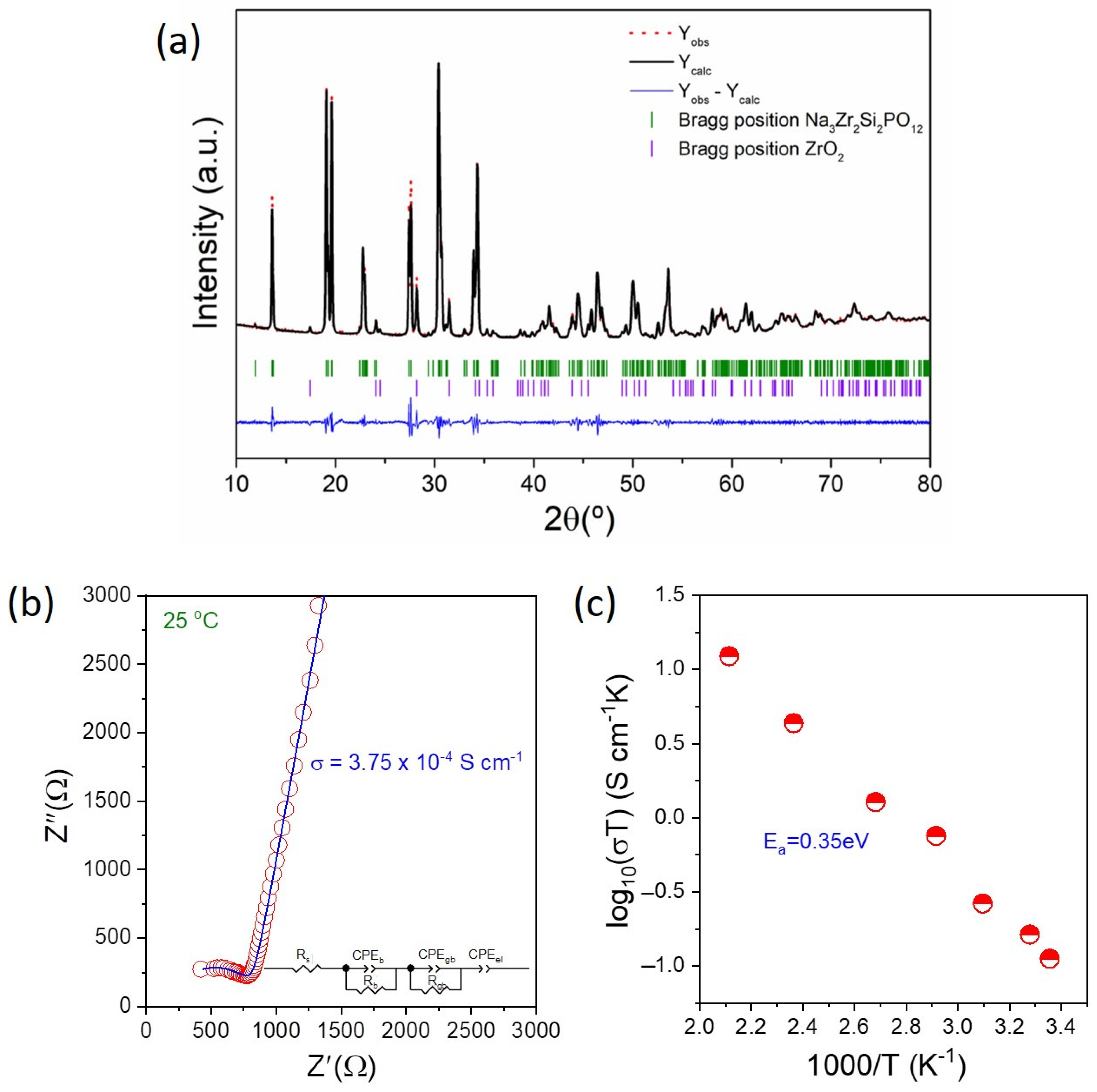
3.1. Characterization of Na3Zr2Si2PO12

The Le Bail refinement of PXRD patterns of Na3Zr2Si2PO12 heated at 1230 °C for 12 h (Figure 1a) confirms that the main phase consists of monoclinic NASICON with a C2/c space group. The refined cell parameters a = 15.6345(6) Å, b = 9.0445(3) Å, c = 9.2209(3) Å, and β = 123.707(2)° are in agreement with those previously reported [52]. As seen from Figure 1a), a small amount of secondary-phase ZrO2 was detected. [53,54,55] The impedance plot for NZSP (Figure 1b) has a semicircle and a capacitive tail in the high- and low-frequency regions, which correspond to bulk contribution and Na-ion-blocking Au electrodes, respectively. In this study, two parallel combinations of resistances (R) and constant phase elements (CPEs), denoted as (RbCPEb)(RgbCPEgb), have been used. Rs is the ohmic resistance and the CPEel at the end signifies the ion diffusion process. The subscripts b, gb, and el denote the bulk, grain-boundary, and electrode contributions, respectively. The formation of a compressed single semicircle suggests that the obtained semicircle is barely compressed, inferring the contributions of both the bulk and grain-boundary to the impedance plot. The total sodium-ion conductivity (grain + grain-boundary) of NZSP was found to be 3.75 × 10⁻⁴ S cm−1 at 25 °C, and the activation energy of NZSP measured in the temperature range of 25–200 °C was calculated to be 0.35 eV (Figure 1c).
To analyze the microstructure of the pellets and the morphology of the sintered particles, cross-sectional SEM was performed on the fractured surface of the NZSP pellet with the Au interlayer (Figure 2). It is evident from these SEM images that no obvious micropores exist in the pellets, indicating the high relative density, which was estimated using the Archimedes method to be 93%. The particle size of the sample was in the range of 0.5–1 µm, with a well-established contact between the grains. The thickness of the Au interlayer was found to be ~138 nm (Figure 2e), and its energy-dispersive X-ray spectroscopy (EDX) pattern is plotted in Figure 2f. AFM was employed to study the roughness and surface morphology of the Au interlayer deposited on the NZSP-sintered pellet. The two- (2D) and three-dimensional (3D) AFM view on the NZSP pellet are displayed in Figure 3a,b. The images clearly indicate that the NZSP pellet is fully covered by a continuous gold layer and no separated gold island was found along the surface. Figure 3c,d show the surface morphology of a zoomed-in scanning area of 1 µm × 1 µm in both 2D and 3D views, which revealed that the gold layer consists of small particles of Au with a size range of ~10–70 nm in diameter and that slight aggregation of a few particles may be occasionally observed. The average roughness, Ra, of such a globular-structured gold layer is about 2.2 nm.

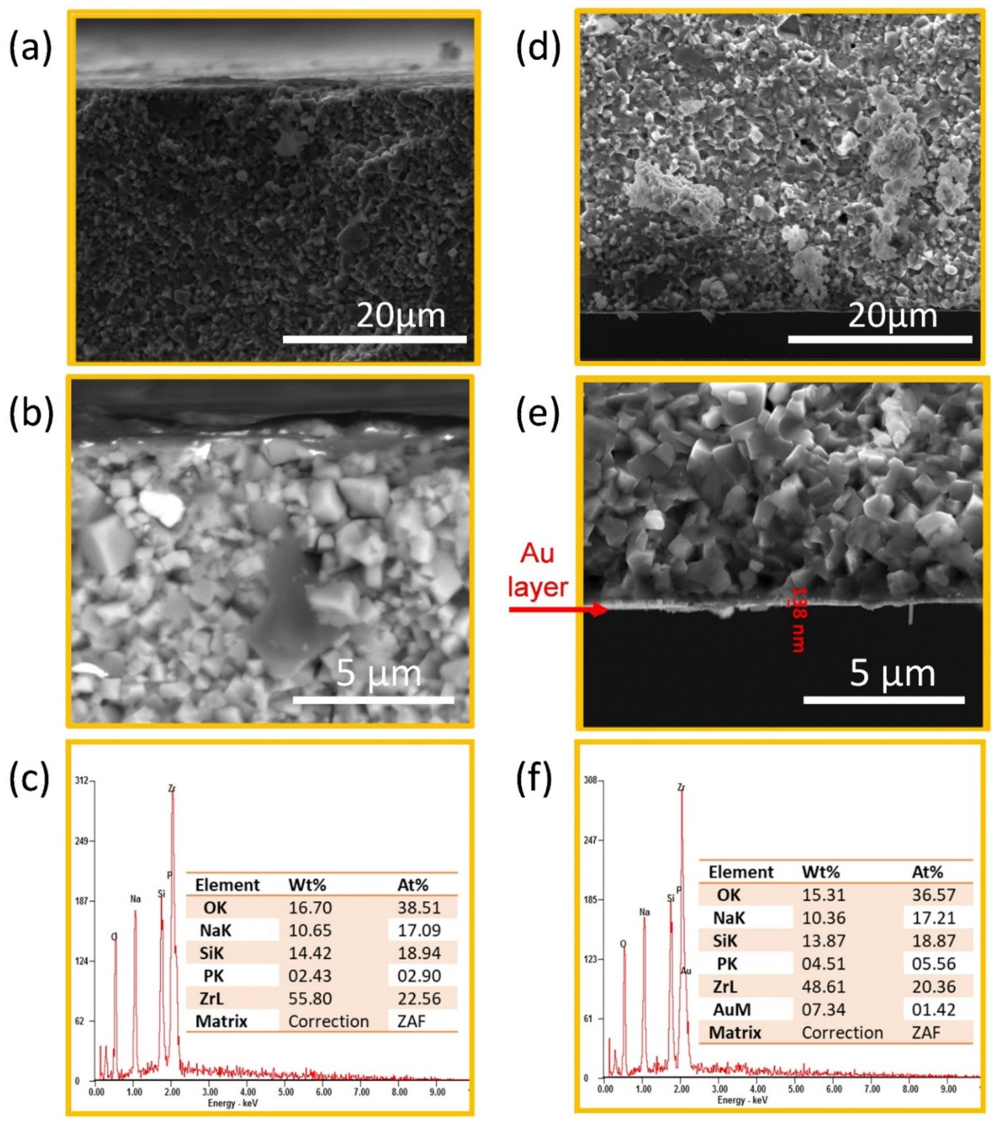
3.2. Symmetric Cell Evaluation

Figure 4a shows the EIS analysis of the fabricated symmetric cells: Na ||NZSP|| Na and Na ||Au-NZSP-Au|| Na. Both of the symmetric cells display two clear, different semicircles in the high- and low-frequency regions, corresponding to the bulk (from NZSP) and the charge-transfer resistance (between NZSP and Na metal).
The Na ||NZSP|| Na cell indicates a significant charge-transfer resistance of 2708 Ω cm2 (for either side), which may be ascribed to the poor sodium wettability of NZSP. Nevertheless, with the surface modification using the Au interlayer, the total area-specific resistance of the Na ||Au-NZSP-Au|| Na substantially decreased to 146 Ω cm2 (for either side). The impedance diminution was the result of the sodium alloying with gold when hot (80 °C) sodium was combined with Au-NZSP, enhancing the contact between sodium and NZSP, thereby providing a homogeneous sodium-ion flow. [50,56]
The interfacial resistance improvement was also examined via a galvanostatic sodium-stripping and -plating experiment. Initially, the cells were charged to plate sodium metal onto an NZSP solid electrolyte. Later, the cell was discharged to strip the sodium metal to bring out the kinetics of the cell. Figure 4b displays the voltage study of a Na ||NZSP|| Na cell periodically charged and discharged at 50 µA cm−2. The cell exhibited a noisy potential with a large voltage polarization of 0.1 V, indicating an irregular sodium-ion transport over the interface. After 30 h of cycling, the polarization suddenly increased due to the nonuniform current distribution arising from the loss of the electrolyte/Na-electrode contact commonly observed in solid electrolytes. This is attributable to the insufficient wettability and dearth of the interphase between Na and the solid electrolyte. [19,35,36,37] Therefore, a uniform sodium-ion-conducting buffer layer may be essential to stop sodium dendrite formation and induce a stable sodium-ion transport at the interface. In contrast, the symmetric cell with Au interlayer, Na||Au-NZSP-Au||Na (Figure 4c), charged and discharged for 10 min, from 25 to 200 µA cm−2, shows a voltage profile with uniform sodium-stripping/plating over an extended timeframe and without any increase in cell polarization. Furthermore, the Na ||Au-NZSP-Au|| Na cell was subjected to different current densities of 200, 240, and 320 µA cm−2 to examine the sodium-ion transport across the Na||Au-NZSP interface (Figure 4d), and it was found that the voltage hysteresis increased linearly with increasing current density. The enhanced interface allows for a stable sodium dissolution and deposition, suppressing the dendrite growth and ensuring that the Au interlayer helps in improving the wettability of NZSP with sodium, leading to a homogeneous sodium-ion flow. [45,46]
The schematic representation of the NZSP and Na metal interface is shown in Figure 5. For cases where no surface modification has been used (Figure 5a), the NZSP has inadequate physical contact with Na metal. In contrast, the ultrathin Au layer coats the NZSP surface with no interfacial void space (Figure 5b). Thus, the symmetric cell using Au interlayer showed appreciably lower interfacial resistance (146 Ω cm2) compared to that of the nonmodified (2708 Ω cm2), as is given in Figure 5c.
The ion-milled cross-sectional SEM of fresh Na ||NZSP and Na ||Au-NZSP interface is displayed in Figure 6. For the NZSP pellet without any Au-layer coating (Figure 6a), the interfacial gaps are more evident, indicating the poor wettability degree of NZSP. Furthermore, the formation of dendrites might be facile with the point contact (for example, a region between two or three grains connecting only with their end parts, leaving a gap in the center) at the interface where the grain boundaries will be penetrated easily, further enlarging the interval. The optical image of interface of Na ||NZSP|| Na after sodium-stripping/plating experiments at 50 µA cm−2 (Figure S1) enables the formation of sodium dark spots to be observed on the surface and in the cross-sectional area. To gain further insight, the region of the dark spot was subjected to a cross-sectional SEM analysis, which showed a dense region of dendrites growing via grain boundaries (Figure S2). The corresponding EDAX analysis also indicates a higher sodium contribution, which may be considered clear evidence for the dendritic growth. This drastic deterioration of the interface might be the reason for the poor plating and stripping observed for the Na ||NZSP|| Na symmetric cell in comparison to the Na ||Au-NZSP-Au|| Na symmetric cell. However, after modification with a gold interlayer (Figure 6b), the surface morphology of NZSP shows an enhanced physical contact at the interface, revealing an improved wettability of sodium with NZSP. Figure S3 depicts the cross-sectional morphology of the Na ||Au-NZSP-Au|| Na interface cycled at 100 µA cm−2, where, in this case, there is no evidence of dendritic growth. The elemental mappings based on the EDAX analysis showed the gold and sodium distributions on the surface. The surface of Au-coated NZSP appeared smoother, with improved wettability compared to Na ||NZSP|| Na, therefore delivering an efficacious contact area and reducing the low interfacial resistance and the voltage hysteresis.

3.3. Fabrication and Electrochemical Performance Evaluation of Na-Au||NZSP||PP-NFP

The compatibility of the Au interlayer and NZSP was further analyzed in a quasi-solid-state battery with NFP and Na metal as the cathode and anode, respectively. The room-temperature (25 °C) impedance measurement of a Na-Au||NZSP||PP-NFP cell (Figure 7a) comprised a large, high-frequency semicircle, corresponding to the charge-transfer resistance, and a low-frequency tail, which could be assigned to solid-state sodium-ion diffusion through NFP. The total interface resistance of the cell was found to be 1266 Ω cm2, corresponding to the summation of the cathode||electrolyte (i.e., NFP||NZSP) and the anode||electrolyte (i.e., Na||Au-NZSP) interfacial resistance. The charge and discharge cycle of the fabricated quasi-solid-state Na-Au||NZSP||PP-NFP battery was measured in the potential window of 1.5–4.0 V vs. Na+/Na at 50 μA cm−2 and 25 °C (Figure 7b). During the first discharge, the battery delivers a capacity ~100 mAh g−1 and maintains a good charge–discharge performance for 50 cycles. Figure 7c shows the Coulombic efficiency (CE) and capacity retention versus the cycle number of the Na-Au||NZSP||PP-NFP measured at 50 μA cm−2. Despite the large volume mismatch between end products (NaFePO4 and FePO4 [57]), the cathode material shows a high CE at the end of 50 cycles, with a discharge capacity of ~75 mAh g−1 and capacity retention of ∼80%. This decreased capacity observed with long cycling might be due to insufficient contact between the NZSP solid electrolyte and the NFP cathode. A rate capability test of the Na-Au||NZSP||PP-NFP cell was performed at 50, 100, and 150 μA cm−2 in the potential window of 1.5−4 V vs. Na+/Na (Figure 7d). At 50 μA cm−2, a discharge capacity of ~95 mAh g−1 was observed. Despite the significant increase in cycling rate, the cell still delivered discharge capacities of 68 mAh g−1 (100 μA cm−2) and 47 mAh g−1 (150 μA cm−2), with a CE of ~100%. After a fast discharge at 150 μA cm−2, the cell has been cycled at 50 μA cm−2 and the cell can recover the initial discharge capacity of 91 mAh g−1 and a CE of ∼100%. This demonstrated the efficacy of the technological approach described in this work.

4. Conclusions

The interfacial stability is a crucial factor for the configuration and operation of all solid-state batteries. This study illustrates an efficient process to enhance the poor sodium wettability and large polarization at the interface between the sodium anode and the NZSP solid electrolyte by means of a thin Au layer, which decreased the interfacial resistance from 2708 Ω cm2 to 146 Ω cm2. The symmetric cell, with a configuration of Na||NZSP||Na, displayed a fluctuating voltage profile due to the nonuniform Na+ flow leading to the formation of sodium dendrites. In contrast, a steady voltage profile was achieved by introducing a Au interlayer (i.e., for the Na ||Au-NZSP-Au|| Na symmetric cell). The development of a Na–Au alloy at the interface could assist with sodium-ion conduction and help to improve battery safety by repressing the sodium dendrite penetration. At 50 μA cm−2, the fabricated Na-Au||NZSP||PP-NFP battery displayed an initial discharge capacity of ~95 mAh g−1. At the end of 50 cycles, the cell demonstrated a capacity retention of ~80%, with a CE of 100%. This study reveals that proper interface modification using high-sodium-ion-conducting NZSP solid electrolytes opens opportunities for developing solid-state sodium batteries at RT with safe operations.

Supplementary Materials

The following supporting information can be downloaded at: https://www.mdpi.com/article/10.3390/batteries9010008/s1, Figure S1: Optical images of the dark spots that appeared in the cycled Na || NZSP pellet: (a,b) top surface, and (c,d) cross-sectional fracture surfaces; Figure S2: (a) Ion-milled cross-sectional SEM image showing Na || NZSP symmetric cell deterioration through dendrite growth after cycling. The topmost and the bottom part represents the ion milling stub (b-g) Elemental mapping on the interface morphology of Na || NZSP (h) energy-dispersive X-ray spectroscopy (EDX) patterns of Na || Au-NZSP interface; Figure S3: (a) Cross-sectional SEM image of Na || Au-NZSP interface after cycling with no traces of dendritic growth, (b) Elemental mapping of the interface morphology of Na || Au-NZSP, (c) energy dispersive X-ray spectroscopy (EDX) patterns of Na || Au-NZSP interface.

Author Contributions

Methodology, R.S., M.E. and Y.Z.; investigation, R.S., M.E. and Y.Z.; writing—original draft preparation, R.S., M.A. and M.G.; supervision, M.G.; project administration, M.G.; funding acquisition, M.G. All authors have read and agreed to the published version of the manuscript.

Funding

This present work is part of R&D&I projects PID2019-107468RB-C22 and PLEC2021-007929, funded by the Ministerio de Ciencia e Innovación, and CICe20, funded by the Basque Government.

Institutional Review Board Statement

Not applicable.

Informed Consent Statement

Not applicable.

Data Availability Statement

Not applicable.

Acknowledgments

The authors gratefully acknowledge Ainhoa Bustinza for her lab-work assistance.

Conflicts of Interest

The authors declare no conflict of interest.

References

  1. Sawicki, M.; Shaw, L. Advances and challenges of sodium ion batteries as post lithium ion batteries. RSC Adv. 2015, 5, 53129. [Google Scholar] [CrossRef]
  2. Kim, S.W.; Seo, D.H.; Ma, X.; Ceder, G.; Kang, K. Electrode Materials for Rechargeable Sodium-Ion Batteries: Potential Alternatives to Current Lithium-Ion Batteries. Adv. Energy Mater. 2012, 2, 710. [Google Scholar] [CrossRef]
  3. Palomares, V.; Serras, P.; Villaluenga, I.; Hueso, K.B.; Carretero-González, J.; Rojo, T. Na-ion batteries, recent advances and present challenges to become low-cost energy storage systems. Energy Environ. Sci. 2012, 5, 5884. [Google Scholar] [CrossRef]
  4. Slater, M.D.; Kim, D.; Lee, E.; Johnson, C. Sodium-Ion Batteries. Adv. Funct. Mater. 2013, 23, 947. [Google Scholar] [CrossRef]
  5. Hwang, J.Y.; Myung, S.T.; Sun, Y.K. Sodium-ion batteries: Present and future. Chem. Soc. Rev. 2017, 46, 3529. [Google Scholar] [CrossRef] [Green Version]
  6. Barpanda, P.; Chotard, J.N.; Recham, N.; Delacourt, C.; Ati, M.; Dupont, L.; Armand, M.; Tarascon, J.M. Structural, transport, and electrochemical investigation of novel AMSO4F (A = Na, Li; M = Fe, Co, Ni, Mn) metal fluorosulphates prepared using low temperature synthesis routes. Inorg. Chem. 2010, 49, 7401. [Google Scholar] [CrossRef]
  7. Plashnitsa, L.S.; Kobayashi, E.; Noguchi, Y.; Okada, S.; Yamaki, J.I. Performance of NASICON Symmetric Cell with Ionic Liquid Electrolyte. J. Electrochem. Soc. 2010, 157, A536. [Google Scholar] [CrossRef]
  8. Kim, H.; Park, I.; Seo, D.H.; Lee, S.; Kim, S.W.; Kwon, W.J.; Park, Y.U.; Kim, C.S.; Jeon, S.; Kang, K. New iron-based mixed-polyanion cathodes for lithium and sodium rechargeable batteries: Combined first principles calculations and experimental study. J. Am. Chem. Soc. 2012, 134, 10369. [Google Scholar] [CrossRef]
  9. Xiao, J.; Li, X.; Tang, K.; Wang, D.; Long, M.; Gao, H.; Chen, W.; Liu, C.; Liu, H.; Wang, G. Recent progress of emerging cathode materials for sodium ion batteries. Mater. Chem. Front. 2021, 5, 3735. [Google Scholar] [CrossRef]
  10. Wang, H.; Liao, X.Z.; Yang, Y.; Yan, X.; He, Y.S.; Ma, Z.F. Large-Scale Synthesis of NaNi1/3Fe1/3Mn1/3O2 as High Performance Cathode Materials for Sodium Ion Batteries. J. Electrochem. Soc. 2016, 3, A565. [Google Scholar] [CrossRef]
  11. Jian, Z.L.; Han, W.Z.; Lu, X.; Yang, H.X.; Hu, Y.S.; Zhou, J.; Zhou, Z.B.; Li, J.Q.; Chen, W.; Chen, D.; et al. Superior Electrochemical Performance and Storage Mechanism of Na3V2(PO4)3 Cathode for Room-Temperature Sodium-Ion Batteries. Adv. Energy Mater. 2013, 3, 156. [Google Scholar] [CrossRef]
  12. Senguttuvan, P.; Rousse, G.; Seznec, V.; Tarascon, J.M.; Palacin, M.R. Na2Ti3O7: Lowest Voltage Ever Reported Oxide Insertion Electrode for Sodium Ion Batteries. Chem. Mater. 2011, 23, 4109. [Google Scholar] [CrossRef]
  13. Zhang, Z.; Zhang, Q.; Shi, J.; Chu, S.Y.; Yu, X.; Xu, K.; Ge, M.; Yan, H.; Li, W.; Gu, L. A self-forming composite electrolyte for solid-state sodium battery with ultralong cycle life. Adv. Energy Mater. 2017, 7, 1601196. [Google Scholar] [CrossRef]
  14. Zhao, C.; Liu, L.; Qi, X.; Lu, Y.; Wu, F.; Zhao, J.; Yu, Y.; Hu, Y.S.; Chen, L. Solid-State Sodium Batteries. Adv. Energy Mater. 2018, 8, 1703012. [Google Scholar] [CrossRef]
  15. Kim, J.J.; Yoon, K.; Park, I.; Kang, K. Progress in the Development of Sodium-Ion Solid Electrolytes. Small Methods 2017, 1, 1700219. [Google Scholar] [CrossRef]
  16. Fan, L.; Wei, S.; Li, S.; Li, Q.; Lu, Y. Recent Progress of the Solid-State Electrolytes for High-Energy Metal-Based Batteries. Adv. Energy Mater. 2018, 8, 1702657. [Google Scholar] [CrossRef]
  17. Hou, H.; Xu, Q.; Pang, Y.; Li, L.; Wang, J.; Zhang, C.; Sun, C. Efficient Storing Energy Harvested by Triboelectric Nanogenerators Using a Safe and Durable All-Solid-State Sodium-Ion Battery. Adv. Sci. 2017, 4, 1700072. [Google Scholar] [CrossRef]
  18. Xu, L.; Li, J.; Liu, C.; Zou, G.; Hou, H.; Ji, X. Research Progress in Inorganic Solid-State Electrolytes for Sodium-Ion Batteries. Acta Phys.-Chim. Sin. 2020, 36, 1905013. [Google Scholar]
  19. Zhou, W.; Li, Y.; Xin, S.; Goodenough, J.B. Rechargeable Sodium All-Solid-State Battery. ACS Cent. Sci. 2017, 3, 52. [Google Scholar] [CrossRef]
  20. Kundu, D.; Talaie, E.; Duffort, V.; Nazar, L.F. The Emerging Chemistry of Sodium Ion Batteries for Electrochemical Energy Storage. Angew. Chem. Int. Ed. 2015, 54, 3431. [Google Scholar] [CrossRef]
  21. Lu, Y.; Li, L.; Zhang, Q.; Niu, Z.; Chen, J. Electrolyte and Interface Engineering for Solid-State Sodium Batteries. Joule 2018, 2, 1747. [Google Scholar] [CrossRef]
  22. Hong, H. Crystal structures and crystal chemistry in the system Na1+xZr2SixP3−xO12. Mater. Res. Bull. 1976, 11, 173. [Google Scholar] [CrossRef]
  23. Goodenough, J.B.; Hong, H.; Kafalas, J.A. Fast Na+-ion transport in skeleton structures. Mater. Res. Bull. 1976, 11, 203. [Google Scholar] [CrossRef]
  24. Von Alpen, U.; Bell, M.F.; Wichelhaus, W. Phase transition in nasicon (Na3Zr2Si2PO12). Mater. Res. Bull. 1979, 14, 1317. [Google Scholar] [CrossRef]
  25. Perthuis, H.; Colomban, P. Sol-gel Routes Leading to NASICON Ceramics. Ceram. Int. 1986, 12, 39. [Google Scholar] [CrossRef]
  26. Bohnke, O.; Ronchetti, S.; Mazza, D. Conductivity measurements on nasicon and nasicon-modified materials. Solid State Ion. 1999, 122, 127. [Google Scholar] [CrossRef]
  27. Niu, Y.; Yin, Y.X.; Guo, Y. Nonaqueous Sodium-Ion Full Cells: Status, Strategies, and Prospects. Small 2019, 15, 1900233. [Google Scholar] [CrossRef]
  28. Ruan, Y.; Guo, F.; Liu, J.; Song, S.; Jiang, N.; Cheng, B. Optimization of Na3Zr2Si2PO12 ceramic electrolyte and interface for high performance solid-state sodium battery. Ceram Int. 2019, 45, 1770. [Google Scholar] [CrossRef]
  29. Hou, W.; Guo, X.; Shen, X.; Amine, K.; Yu, H.; Lu, J. Solid electrolytes and interfaces in all-solid-state sodium batteries: Progress and perspective. Nano Energy 2018, 52, 279. [Google Scholar] [CrossRef]
  30. Huang, Y.; Zhao, L.; Li, L.; Xie, M.; Wu, F.; Chen, R. Electrolytes and Electrolyte/Electrode Interfaces in Sodium-Ion Batteries: From Scientific Research to Practical Application. Adv. Mater. 2019, 31, 1808393. [Google Scholar] [CrossRef]
  31. Ellis, B.L.; Nazar, L. Sodium and sodium-ion energy storage batteries. Curr. Opin. Solid State Mater. Sci. 2012, 16, 168. [Google Scholar] [CrossRef]
  32. Sumaletha, N.; Samuel, R.; Shantel, B.; Thangadurai, V. Sintering temperature, excess sodium, and phosphorous dependencies on morphology and ionic conductivity of NASICON Na3Zr2Si2PO12. Solid State Ion. 2019, 331, 22. [Google Scholar]
  33. Goodenough, J.B.; Singh, P.J. Review-Solid Electrolytes in Rechargeable Electrochemical Cells. Electrochem. Mater. 2015, 162, A2387. [Google Scholar] [CrossRef]
  34. Luntz, A.C.; Voss, J.; Reuter, K.J. Interfacial Challenges in Solid-State Li Ion Batteries. Phys. Chem. Lett. 2015, 6, 4599. [Google Scholar] [CrossRef] [PubMed] [Green Version]
  35. Gao, Z.; Yang, J.; Yuan, H.; Fu, H.; Li, Y.; Li, Y.; Ferber, T.; Guhl, C.; Sun, H.; Jaegermann, W.; et al. Stabilizing Na3Zr2Si2PO12/Na Interfacial Performance by Introducing a Clean and Na-Deficient Surface. Chem. Mater. 2020, 32, 3970. [Google Scholar] [CrossRef]
  36. Miao, X.; Di, H.; Ge, X.; Zhao, D.; Wang, P.; Wang, R.; Wang, C.; Yin, L. AlF3-modified anode-electrolyte interface for effective Na dendrites restriction in nasicon-based solid-state electrolyte. Energy Storage Mater. 2020, 30, 170. [Google Scholar] [CrossRef]
  37. Uchida, Y.; Hasegawa, G.; Shima, K.; Inada, M.; Enomoto, N.; Akamatsu, H.; Hayashi, K. Insights into Sodium Ion Transfer at the Na/NASICON Interface Improved by Uniaxial Compression. ACS Appl. Energy Mater. 2019, 2, 2913. [Google Scholar] [CrossRef]
  38. Yang, J.Y.; Xu, H.; Wu, J.; Gao, Z.; Hu, F.; Wei, Y.; Li, Y.; Liu, D.; Huang, Y.H. Improving Na/Na3Zr2Si2PO12 Interface via SnOx/Sn Film for High-Performance Solid-State Sodium Metal Batteries. Small Methods 2021, 5, 2100339. [Google Scholar] [CrossRef]
  39. He, M.; Cui, Z.; Chen, C.; Li, Y.; Guo, X. Formation of self-limited, stable and conductive interfaces between garnet electrolytes and lithium anodes for reversible lithium cycling in solid-state batteries. J. Mater. Chem. A 2018, 6, 11463. [Google Scholar] [CrossRef]
  40. Liu, B.; Zhang, L.; Xu, S.; McOwen, D.; Gong, Y.; Yang, C.; Pastel, G.; Xie, H.; Fu, K.; Dai, J.; et al. 3D lithium metal anodes hosted in asymmetric garnet frameworks toward high energy density batteries. Energy Storage Mater. 2018, 14, 376. [Google Scholar] [CrossRef]
  41. Fu, K.K.; Gong, Y.; Liu, B.; Zhu, Y.; Xu, S.; Yao, Y.; Luo, W.; Wang, C.; Lacey, S.D.; Dai, J.; et al. Toward garnet electrolyte–based Li metal batteries: An ultrathin, highly effective, artificial solid-state electrolyte/metallic Li interface. Sci. Adv. 2017, 3, e1601659. [Google Scholar] [CrossRef] [PubMed] [Green Version]
  42. Wang, C.; Gong, Y.; Liu, B.; Fu, K.; Yao, Y.; Hitz, E.; Li, Y.; Dai, J.; Xu, S.; Luo, W.; et al. Conformal, Nanoscale ZnO Surface Modification of Garnet-Based Solid-State Electrolyte for Lithium Metal Anodes. Nano Lett. 2017, 17, 565. [Google Scholar] [CrossRef] [PubMed]
  43. Han, X.; Gong, Y.; Fu, K.K.; He, X.; Hitz, G.T.; Dai, J.; Pearse, A.; Liu, B.; Wang, H.; Rubloff, G.; et al. Negating interfacial impedance in garnet-based solid-state Li metal batteries. Nat. Mater. 2017, 16, 572. [Google Scholar] [CrossRef] [PubMed]
  44. Luo, W.; Gong, Y.; Zhu, Y.; Li, Y.; Yao, Y.; Zhang, Y.; Fu, K.; Pastel, G.; Lin, C.F.; Mo, Y.; et al. Reducing Interfacial Resistance between Garnet-Structured Solid-State Electrolyte and Li-Metal Anode by a Germanium Layer. Adv. Mater. 2017, 29, 1606042. [Google Scholar] [CrossRef] [PubMed]
  45. Luo, W.; Gong, Y.; Zhu, Y.; Fu, K.K.; Dai, J.; Lacey, S.D.; Wang, C.; Liu, B.; Han, X.; Mo, Y.; et al. In Situ Neutron Depth Profiling of Lithium Metal–Garnet Interfaces for Solid State Batteries. J. Am. Chem. Soc. 2016, 138, 12258. [Google Scholar] [CrossRef]
  46. Tsai, C.L.; Roddatis, V.; Chandran, C.; Ma, Q.; Uhlenbruck, S.; Bram, M.; Heitjans, P.; Guillon, O. Li7La3Zr2O12 Interface Modification for Li Dendrite Prevention. ACS Appl. Mater. Interfaces 2016, 8, 10617. [Google Scholar] [CrossRef]
  47. Alexander, G.V.; Patra, S.; Raj, S.V.S.; Sugumar, M.; Din, M.; Muru-gan, R.J. Electrodes-electrolyte interfacial engineering for realizing room temperature lithium metal battery based on garnet structured solid fast Li+ conductors. Power Sources 2018, 396, 764. [Google Scholar] [CrossRef]
  48. Park, K.; Yu, B.-C.; Jung, J.-W.; Li, Y.; Zhou, W.; Gao, H.; Son, S.; Goodenough, J.B. Electrochemical Nature of the Cathode Interface for a Solid-State Lithium-Ion Battery: Interface between LiCoO2 and Garnet-Li7La3Zr2O12. Chem. Mater. 2016, 28, 8051. [Google Scholar] [CrossRef]
  49. Alexander, G.V.; Indu, M.S.; Kamakshy, S.; Murugan, R. Development of stable and conductive interface between garnet structured solid electrolyte and lithium metal anode for high performance solid-state battery. Electrochim. Acta 2020, 332, 135511. [Google Scholar] [CrossRef]
  50. Indu, M.S.; Alexander, G.V.; Deviannapoorani, C.; Murugan, R. Realization of room temperature lithium metal battery with high Li+ conductive lithium garnet solid electrolyte. Ceram. Int. 2019, 45, 22610. [Google Scholar] [CrossRef]
  51. Berlanga, C.; Monterrubio, I.; Armand, M.; Rojo, T.; Galceran, M.; Casas-Cabanas, M. Cost-effective synthesis of triphylite-NaFePO4 cathode: A zero-waste process. ACS Sustain. Chem. Eng. 2020, 8, 725–730. [Google Scholar] [CrossRef]
  52. Boilot, J.P.; Collin, G.; Colomban, P. Crystal structure of the true nasicon: Na3Zr2Si2PO12. Mater. Res. Bull. 1987, 5, 669. [Google Scholar] [CrossRef]
  53. Krok, F. Influence of sintering conditions on chemical composition of NASICON. Solid State Ionics. 1987, 24, 21. [Google Scholar] [CrossRef]
  54. Gordon, R.; Miller, G.; McEntire, B.; Beck, E.; Rasmussen, J. Fabrication and characterization of NASICON electrolytes. Solid State Ion. 1981, 3−4, 243. [Google Scholar] [CrossRef]
  55. Fuentes, R.O.; Figueiredo, F.M.; Marques, F.M.B.; Franco, J.I. Submicrometric NASICON Ceramics with Improved Electrical Conductivity Obtained from Mechanically Activated Precursors. J. Eur. Ceram. Soc. 2001, 21, 737. [Google Scholar] [CrossRef]
  56. Wakasugi, J.; Munakata, H.; Kanamura, K. Effect of Gold Layer on Interface Resistance between Lithium Metal Anode and Li6.25Al0.25La3Zr2O12 Solid Electrolyte. J. Electrochem. Soc. 2017, 164, A1022. [Google Scholar] [CrossRef]
  57. Galceran, M.; Saurel, D.; Acebedo, B.; Roddatis, V.; Martin, E.; Rojo, T.; Casas-Cabanas, M. The mechanism of NaFePO4 (de)sodiation determined by in situ X-ray diffraction. Phys. Chem. Chem. Phys. 2014, 16, 8837. [Google Scholar] [CrossRef]
Figure 1. (a) Le Bail refinement of the PXRD patterns of Na3Zr2Si2PO12 heated at 1230 °C for 12 h. (b) Impedance plot of Au||NZSP||Au assessed at 25 °C; (c) Arrhenius plot of NZSP measured in temperature range of 25–200 °C.
Batteries 09 00008 g001
Figure 2. Cross-sectional SEM morphology and EDX patterns of (ac) a Na3Zr2Si2PO12 pellet sintered at 1230 °C. (df) Na3Zr2Si2PO12 pellet showing the gold interlayer.
Batteries 09 00008 g002
Figure 3. AFM topography images of a gold-coated NZSP pellet are shown in both two- and three-dimensional views. The scanning area of the image (a) and its corresponding 3D image (b) are ~4 µm × ~4 µm. Zoomed-in images (c,d) correspond to a scanning area of about 1 µm × 1 µm.
Batteries 09 00008 g003
Figure 4. (a) Impedance plot of the symmetric cells Na ||NZSP|| Na and Na ||Au-NZSP-Au|| Na; (b) sodium-stripping/plating profile of Na ||NZSP|| Na at 50 µA cm−2; (c) sodium-stripping/plating of Na ||Au-NZSP-Au|| Na with an increasing current density ranging between 25 and 200 µA cm−2; (d) voltage profile at higher current densities of 200, 240, and 320 µA cm−2 for Na ||Au-NZSP-Au|| Na. All the measurements were performed at 25 °C.
Batteries 09 00008 g004
Figure 5. Schematic representation showing (a) a limited contact between the NZSP and Na metal, leading to huge interfacial resistance and (b) the better wettability of Au-NZSP, substantially enhanced through a Au interlayer, where the Na-Au alloy plays as a Na+ conducting layer. (c) Comparison of the Na||NZSP interface-area-specific resistance (IASR), both with and without the Au interlayer.
Batteries 09 00008 g005
Figure 6. Ion-milled cross-sectional SEM of (a) a fresh Na||NZSP cell exposing the poor wettability between the sodium and NZSP and (b) a fresh Na||Au-NZSP cell interface revealing enhanced sodium wettability with almost no interfacial gaps.
Batteries 09 00008 g006
Figure 7. (a) Impedance plot of Na-Au||NZSP||PP-NFP; (b) charge–discharge curve of the Na-Au||NZSP||PP-NFP cell at 50 μA cm−2; (c) cycling performance and Coulombic efficiency of the Na-Au||NZSP||PP-NFP at 50 μA cm−2; and (d) rate capability test of the Na-Au||NZSP||PP-NFP cell at various current densities. All the measurements were performed at 25 °C.
Batteries 09 00008 g007
Disclaimer/Publisher’s Note: The statements, opinions and data contained in all publications are solely those of the individual author(s) and contributor(s) and not of MDPI and/or the editor(s). MDPI and/or the editor(s) disclaim responsibility for any injury to people or property resulting from any ideas, methods, instructions or products referred to in the content.

