
Improving Cycle Life of Silicon-Dominant Anodes Based on Microscale Silicon Particles under Partial Lithiation

Abstract
1. Introduction
2. Materials and Methods
2.1. Material Preparation
2.1.1. Materials
2.1.2. Preparation of Silicon Microparticles (CLM00001)
2.1.3. Preparation of Carbon Coated Silicon Microparticles (CLM00007)
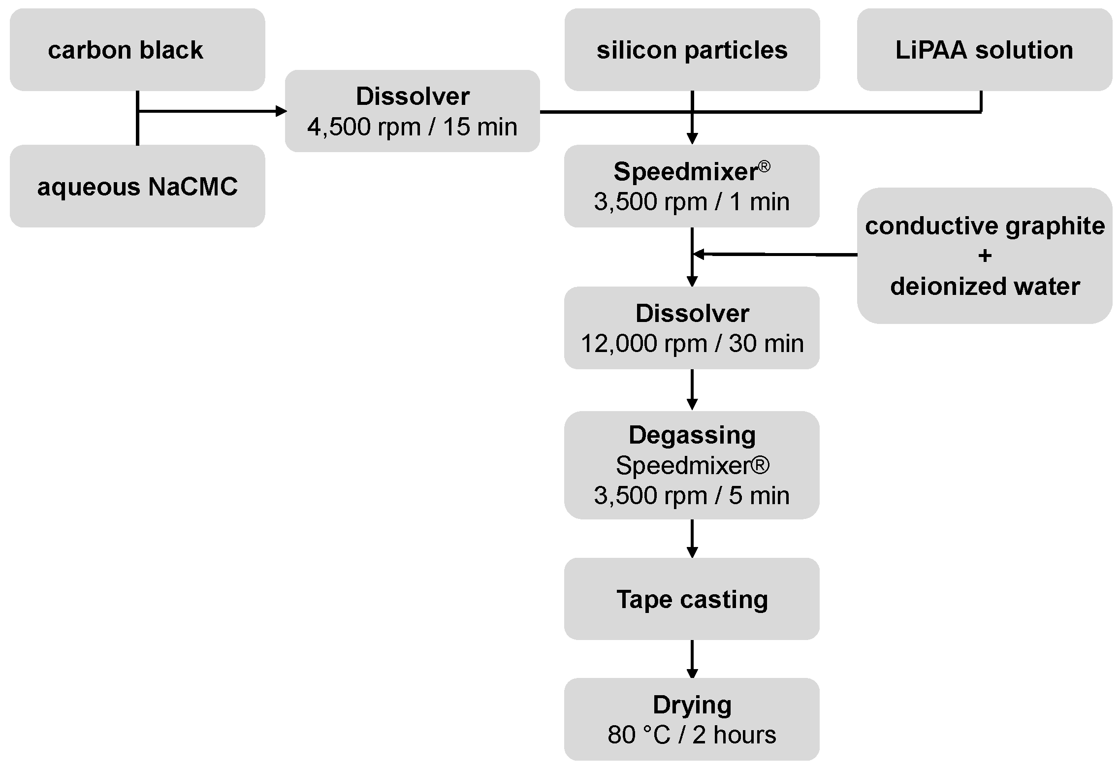
2.1.4. Anode Preparation Using Silicon Microparticles
2.1.5. Post-Treatment with LiNO3
2.2. Material Testing
2.2.1. Full Cell Measurement
2.2.2. Prelithiation of CLM00001- and CLM00007-Containing Anodes
3. Results and Discussion
4. Conclusions
Author Contributions
Funding
Data Availability Statement
Conflicts of Interest
References
- Kasavajjula, U.; Wang, C.; Appleby, A.J. Nano-and bulk-silicon-based insertion anodes for lithium-ion secondary cells. J. Power Sources 2007, 163, 1003. [Google Scholar] [CrossRef]
- Su, X.; Wu, Q.; Li, J.; Xiao, X.; Lott, A.; Lu, W.; Sheldon, B.W.; Wu, J. Silicon-Based Nanomaterials for Lithium-Ion Batteries: A Review. Adv. Energy Mater. 2014, 4, 1300882. [Google Scholar] [CrossRef]
- Obrovac, M.N.; Chevrier, V.L. Alloy Negative Electrodes for Li-Ion Batteries. Chem. Rev. 2014, 114, 11444. [Google Scholar] [CrossRef] [PubMed]
- Jin, Y.; Zhu, B.; Lu, Z.; Liu, N.; Zhu, J. Challenges and Recent Progress in the Development of Si Anodes for Lithium-Ion Battery. Adv. Energy Mater. 2017, 7, 1700715. [Google Scholar] [CrossRef]
- Graf, M.; Berg, C.; Bernhard, R.; Haufe, S.; Pfeiffer, J.; Gasteiger, H.A. Effect and Progress of the Amorphization Process for Microscale Silicon Particles under Partial Lithiation as Active Material in Lithium-Ion Batteries. J. Electrochem. Soc. 2022, 169, 020536. [Google Scholar] [CrossRef]
- Gonzalez, J.; Sun, K.; Huang, M.; Lambros, J.; Dillon, S.; Chasiotis, I. Three dimensional studies of particle failure in silicon based composite electrodes for lithium ion batteries. J. Power Sources 2014, 269, 334. [Google Scholar] [CrossRef]
- Liu, X.H.; Zhong, L.; Huang, S.; Mao, S.X.; Zhu, T.; Huang, J.Y. Size-Dependent Fracture of Silicon Nanoparticles during Lithiation. ACS Nano 2012, 6, 1522. [Google Scholar] [CrossRef] [PubMed]
- Luo, F.; Liu, B.; Zheng, J.; Chu, G.; Zhong, K.; Li, H.; Huang, X.; Chen, L. Nano-silicon/carbon composite anode materials towards practical application for next generation Li-ion batteries. J. Electrochem. Soc. 2015, 162, A2509. [Google Scholar] [CrossRef]
- Marom, S.F.A.R.; Leifer, N.; Jacob, D.; Aurbach, D. A review of advanced and practical lithium battery materials. J. Mater. Chem. 2011, 21, 9938. [Google Scholar] [CrossRef]
- Peled, E.; Menkin, S. SEI: Past, present and future. J. Electrochem. Soc. 2017, 164, A1703. [Google Scholar] [CrossRef]
- Goriparti, S.; Miele, E.; De Angelis, F.; Di Fabrizio, E.; Zaccaria, R.P.; Capiglia, C. Review on recent progress of nanostructured anode materials for Li-ion batteries. J. Power Sources 2014, 257, 421. [Google Scholar] [CrossRef]
- Takezawa, H.; Iwamoto, K.; Ito, S.; Yoshizawa, H. Electrochemical behaviors of nonstoichiometric silicon suboxides (SiOx) film prepared by reactive evaporation for lithium rechargeable batteries. J. Power Sources 2013, 244, 149. [Google Scholar] [CrossRef]
- Chevrier, V.L.; Liu, L.; Le, D.B.; Lund, J.; Molla, B.; Reimer, K.; Krause, L.J.; Jensen, L.D.; Figgemeier, E.; Eberman, K.W. Evaluating Si-based materials for Li-ion batteries in commercially relevant negative electrodes. J. Electrochem. Soc. 2014, 161, A783. [Google Scholar] [CrossRef]
- Heist, A.; Piper, D.M.; Evans, T.; Kim, S.C.; Han, S.S.; Oh, K.H.; Lee, S.-H. Self-Contained Fragmentation and Interfacial Stability in Crude Micron-Silicon Anodes. J. Electrochem. Soc. 2018, 165, A244. [Google Scholar] [CrossRef]
- Kim, H.; Han, B.; Choo, J.; Cho, J. Three-dimensional porous silicon particles for use in high-performance lithium secondary batteries. Angew. Chem. Int. Ed. 2008, 120, 10305. [Google Scholar] [CrossRef]
- Wang, C.; Chui, Y.-S.; Ma, R.; Wong, T.; Ren, J.-G.; Wu, Q.-H.; Chen, X.; Zhang, W. A three-dimensional graphene scaffold supported thin film silicon anode for lithium-ion batteries. J. Mater. Chem. A 2013, 1, 10092. [Google Scholar] [CrossRef]
- Zuo, X.; Zhu, J.; Müller-Buschbaum, P.; Cheng, Y.-J. Silicon based lithium-ion battery anodes: A chronicle perspective review. Nano Energy 2017, 31, 113. [Google Scholar] [CrossRef]
- Müller, V.; Bernhard, R.; Wegener, J.; Pfeiffer, J.; Rössler, S.; Scurtu, R.; Memm, M.; Danzer, M.A.; Wohlfahrt-Mehrens, M. Evaluation of Scalable Porous Si-Rich Si/C Composites with Low Volume Expansion in Coin Cells to Prismatic Cell Formats. Energy Technol. 2020, 8, 2000217. [Google Scholar] [CrossRef]
- Obrovac, M.N.; Krause, L.J. Reversible Cycling of Crystalline Silicon Powder. J. Electrochem. Soc. 2007, 154, A103. [Google Scholar] [CrossRef]
- Nguyen, B.P.N.; Chazelle, S.; Cerbelaud, M.; Porcher, W.; Lestriez, B. Manufacturing of industry-relevant silicon negative composite electrodes for lithium ion-cells. J. Power Sources 2014, 262, 112. [Google Scholar] [CrossRef]
- Beattie, S.D.; Loveridge, M.J.; Lain, M.J.; Ferrari, S.; Polzin, B.J.; Bhagat, R.; Dashwood, R. Understanding capacity fade in silicon based electrodes for lithium-ion batteries using three electrode cells and upper cut-off voltage studies. J. Power Sources 2016, 302, 426. [Google Scholar] [CrossRef]
- Jantke, D.; Bernhard, R.; Hanelt, E.; Buhrmester, T.; Pfeiffer, J.; Haufe, S. Silicon-Dominant Anodes Based on Microscale Silicon Particles under Partial Lithiation with High Capacity and Cycle Stability. J. Electrochem. Soc. 2019, 166, A3881. [Google Scholar] [CrossRef]
- Haufe, S. Siliciumpartikel enthaltende Anodenmaterialien für Lithium-Ionen-Batterien. Patent. EP 3335262 B1, 28 July 2016. [Google Scholar]
- Wagner, N.P.; Tron, A.; Tolchard, J.R.; Noia, G.; Bellmann, M.P. Silicon anodes for lithium-ion batteries produced from recovered kerf powders. J. Power Sources 2019, 414, 486. [Google Scholar] [CrossRef]
- Haufe, S.; Bernhard, R. Pfeiffer, Revealing the Failure Mechanism of Partially Lithiated Silicon-Dominant Anodes Based on Microscale Silicon Particles. J. Electrochem. Soc. 2021, 168, 080531. [Google Scholar] [CrossRef]
- Zhang, S.; Andreas, N.S.; Li, R.; Zhang, N.; Sun, C.; Lu, D.; Gao, T.; Chen, L.; Fan, X. Mitigating irreversible capacity loss for higher-energy lithium batteries. Energy Storage Mater. 2022, 48, 44. [Google Scholar] [CrossRef]
- Buchberger, I.; Jantke, D.; Haufe, S. Lithium Ion. Batteries. Patent WO 2020211938 A1, 17 April 2019. [Google Scholar]
- Nguyen, C.C.; Yoon, T.; Seo, D.M.; Guduru, P.; Lucht, B.L. Systematic Investigation of Binders for Silicon Anodes: Interactions of Binder with Silicon Particles and Electrolytes and Effects of Binders on Solid Electrolyte Interphase Formation. ACS Appl. Mater. Interfaces 2016, 8, 12211. [Google Scholar] [CrossRef]
- Jung, R.; Metzger, M.; Haering, D.; Solchenbach, S.; Marino, C.; Tsiouvaras, N.; Stinner, C.; Gasteiger, H.A. Consumption of fluoroethylene carbonate (FEC) on Si-C composite electrodes for Li-ion batteries. J. Electrochem. Soc. 2016, 163, A1705. [Google Scholar] [CrossRef]
- Bernhard, R.; Haufe, S.; Ege, M. Lithium Ion. Batteries. Patent WO 2020233799 A1, 21 May 2019. [Google Scholar]
- Holtstiege, F.; Bärmann, P.; Nölle, R.; Winter, M.; Placke, T. Pre-lithiation strategies for rechargeable energy storage technologies: Concepts, promises and challenges. Batteries 2018, 4, 4. [Google Scholar] [CrossRef]
- Xin, C.; Gao, J.; Luo, R.; Zhou, W. Prelithiation Reagents and Strategies on High Energy Lithium-Ion Batteries. Chem. Eur. J. 2022, 28, e202104282. [Google Scholar] [CrossRef]
- Huang, Z.; Deng, Z.; Zhong, Y.; Xu, M.; Li, S.; Liu, X.; Huang, K.; Shen, Y.; Huang, Y. Progress and challenges of prelithiation technology for lithium-ion battery. Carbon Energy 2022, 4, 1107. [Google Scholar] [CrossRef]
- Dose, W.M.; Johnson, C.S. Cathode pre-lithiation/sodiation for next-generation batteries. Curr. Opin. Electrochem. 2022, 31, 100827. [Google Scholar] [CrossRef]
- Chevrier, V.L.; Liu, L.; Wohl, R.; Chandrasoma, A.; Vega, J.A.; Eberman, K.W.; Figgemeier, E. Design and Testing of Prelithiated Full Cells with High Silicon Content. J. Electrochem. Soc. 2018, 165, A1129. [Google Scholar] [CrossRef]
- Dimov, N.; Kugino, S.; Yoshio, M. Carbon-coated silicon as anode material for lithium ion batteries: Advantages and limitations. Electrochim. Acta 2003, 48, 1579. [Google Scholar] [CrossRef]
- Wegener, J.; Haufe, S.; Stohrer, J. Carbon-Coated Silicon Particles for Lithium Ion Batteries. EP 3535793 B1, 11 January 2017. [Google Scholar]
- Li, Y.; Yan, K.; Lee, H.-W.; Lu, Z.; Liu, N.; Cui, Y. Growth of conformal graphene cages on micrometre-sized silicon particles as stable battery anodes. Nat. Energy 2016, 1, 15029. [Google Scholar] [CrossRef]
- Lu, Z.; Liu, N.; Lee, H.-W.; Zhao, J.; Li, W.; Li, Y.; Cui, Y. Nonfilling Carbon Coating of Porous Silicon Micrometer-Sized Particles for High-Performance Lithium Battery Anodes. ACS Nano 2015, 9, 2540. [Google Scholar] [CrossRef] [PubMed]
- Graf, M.; Reuter, L.; Qian, S.; Calmus, T.; Ghamlouche, A.; Maibach, J.; Bernhard, R.; Gasteiger, H.A. Understanding the Effect of Lithium Nitrate as Additive in Carbonate Based Electrolytes for Silicon Anodes. In ECS Meeting Abstracts; IOP Publishing: Bristol, UK, 2021. [Google Scholar] [CrossRef]
- Stearns, L.A.; Gryko, J.; Diefenbacher, J.; Ramachandran, G.K.; McMillan, P.F. Lithium monosilicide (LiSi), a low-dimensional silicon-based material prepared by high pressure synthesis: NMR and vibrational spectroscopy and electrical properties characterization. J. Solid State Chem. 2003, 173, 251. [Google Scholar] [CrossRef]


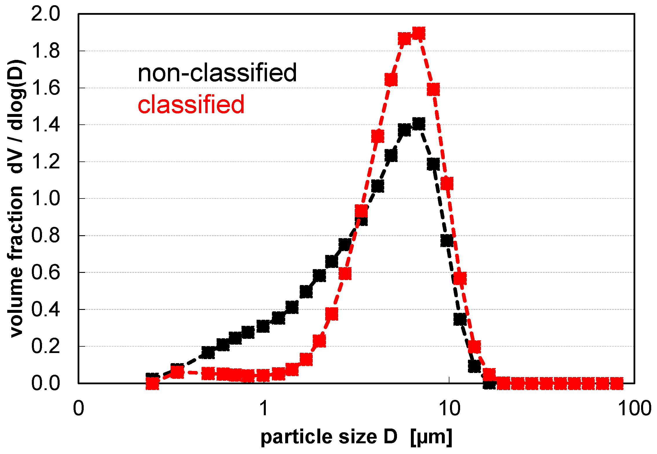
| d10 in µm | d50 in µm | d90 in µm | Span = (d90−d10)/d50 | BET in m2 g−1 | |
|---|---|---|---|---|---|
| Standard PSD | 0.83 | 4.35 | 9.31 | 1.95 | 2.79 |
| Air classified PSD | 2.60 | 5.67 | 9.90 | 1.29 | 1.48 |
| Carbon in wt. % | d10 in µm | d50 in µm | d90 in µm | Span = (d90−d10)/d50 | Density in g cm−3 |
|---|---|---|---|---|---|
| 0.0 | 0.83 | 4.35 | 9.31 | 1.95 | 0.95 |
| 2.3 | 1.79 | 6.46 | 14.02 | 1.89 | 0.84 |
| 4.0 | 2.82 | 7.63 | 15.97 | 1.72 | 0.81 |
| 5.7 | 3.03 | 8.51 | 17.86 | 1.74 | 0.75 |
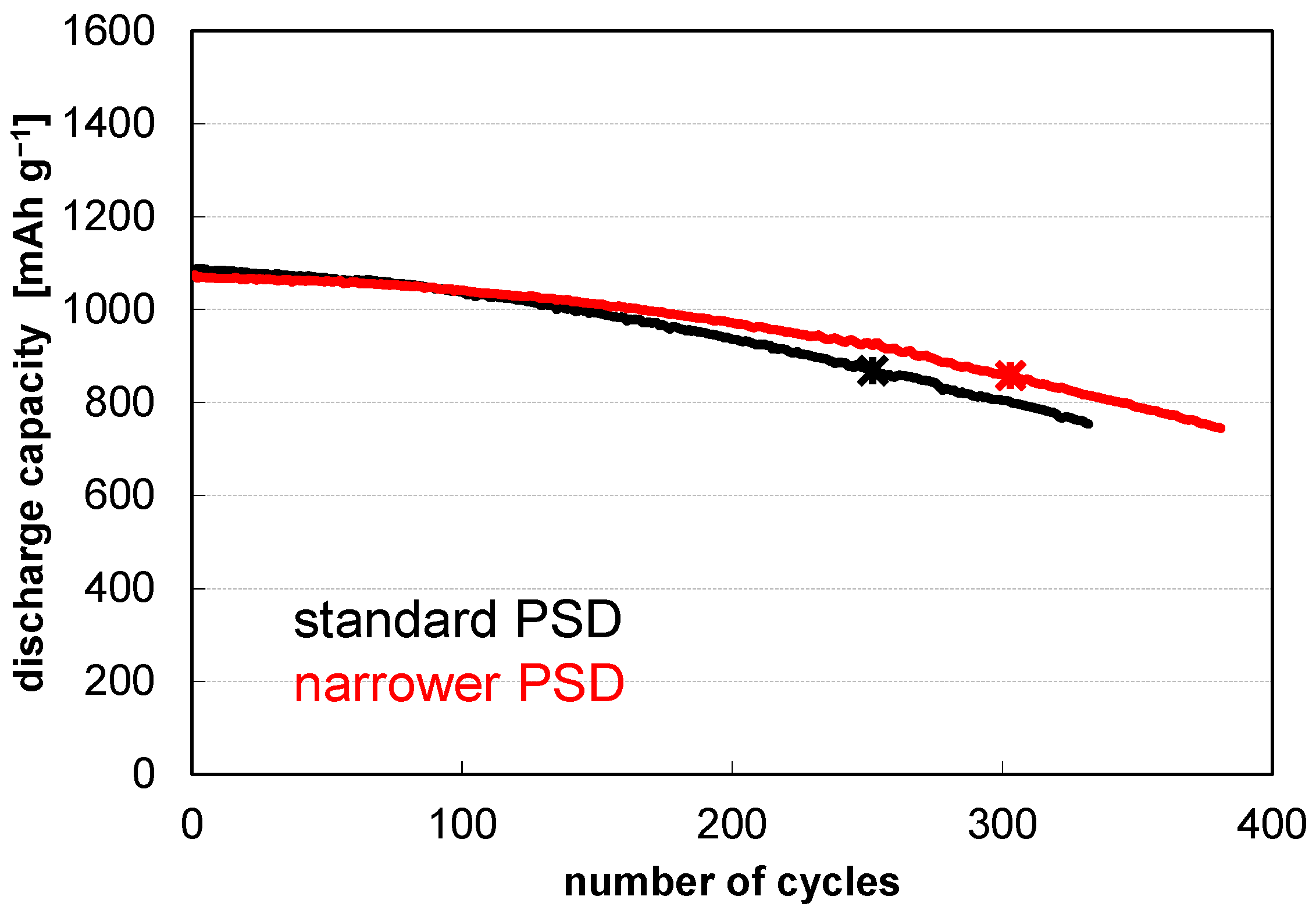
| Fines Removal | Carbon Coating | LiNO3 Treatment | Pre-Lithiation | Cycles @80% Retention |
|---|---|---|---|---|
| -- | -- | -- | -- | 249 ± 04‖252 |
| + | -- | -- | -- | 292 ± 11‖303 |
| -- | + | -- | -- | 281 ± 11‖289 |
| -- | -- | + | -- | 311 ± 05‖316 |
| -- | -- | -- | + | 405 ± 15‖420 |
| + | -- | -- | + | 467 ± 18‖490 |
| -- | + | -- | + | 513 ± 19‖531 |
| -- | -- | + | + | 411 ± 42‖439 |
| + | + | -- | + | 566 ± 32‖603 |
| + | + | + | + | 578 ± 29‖607 |
Disclaimer/Publisher’s Note: The statements, opinions and data contained in all publications are solely those of the individual author(s) and contributor(s) and not of MDPI and/or the editor(s). MDPI and/or the editor(s) disclaim responsibility for any injury to people or property resulting from any ideas, methods, instructions or products referred to in the content. |
© 2023 by the authors. Licensee MDPI, Basel, Switzerland. This article is an open access article distributed under the terms and conditions of the Creative Commons Attribution (CC BY) license (https://creativecommons.org/licenses/by/4.0/).
Share and Cite
Haufe, S.; Ranninger, J.; Bernhard, R.; Buchberger, I.; Hanelt, E. Improving Cycle Life of Silicon-Dominant Anodes Based on Microscale Silicon Particles under Partial Lithiation. Batteries 2023, 9, 58. https://doi.org/10.3390/batteries9010058
Haufe S, Ranninger J, Bernhard R, Buchberger I, Hanelt E. Improving Cycle Life of Silicon-Dominant Anodes Based on Microscale Silicon Particles under Partial Lithiation. Batteries. 2023; 9(1):58. https://doi.org/10.3390/batteries9010058
Chicago/Turabian StyleHaufe, Stefan, Johanna Ranninger, Rebecca Bernhard, Irmgard Buchberger, and Eckhard Hanelt. 2023. "Improving Cycle Life of Silicon-Dominant Anodes Based on Microscale Silicon Particles under Partial Lithiation" Batteries 9, no. 1: 58. https://doi.org/10.3390/batteries9010058
APA StyleHaufe, S., Ranninger, J., Bernhard, R., Buchberger, I., & Hanelt, E. (2023). Improving Cycle Life of Silicon-Dominant Anodes Based on Microscale Silicon Particles under Partial Lithiation. Batteries, 9(1), 58. https://doi.org/10.3390/batteries9010058