Article

Effect of Vinylene Carbonate Electrolyte Additive on the Process of Insertion/Extraction of Na into Ge Microrods Formed by Electrodeposition

by
Egor A. Lebedev
1,*,
Ilya M. Gavrilin
1,2,*,
Yulia O. Kudryashova
2,
Irina K. Martynova
1,
Roman L. Volkov
3,
Tatiana L. Kulova
2,
Alexander M. Skundin
2,
Nikolay I. Borgardt
3 and
Sergey A. Gavrilov
1
1
Institute of Advanced Materials and Technologies, National Research University of Electronic Technology—MIET, Shokin Square, 124498 Moscow, Russia
2
Frumkin Institute of Physical Chemistry and Electrochemistry, Leninsky Prospect, 119071 Moscow, Russia
3
Institute of Physics and Applied Mathematics, National Research University of Electronic Technology—MIET, Shokin Square, 124498 Moscow, Russia
*
Authors to whom correspondence should be addressed.
Batteries 2022, 8(9), 109; https://doi.org/10.3390/batteries8090109
Submission received: 31 July 2022 / Revised: 24 August 2022 / Accepted: 30 August 2022 / Published: 2 September 2022
(This article belongs to the Section Battery Modelling, Simulation, Management and Application)

Abstract

:
Layers of germanium (Ge) microrods with a core–shell structure on titanium foils were grown by a metal-assisted electrochemical reduction of germanium oxide in aqueous electrolytes. The structural properties and composition of the germanium microrods were studied by means of scanning and transmission electron microscopy. Electrochemical studies of germanium nanowires were carried out by impedance spectroscopy and cyclic voltammetry. The results showed that the addition of vinylene carbonate (VC) in the electrolyte significantly reduced the irreversible capacity during the first charge/discharge cycles and increased the long-term cycling stability of the Ge microrods. The obtained results will benefit the further design of Ge microrods-based anodes that are formed by simple electrochemical deposition.

1. Introduction

Sodium-ion batteries (SIB) are promising power sources, as their electrochemical characteristics are comparable to those of lithium-ion batteries (LIB) [1,2,3,4,5]. In addition, the availability of sodium-containing raw materials is much greater than that of lithium-containing materials. In recent years, various types of materials, including metal oxides, sodium metals, alloying types of materials, phosphorus materials, and carbonaceous materials have been actively investigated [6,7,8,9,10,11,12,13,14,15]. Among the promising materials for the negative electrode (anode) of a sodium-ion battery (SIB) are materials based on germanium (Ge). For example, germanium can form alloys with sodium (Na) for the composition of Na3Ge [16], which corresponds to the theoretical specific capacity of germanium, 1107 mAh/g. However, theoretical and experimental studies have found that crystalline Ge is not very effective in SIBs [17,18]. Kohandehghan et al. [18] showed that the preliminary amorphization of Ge nanowires promotes reversible Na insertion, up to 450 mAh/g. Gavrilin et al. [19] described Ge nanostructures that were cathodically deposited upon indium seeds and reported 590 mAh/g.
The Ge nanostructures described in [19] have a core–shell structure that is related to the deposition temperature [20]. It is the core–shell structure that determines the features of reversible sodium insertion. However, like other structures that have been studied, such as the anode materials in SIBs, these structures are susceptible to degradation during prolonged cycling. This degradation is usually associated with the formation of a passive film on the surface of the electrodes. Compared with LIBs, the passive film formed in sodium-based electrolytes are often considered less stable, due to the higher solubility of the components of the layer [21,22,23,24].
The use of electrolyte additives is a widely used strategy for the modification of passive film [25]. Vinylene carbonate (VC) is an effective electrolyte additive [26,27,28,29,30,31]. However, there are no data in the literature on the effect of VC on the electrochemical characteristics of germanium with a core–shell structure during the insertion/extraction of sodium ions. This work is the first to study the effect of adding vinylene carbonate to the electrolyte on the electrochemical characteristics of germanium during the insertion/extraction of sodium ions into Ge samples that were obtained by cathodic reduction from aqueous GeO2 solutions.

2. Results

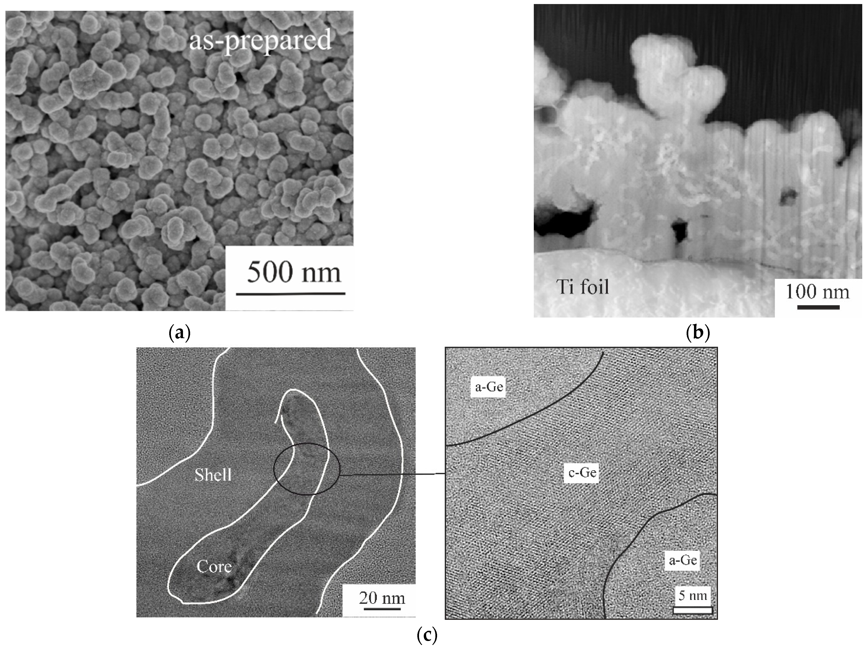
2.1. Morphological and Physical Studies of Ge Samples before Sodium Insertion/Extraction

Figure 1 shows the morphology and structure of the Ge microrods with a core–shell structure that were obtained by cathodic reduction from aqueous GeO2 solutions before the Na insertion/extraction process.
The morphology of Ge microrods with a core–shell structure can be seen in Figure 1a. Figure 1b shows the image obtained by transmission scanning electron microscopy (STEM). The STEM image (Figure 1b) shows Ge microrods with all sides surrounded by a shell that is approximately 50 nm thick, in which there are a large number of nanopores with sizes from 1 nm to 2 nm. Figure 1c shows the core–shell structure of Ge microrods with atomic resolution; core has a polycrystalline structure containing many twins and stacking faults. The porous shell around Ge microrods is amorphous germanium. As shown by Gavrilin et al. [20], this shell also contains a small portion of amorphous oxides (hydroxides) of germanium.

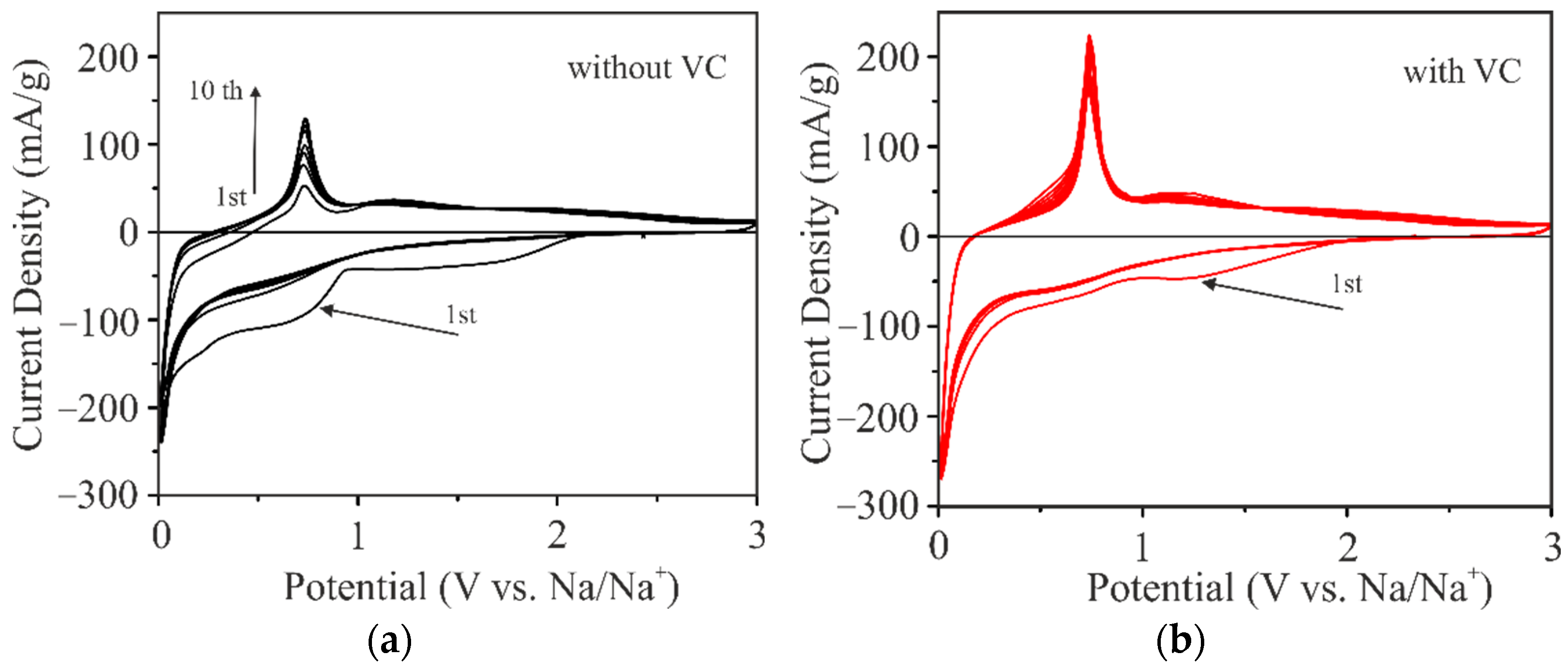
2.2. Electrochemical Studies of Sodium Insertion/Extraction

Figure 2 shows the cyclic voltammograms (CVs) for the sodium insertion/extraction process, with a potential scan rate 0.1 mV/s.
As can be seen, the addition of VC in the electrolyte influences the shape of the CVs at the first cycle. In the case of the VC-free electrolyte, the cathode branches of the CVs display two large and wide cathodic peaks in the potential range 1.5 V to 0.6 V and one pronounced peak at 0.03 V. The reverse anode branches contain two weak peaks at 0.7 V and 1.2 V. The first anode peak could be attributed to sodium extraction, and it corresponds to the cathode peak at 0.03 V [18,19]. The second anode peak could be explained by the possible oxidation of the products that are formed after sodium insertion.
It is worth noting that the anode peak at 0.7 V increased from the first to the fourth cycles. In other words, the discharge capacity increased upon initial cycling. Thereafter, up to the tenth cycle, this peak became more pronounced, which indicated stabilization of the discharge capacity. In turn, the cathode peak at 0.6 V was less pronounced than it was in the first cycle. At the same time, in the VC-containing electrolyte, the well-pronounced cathode peak at 0.03 V and corresponding anode peak at 0.7 V were already revealed at the first cycle. In addition, the cathode peak at 0.6 V disappeared in the VC-containing electrolyte.

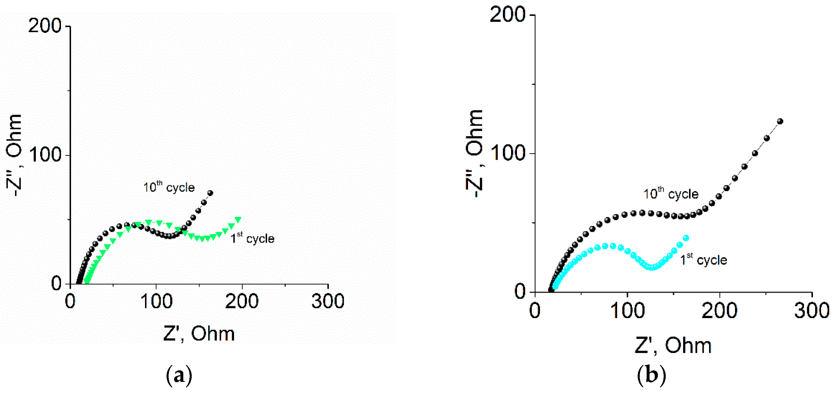
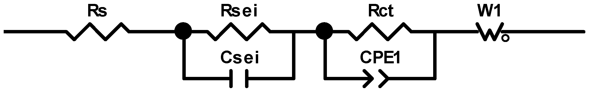
2.3. Impedance Measurements of Samples

Figure 3 shows the electrochemical impedance spectra of Ge microrods, recorded at room temperature for the first and tenth cycles in the with-VC and without-VC electrolyte solutions, respectively. Impedance was recorded after cathodic polarization, i.e., in the state of complete nanocrystals of germanium sodiation and solid electrolyte film formation on their surface.
The impedance spectra of all of the samples formed semicircles at high and medium frequencies and turned into straight lines at low frequencies. As the cycling progressed, the shape of the spectrum for the electrode in the without-VC electrolyte solution changed; specifically, the semicircle in the region of the high and medium frequencies decreased in diameter, which may have indicated a decrease in the passive film resistance and charge transfer resistance. The addition of VC led to a decrease in the diameter of the semicircle of the impedance spectrum in the first cycle, compared with that for the electrolyte without VC, which indicated a decrease in the passive film resistance and charge transfer resistance. However, further cycling resulted in a change in the spectrum shape, i.e., a “degradation” of the semicircle and an increase in total impedance.
To simulate the impedance spectra, an equivalent circuit, as shown in Figure 4, was proposed in our previous work [32].
In Figure 4, the element Rs relates to an electrolyte resistance, Rsei is the sei resistance, Csei is the capacitance of the sei, Rct is the charge transfer resistance, CPE is an element with a constant phase shift, and W1 is the Warburg impedance reflecting sodium diffusion in germanium. The calculated parameters of the equivalent circuit are presented in Table 1.

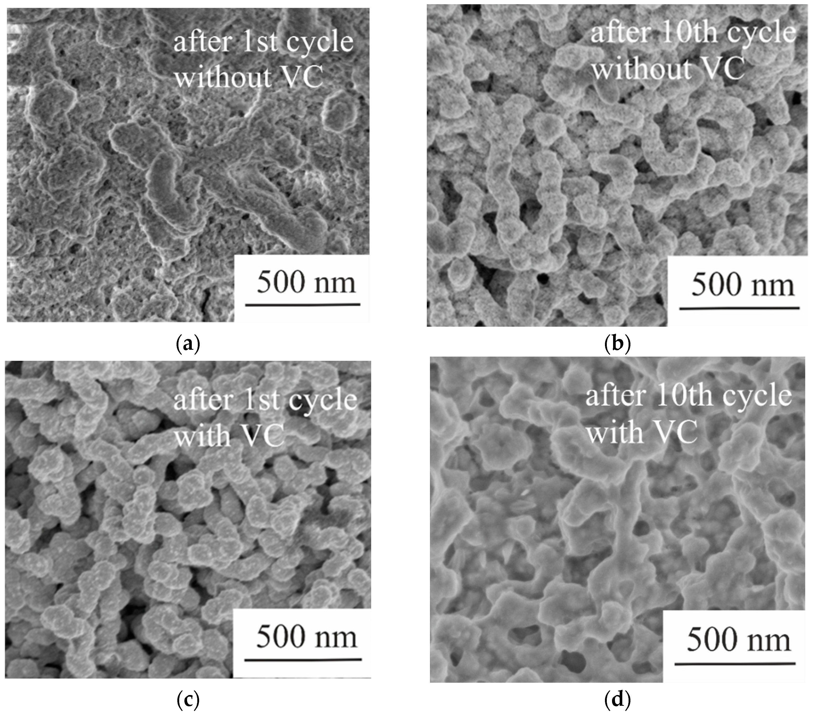
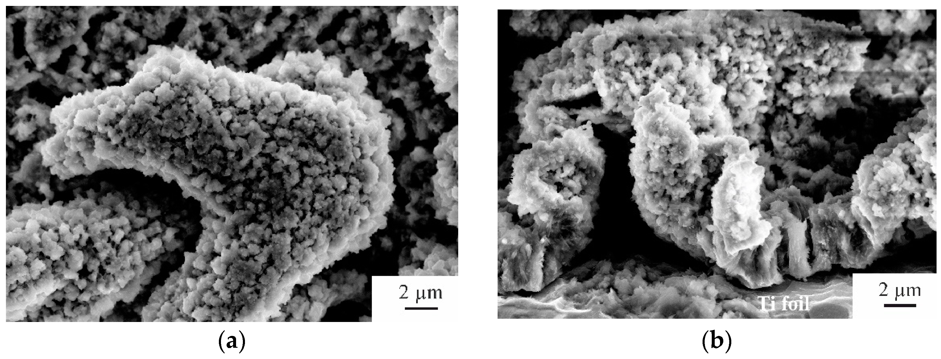
2.4. Morphological and Physical Studies of Samples after Sodium Insertion/Extraction

Figure 5 shows SEM images of the surface morphology of the samples after cycling in the without-VC and with-VC electrolyte solutions.
Figure 5 shows that the surface of the sample after the first cathodic polarization in the electrolyte solution without VC is covered with a thick film (Figure 5a), and after the tenth cycle this layer is not observed (Figure 5b). In contrast, the surface morphology of the sample after the first cycle of operation in the electrolyte solution with VC (Figure 5c) is similar to the morphology of the initial sample (Figure 1a), i.e., after the first cathodic polarization in the electrolyte solution with VC, this thick film on the surface of the Ge microrods is not observed. However, after the tenth cycle, a passive layer was formed on the surface of the Ge microrods (Figure 5d).

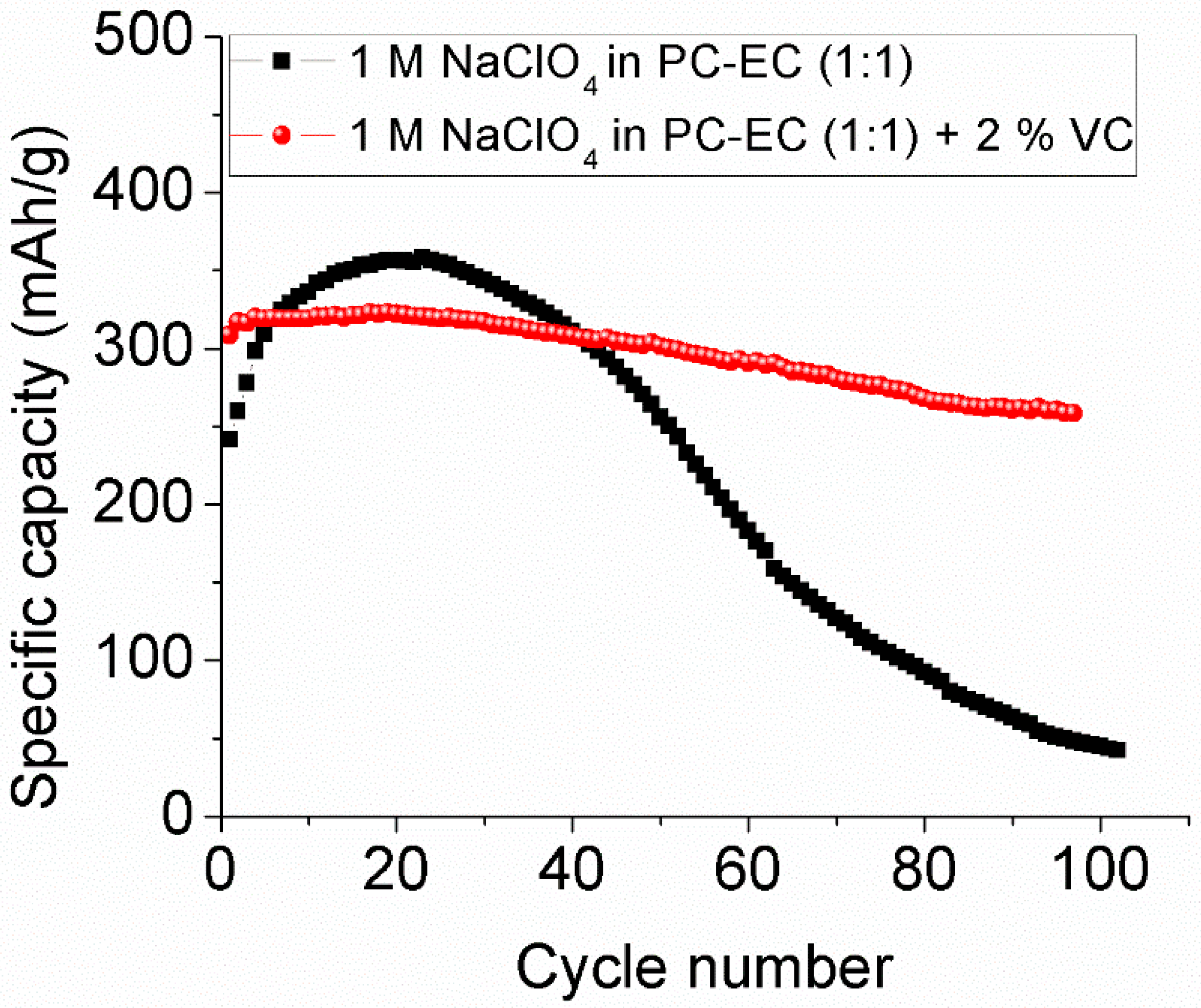
2.5. Long-Term Cycling of Samples

The cycling performance of the samples at 125 mA/g in the with-VC and without-VC electrolyte solutions is depicted in Figure 6.
During the cycling of Ge microrods in the electrolyte solution without VC, an increase in the discharge capacity was observed in the first cycles. After the twentieth charge/discharge cycle, the specific capacity of the Ge microrods in the electrolyte solution without VC began to gradually decrease from cycle to cycle and almost dropped to zero by the hundredth cycle. In contrast, after 100 cycles in the electrolyte solution with VC, a small decrease in capacity, from 300 mAh/g to 260 mAh/g, was recorded.
Figure 7 shows the SEM images of the surface morphology of the electrodes after long cycling (100 cycles) in the electrolyte solution with VC.
Figure 8 vividly demonstrates the effect of the VC additive on rate capability. The electrodes were cycled electrolytes with consequently increased current densities (50, 125, 250, 500, 1000, and 2000 mA/g), with five cycles at every current density.
As shown in Figure 8, at low currents, the discharge capacity in the electrolyte with VC was inferior (but insignificantly so) to that of electrolyte without VC. At higher currents, the electrolyte with VC displayed a notable advantage, i.e., much more stable cycling. Thus, at the thirtieth cycle, at current density 2 A/g, the discharge capacities in the VC-free and VC-containing electrolytes amounted to 118 mAh/g and 168 mAh/g, respectively. After returning to the initial low current density, the electrode in the electrolyte with VC retained its initial capacity, whereas the electrode in the electrolyte without VC showed a significant degradation rate.

3. Discussion

Comparing the obtained data, we concluded that the addition of VC in the electrolyte significantly affected the cycleability of the electrode, based on the Ge microrods. This effect can be explained by the fact that a thick passive film was formed on the surface of the Ge microrods during the first cycle (in the case of cycling in an electrolyte without VC), which was well illustrated by the obtained SEM images. This film was not stable and completely dissolved on the surface by the tenth cycle, thereby increasing the electrode capacity. The dissolution of this film during cycling was also confirmed by the results of electrochemical impedance spectroscopy. Specifically, the resistance of this passive film decreased by 11 times by the tenth cycle. In turn, the addition of VC in the electrolyte made it possible to form a more stable thin passive film on the surface of the Ge microrods; as a result, the electrode already demonstrated a high reversible capacitance during the first cycle. According to electrochemical impedance spectroscopy, the addition of VC reduced the resistance of the passive film by 12 times during the first cycle.
It should be noted that the thickness of this passive film increased at the tenth cycle, which was confirmed by the results of scanning electron microscopy and electrochemical impedance spectroscopy. Specifically, the resistance of the passive film increases by four times. However, that change did not affect the stability of the electrode, up to 100 cycles, while cycling the electrode in an electrolyte without VC led to its complete degradation.

4. Materials and Methods

4.1. Samples Preparation

Ge microrods were formed by electrochemical deposition from aqueous GeO2 solutions, using indium seeds as described in [20]. Titanium foil was used as the substrate and current collector. The titanium substrates were previously chemically cleaned. To form an array of indium seeds, vacuum–thermal evaporation was used.
Electrochemical deposition of Ge microrods was performed from electrolyte containing 0.05 M GeO2, 0.5 M K2SO4 and 0.5 M of C4H6O4. The solution’s pH was raised to 6.5 by adding NH4OH. Deposition was performed at −1.3V and at the solution temperature of 90 °C. The obtained samples were washed in deionized water and dried in an argon flow.

4.2. Material Characterization

The structure and surface morphology were characterized by scanning electron microscopy using a Helios NanoLab 650 Dual Beam microscope and transmission electron microscopy using Titan Themis 200, as described in [32].

4.3. Electrochemical Characterization

The electrochemical characterization consisted of cyclic voltammetry (CV), chronopotentiometry (galvanostatic cycling), and electrochemical impedance spectroscopy (EIS). All electrochemical experiments were carried out in three-electrode mode. The working electrodes were Ge-nanowires; the auxiliary and reference electrodes were made from sodium metal. The working electrodes, sized 1 cm2, were preliminarily vacuum-dried at 120 °C for 8 h. The electrolyte was used in the present study: 1M NaClO4 in the mixture propylene carbonate–ethylene carbonate (1:1), with an additive of 2% vinylene carbonate (VC), or VC-free. The electrolyte humidity (K. Fischer) was less than 15 ppm. All manipulations with the cells, including the assembling and electrolyte filling, were carried out in a glovebox with argon atmosphere (Spektroskopicheskie Sistemy, Russia). Multichannel potentiostat P-20X (Elins, Russia) was used for CV and EIS, computer-aided cycler AZVRIK-50-10V (Buster JSC, Russia), for galvanostatic cycling.

5. Conclusions

The addition of VC to the electrolytes allowed the formation of a more stable passive film on the surface of the Ge microrods, thereby significantly reducing the irreversible capacity during the first charge/discharge cycles and increasing the long-term cycling stability of the Ge microrods. The obtained results will benefit the further development of Ge microrods-based anodes that are formed by simple electrochemical deposition.

Author Contributions

E.A.L. shared the responsibility for the methodology and the writing of the original draft; I.M.G. shared the responsibility for the methodology, the investigation, and the writing of the original draft; Y.O.K. shared the responsibility for the investigation and the visualization; I.K.M. and R.L.V. also shared the responsibility for the investigation; T.L.K. shared the responsibility for the conceptualization and the writing of the original draft; A.M.S. shared the responsibility for the conceptualization and supervision; N.I.B.—investigation, supervision; S.A.G. also shared the responsibility for the conceptualization and the supervision. All authors have read and agreed to the published version of the manuscript.

Funding

The reported study was funded by the Russian Foundation for Basic Research (RFBR), project number 19-38-60058, and by the State assignment 2020–2022, number FSMR-2020-0018.

Institutional Review Board Statement

Not applicable.

Informed Consent Statement

Not applicable.

Data Availability Statement

Not applicable.

Conflicts of Interest

The authors declare no conflict of interest.

References

  1. Hwang, J.-Y.; Myung, S.-T.; Sun, Y.-K. Sodium-Ion Batteries: Present and Future. Chem. Soc. Rev. 2017, 46, 3529–3614. [Google Scholar] [CrossRef] [PubMed]
  2. Usiskin, R.; Lu, Y.; Popovic, J.; Law, M.; Balaya, P.; Hu, Y.-S.; Maier, J. Fundamentals, status and promise of sodium-based batteries. Nat. Rev. Mater. 2021, 6, 1020–1035. [Google Scholar] [CrossRef]
  3. Hu, Y.-S.; Lu, Y. Nobel prize for the Li-ion batteries and new opportunities and challenges in Na-ion batteries. ACS Energy Lett. 2019, 4, 2689–2690. [Google Scholar] [CrossRef]
  4. Yabuuchi, N.; Kubota, K.; Dahbi, M.; Komaba, S. Research development on sodium-ion batteries. Chem. Rev. 2014, 114, 11636–11682. [Google Scholar] [CrossRef] [PubMed]
  5. Kundu, D.; Talaie, E.; Duffort, V.; Nazar, L.F. The Emerging Chemistry of Sodium Ion Batteries for Electrochemical Energy Storage. Angew. Chem. Int. Ed. 2015, 54, 3431–3448. [Google Scholar] [CrossRef]
  6. Skundin, A.M.; Kulova, T.L.; Yaroslavtsev, A.B. Sodium-Ion Batteries (a Review). Russ. J. Electrochem. 2018, 54, 113–152. [Google Scholar] [CrossRef]
  7. Kalisvaart, W.P.; Olsen, B.C.; Luber, E.J.; Buriak, J.M. Sb–Si Alloys and Multilayers for Sodium-Ion Battery Anodes. ACS Appl. Energy Mater. 2019, 2, 2205–2213. [Google Scholar] [CrossRef]
  8. Farbod, B.; Cui, K.; Kalisvaart, W.P.; Kupsta, M.; Zahiri, B.; Kohandehghan, A.; Lotfabad, E.M.; Li, Z.; Luber, E.J.; Mitlin, D. Anodes for Sodium Ion Batteries Based on Tin–Germanium–Antimony Alloys. ACS Nano 2014, 8, 4415–4429. [Google Scholar] [CrossRef]
  9. Niu, L.; Guo, S.; Liang, W.; Song, L.; Song, B.; Zhang, Q.; Wu, L. In Situ Electrochemical Derivation of Sodium-Tin Alloy as Sodium-Ion Energy Storage Devices Anode with Overall Electrochemical Characteristics. Crystals 2022, 12, 575. [Google Scholar] [CrossRef]
  10. Zhang, L.; Hu, X.; Chen, C.; Guo, H.; Liu, X.; Xu, G.; Zhong, H.; Cheng, S.; Wu, P.; Meng, J.; et al. In operando mechanism analysis on nanocrystalline silicon anode material for reversible and ultrafast sodium storage. Adv. Mater. 2017, 29, 1604708. [Google Scholar] [CrossRef]
  11. Gibertini, E.; Liberale, F.; Dossi, C.; Binda, G.; Mattioli, B.; Bettinetti, R.; Maspero, A.; Fiore, M.; Ruffo, R.; Magagnin, L. Algae-derived hard carbon anodes for Na-ion batteries. J. Appl. Electrochem. 2021, 51, 1665–1673. [Google Scholar] [CrossRef]
  12. Simone, V.; Boulineau, A.; de Geyer, A.; Rouchon, D.; Simonin, L.; Martinet, S. Hard carbon derived from cellulose as anode for sodium ion batteries: Dependence of electrochemical properties on structure. J. Energy Chem. 2016, 25, 761–768. [Google Scholar] [CrossRef]
  13. Hu, Y.; Li, B.; Jiao, X.; Zhang, C.; Dai, X.; Song, J. Stable Cycling of Phosphorus Anode for Sodium-Ion Batteries through Chemical Bonding with Sulfurized Polyacrylonitrile. Adv. Funct. Mater. 2018, 28, 1801010. [Google Scholar] [CrossRef]
  14. Liu, Y.; Liu, Q.; Jian, C.; Cui, D.; Chen, M.; Li, Z.; Li, T.; Nilges, T.; He, K.; Jia, Z.; et al. Red-phosphorus-impregnated carbon nanofibers for sodium-ion batteries and liquefaction of red phosphorus. Nat. Commun. 2020, 11, 2520. [Google Scholar] [CrossRef] [PubMed]
  15. Liu, Y.; Zhang, A.; Shen, C.; Liu, Q.; Cao, X.; Ma, Y.; Chen, L.; Lau, C.; Chen, T.C.; Wei, F.; et al. Red phosphorus nanodots on reduced graphene oxide as a flexible and ultra-fast anode for sodium-ion batteries. ACS Nano 2017, 11, 5530–5537. [Google Scholar] [CrossRef] [PubMed]
  16. Yaru, W.; Wang, P.; Zhao, D.; Hu, B.; Du, Y.; Xu, H.; Chang, K. Thermodynamic description of the Ge–Na and Ge–K systems using the CALPHAD approach supported by first-principles calculations. Calphad 2012, 37, 72–76. [Google Scholar] [CrossRef]
  17. Legrain, F.; Malyi, O.; Manzhos, S. Comparative computational study of the diffusion of Li, Na, and Mg in silicon including the effect of vibrations. Solid State Ion. 2013, 253, 157–163. [Google Scholar] [CrossRef]
  18. Kohandehghan, A.; Cui, K.; Kupsta, M.; Ding, J.; Lotfabad, E.M.; Kalisvaart, W.P.; Mitlin, D. Activation with Li enables facile sodium storage in germanium. Nano Lett. 2014, 14, 5873–5882. [Google Scholar] [CrossRef]
  19. Gavrilin, I.M.; Smolyaninov, V.A.; Dronov, A.A.; Gavrilov, S.A.; Trifonov, A.Y.; Kulova, T.L.; Kuz’mina, A.A.; Skundin, A.M. Electrochemical insertion of sodium into nanostructured materials based on germanium. Mendeleev Commun. 2018, 28, 659–660. [Google Scholar] [CrossRef]
  20. Gavrilin, I.M.; Kudryashova, Y.O.; Kulova, T.L.; Skundin, A.M.; Gavrilov, S.A. The effect of growth temperature on the process of insertion/extraction of sodium into germanium nanowires formed by electrodeposition using indium nanoparticles. Mater. Lett. 2021, 287, 129303. [Google Scholar] [CrossRef]
  21. Iermakov, I.; Dugas, R.; Palacín, M.R.; Ponrouch, A. On the Comparative Stability of Li and Na Metal Anode Interfaces in Conventional Alkyl Carbonate Electrolytes. J. Electrochem. Soc. 2015, 162, A7060. [Google Scholar] [CrossRef]
  22. Gao, L.; Chen, J.; Chen, Q.; Kong, X. The chemical evolution of solid electrolyte interface in sodium metal batteries. Sci. Adv. 2022, 8, 1–7. [Google Scholar] [CrossRef]
  23. Mogensen, R.; Brandell, D.; Younesi, R. Solubility of the Solid Electrolyte Interphase (SEI) in Sodium Ion Batteries. ACS Energy Lett. 2016, 1, 1173–1178. [Google Scholar] [CrossRef]
  24. Li, K.; Zhang, J.; Lin, D. Evolution of the electrochemical interface in sodium ion batteries with ether electrolytes. Nat. Commun. 2019, 10, 725. [Google Scholar] [CrossRef]
  25. Ponrouch, A.; Marchante, E.; Courty, M.; Tarascon, J.-M.; Palacín, M.R. In search of an optimized electrolyte for Na-ion batteries. Energy Environ. Sci. 2012, 5, 8572. [Google Scholar] [CrossRef]
  26. Ushirogata, K.; Sodeyama, K.; Tateyama, Y.; Okuno, Y.; Tateyama, Y. Additive Effect on Reductive Decomposition and Binding of Carbonate-Based Solvent toward Solid Electrolyte Interphase Formation in Lithium-Ion Battery. J. Am. Chem. Soc. 2013, 135, 11967–11974. [Google Scholar] [CrossRef]
  27. Jaumann, T.; Balach, J.; Langklotz, U.; Sauchuk, V.; Fritsch, M.; Michaelis, A.; Teltevskij, V.; Mikhailova, D.; Oswald, S.; Klose, M. Lifetime vs. rate capability: Understanding the role of FEC and VC in high-energy Li-ion batteries with nano-silicon anodes. Energy Storage Mater. 2017, 6, 26–35. [Google Scholar] [CrossRef]
  28. Nie, M.; Demeaux, J.; Young, B.T.; Heskett, D.R.; Chen, Y.; Bose, A.; Woicik, J.C.; Lucht, B.L. Effect of Vinylene Carbonate and Fluoroethylene Carbonate on SEI Formation on Graphitic Anodes in Li-Ion Batteries. J. Electrochem. Soc. 2015, 162, A7008–A7014. [Google Scholar] [CrossRef]
  29. Ahn, S.; Fukushima, M.; Nara, H.; Momma, T.; Sugimoto, W.; Osaka, T. Effect of fluoroethylene carbonate and vinylene carbonate additives on full-cell optimization of Li-ion capacitors. Electrochem. Commun. 2021, 122, 106905. [Google Scholar] [CrossRef]
  30. Michan, A.L.; Parimalam, B.S.; Leskes, M.; Kerber, R.N.; Yoon, T.; Grey, C.P.; Lucht, B.L. Fluoroethylene Carbonate and Vinylene Carbonate Reduction: Understanding Lithium-Ion Battery Electrolyte Additives and Solid Electrolyte Interphase Formation. Chem. Mater. 2016, 28, 8149–8159. [Google Scholar] [CrossRef] [Green Version]
  31. Kitz, P.G.; Lacey, M.J.; Novák, P.; Berg, E.J. Operando investigation of the solid electrolyte interphase mechanical and transport properties formed from vinylene carbonate and fluoroethylene carbonate. J. Power Sources 2020, 477, 228567. [Google Scholar] [CrossRef]
  32. Gavrilin, I.M.; Kudryashova, Y.O.; Kuz’mina, A.A.; Kulova, T.L.; Skundin, A.M.; Emets, V.V.; Volkov, R.L.; Dronov, A.A.; Borgardt, N.I.; Gavrilov, S.A. High-rate and low-temperature performance of germanium nanowires anode for lithium-ion batteries. J. Electroanal. Chem. 2021, 888, 115209. [Google Scholar] [CrossRef]
Figure 1. (a) SEM image of the Ge microrods with a core–shell structure; (b) HAADF-STEM image of a cross section of the Ge microrods with a core–shell structure; (c) HRTEM image of a fragment of a cross section of a Ge microrod.
Batteries 08 00109 g001
Figure 2. CVs for Ge microrods in electrolyte without VC (a) and with VC (b) at the scan rate of 0.1 mV/s. Cycles numbers are shown in the plots.
Batteries 08 00109 g002
Figure 3. Nyquist plots of Ge microrods in the without-VC (a) and the with-VC (b) electrolyte solutions.
Batteries 08 00109 g003
Figure 4. An equivalent circuit of Ge microrods. Reproduced with permission from [32]. Elsevier, 2021.
Batteries 08 00109 g004
Figure 5. SEM images of the surface morphology of the samples after cycling in without-VC (a,b) and with-VC (c,d) electrolyte solution.
Batteries 08 00109 g005
Figure 6. Change in the discharge capacity of Ge in without-VC and with-VC electrolyte solutions at 125 mA/g.
Batteries 08 00109 g006
Figure 7. SEM images of the surface morphology (a) and cross-section (b) of the samples after long cycling in the electrolyte solution with VC.
Batteries 08 00109 g007
Figure 8. Specific capacity vs. cycle number of Ge microrods upon cycling in different electrolytes at various current densities.
Batteries 08 00109 g008
Table 1. The calculated parameters of the equivalent circuit.
Ge MicrorodsRs, OhmRsei, Ohm/cm2Csei, F/cm2Rct, Ohm/cm2Cdl,
F/cm2
W,
Ohm/s0.5
1M NaClO4 in PC-EC after 1 cycle1312.554.47 × 10−7295.54.3 × 10−5133
1M NaClO4 in PC-EC after 10 cycles91.24.25 × 10−71751.4 × 10−5215
1M NaClO4 in PC-EC + 2%VC after 1 cycle131.054.7 × 10−7219.76 × 10−6342
1M NaClO4 in PC-EC + 2%VC after 10 cycles1541.0 × 10−72705.5 × 10−6202
Publisher’s Note: MDPI stays neutral with regard to jurisdictional claims in published maps and institutional affiliations.

