
Binder-Free Ge-Co-P Anode Material for Lithium-Ion and Sodium-Ion Batteries
by

Tatiana L. Kulova
1,*,
Alexander M. Skundin
1,
Il’ya M. Gavrilin
1,2,
Yulia O. Kudryashova
1,
Irina K. Martynova
2 and
Svetlana A. Novikova
3
1
Frumkin Institute of Physical Chemistry and Electrochemistry, Russian Academy of Sciences, 31-4 Leninskii pr., 119071 Moscow, Russia
2
Institute of Advanced Materials and Technologies, National Research University of Electronic Technology (MIET), Bld. 1, Shokin Square, Zelenograd, 124498 Moscow, Russia
3
Kurnakov Institute of General and Inorganic Chemistry, Russian Academy of Sciences, 31 Leninskii pr., 119991 Moscow, Russia
*
Author to whom correspondence should be addressed.
Batteries 2022, 8(8), 98; https://doi.org/10.3390/batteries8080098
Submission received: 26 July 2022
/
Revised: 15 August 2022
/
Accepted: 17 August 2022
/
Published: 19 August 2022
(This article belongs to the Section Battery Modelling, Simulation, Management and Application)
Abstract
:Nanostructure composites Ge-Co-P with brutto-composition CoGe2P0.1, or CoGe2@GeP were manufactured via electrolysis of aqueous electrolyte. Such composites are able to reversible insertion of lithium and sodium with specific capacities up to 855 and 425 mAh/g, respectively. The main advantage of the composites consists in their excellent cycleability.
1. Introduction
Sodium-ion batteries are considered now as the next generation after lithium-ion ones. In general, important performance characteristics of sodium-ion batteries, such as energy density and cycleability are inferior to those of lithium-ion counterparts. Therefore, the considerable efforts are aimed now to development of new electrode materials with higher specific capacity and rate capability, as well as low capacity fading upon cycling.
Germanium attracts much attention as promising anode material for both lithium-ion and sodium-ion batteries due to its high theoretical specific capacity. In principle, germanium is able to insert lithium and sodium up to Li22Ge5, and Na3Ge [1], which corresponds to specific capacities of 1624 and 1107 mAh/g, respectively. The important advantage of germanium is rather high conductivity and lithium diffusivity, which provides high rate capability. At the same time, similar to other materials with high insertion capacity, germanium suffers a notable volume expansion upon lithium and sodium insertion. This phenomenon results in material fracture up to pulverization and loss of electrical contacts, which limits the cycleability of Ge-based anodes. Various strategies were supposed for the improvement of the cycling stability of such anodes, including the replacement of germanium alloys for pure germanium. In particular, Ge-Co alloys were mentioned [2,3,4]. However, the results reported in [2,3,4] could not be considered as unambiguous. Indeed, [2] describes composites of three intermetallic compounds, CoGe, Co5Ge7, and CoGe2 with carbon, and declares a specific capacity of CoGe2@C towards lithium insertion as low as 230 mAh/g, provided correctly accounted for the density of CoGe2@C. Even with an allowance made for the fact that cobalt is an inactive component (i.e., the component does not contribute to lithium insertion), this value is far from theoretical. At the same time, the authors of [3] describe core–shell structures of Co5Ge3@Co anchored on the sheets of reduced graphene oxide. They believe Co is not an inactive component, because redox-transformation Co2+/Co3+ contributes some extra capacity. Finally, some unrealistic performances are reported in [4]. Here, Co-Ge three-dimensional nanowire arrays consisting of core–shell structures (Co cores and amorphous Ge shells) at copper supports were studied. The authors do not present the exact composition of the structures, but specific capacity by lithium insertion, namely 1535 mAh/g after 100 cycles at C/5, and capacity by sodium insertion, namely ca. 400 mAh/g after 100 cycles at 100 mA/g seem overestimated.
Phosphorus is well known to be another material with a high capacity for sodium insertion. Moreover, various germanium–phosphorus composites, as well as germanium phosphides, also demonstrate good insertion capability for both lithium and sodium [5,6,7,8,9,10,11,12,13,14,15,16,17,18,19,20,21]. Three various germanium phosphides were studied, specifically, GeP [5,6,13,18,19,20,21], GeP3 [14,15,16], and GeP5 [8,9,10,11,12]. Again, despite a fairly large number of studies on these systems, their results cannot be considered unambiguous. For instance, a drastic difference in the electrochemical behavior of GeP and an intimate mixture of elemental germanium and phosphorus were reported in [5]. Meanwhile, many authors (see, e.g., [6,10,11,16,21]) suggest that at the first cathodic polarization germanium phosphide transforms into Li3P + LiyGe (or Na3P + NaGe), and then reversible lithium or sodium insertion into phosphorus and germanium has its place.
Herein, we present data on binder-free electrodes based on a three-component system Ge-Co-P concerning its behavior as negative electrodes (anodes) in lithium-ion and sodium-ion batteries.
The binder-free electrode possesses certain advantages, since the process of their manufacture is simplified, and they provide increases in the specific capacity of the electrode and metal-ion batteries in general [22]. In addition, due to the expansion of the areas of application of lithium-ion batteries, there is a need to reduce inactive materials in the composition of the electrode. This can be achieved by using electroactive binders [23], conductive substrates [24,25], or by various methods for the manufacture of binder-free electrodes, e.g., electrophoretic deposition [26,27], electrospinning [28], vacuum filtration [29], physical vapor deposition [30], electrodeposition [31,32]. Binder-free electrodes show better electrochemical performances than those made by casting technology, since nano-sized materials are more uniformly distributed on the substrates, which can effectively prevent nanoparticle agglomeration and reduce volume expansion during multiple cycling.
2. Results
2.1. Morphological and Physical Studies
Figure 1a demonstrates the results of X-ray fluorescence analysis. Cobalt and germanium are seen very clearly on the spectrum. In addition to some background elements, which are shown in grey, titanium and indium are also seen rather certainly. The wave from phosphorus happened to be very weak.
The results of XRD are shown in Figure 1b. Against the background of huge peaks from titanium, one can see a low intensity, poorly resolved reflections in the 2Ɵ ranges of 33 degrees and 45-46 degrees, which can be attributed to CoGe2 orthorhombic modification (Card 07-0162). The low-intensive peak at about 27 degrees could be related to GeP tetragonal modification (21-0346). Therefore, XRD analysis does not allow some unambiguous conclusion on the phase composition of Ge-Co-P nanostructures.
The results of EDX analysis (Figure 1c) show that the relation Ge:Co:P is close to 10:19:1, which coincides by and large with the results of XRD The composition of Ge-Co-P nanostructures could be expressed with brutto-formula CoGe2P0.1 or CoGe2@GeP. It deserves mention that CoGe2 is the most stable germanium-rich phase in the binary system Co-Ge [33].
The morphology of Ge-Co-P nanostructures can be seen in Figure 2. One can see that this morphology drastically differs from wire-like morphology of nanostructures of pure germanium [34] or rod-like morphology of germanium phosphide [21]. Ge-Co-P nanostructures consist of rounded cube-like particles sized 0.5 to 1.5 µm. These particles have a secondary structure and consist of much smaller primary particles. Figure 2c,d show cross section image of the same sample, confirming a binder absence.
2.2. Electrochemical Studies of Lithium Insertion/Extraction
Figure 3a shows cyclic voltammograms (CVs) of the sample under study. The cathode branches of CVs display two pronounced peaks, and on the anode branches, two corresponding peaks are seen as well. At the least scan rate (0.05 mV/s) the cathode peaks are registered at potentials 0.48 and 0.10 V, and anode ones at potentials 0.44 and 1.08 V. Close CVs were reported in [5,6] for reversible lithium insertion into GeP. Therein cathodic peaks are ascribed to the formation of Li3P and LiyGe. The increase in scan rate results in the displacement of cathode peaks in the negative, and anode peaks in the positive direction, which reflects certain slowness of the electrode processes. It is worth noting the excellent reproducibility of CV: Figure 3a displays three curves for successive cycles, and all curves coincide. Figure 3b shows CVs of the lithium insertion/extraction into/from Ge-Co nanostructure.
The comparison of CVs in Figure 3a,b allows the revealing role of the phosphorous component in CoGe2P0.1. Despite the relatively low phosphorus content in the composite, its presence has a significant effect on the CV shape.
Figure 4 demonstrates galvanostatic charge (cathode) and discharge (anode) curves, taken with current densities of 25, 50, and 100 mA/g. Here, three curves at each current density are shown too.
One can clearly behold two clear (although inclined) plateaus at anode curves at potentials ca. 0.5 and 1.1 V, which is in good agreement with peaks at CVs. Noteworthy is the rather weak dependence of discharge capacity on C-rate: discharge capacity at current densities 25, 50, and 100 mA/g amounted to 855, 825, and 780 mAh/g. Theoretic specific capacity of CoGe2 provided the supposition that germanium is active, and cobalt is inactive components amounts to 1100 mAh/g. Thus, the experimental specific capacity reaches 77% from theory. Intriguingly, the shape of galvanostatic curves in Figure 4 notably differs from the shapes of galvanostatic curves for plain Ge [34] and GeP [21], despite the similarity of corresponding CVs.
2.3. Electrochemical Studies of Sodium Insertion/Extraction
CVs for processes of sodium insertion/extraction into/from Ge-Co-P nanostructures are shown in Figure 5a. Again, this figure displays three consecutive curves at the potential scan rate of 0.05 mV/s, and three curves at the scan rate of 0.1 mV/s. First and foremost, one can see a notable difference in CVs in lithium and sodium systems: all currents in Figure 6 are several times as low as that in Figure 4, which testifies to the slowness of sodium insertion in comparison to that of lithium. The anode and especially cathode peaks in Figure 6 are less pronounced than in Figure 3. However, more or less legible cathodic peaks at potentials 0.47 and 0.10 V, as well as corresponding anodic peaks at potentials 1.27 and 0.54 V can be seen. It deserves mention that the CVs in Figure 5a differ but insignificantly from CVs in [19]. Figure 5b shows galvanostatic charge (cathode) and discharge (anode) curves for sodium insertion/extraction, taken with current densities of 25, 50, and 100 mA/g. Again, several curves at each current density are shown. It is hardly possible to distinguish clear plateaus at the cathode curve. Some plateaus at anode curves could be seen at potentials ca. 0.5 and 1.3 V. The discharge capacity in this case at current densities of 25, 50, and 100 mA/g amounted to 425, 375, and 337 mAh/g.
2.4. Impedance Measurements of CoGe2P0.1
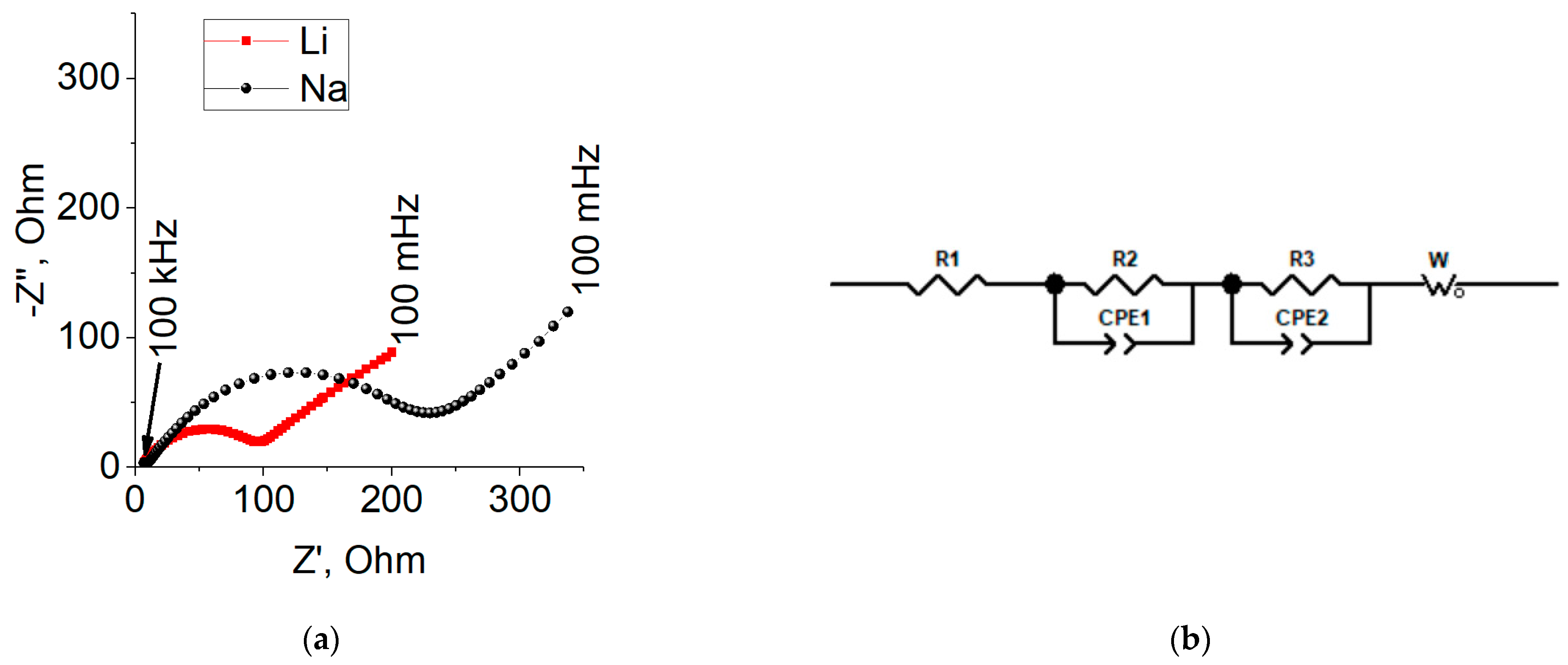
The typical Nyquist plots of CoGe2P0.1 at lithium and sodium insertion are depicted in Figure 6a. Both plots contain semicircles in the high- and middle-frequency range and a straight line in the low-frequency range. On the whole, the impedance of CoGe2P0.1 (semicircle diameter) at sodium insertion exceeds that upon lithium insertion. The equivalent circuit simulating the impedance is shown in Figure 6b.
Here, R1 is an electrolyte resistance, R2 is a resistance of the passive film, CPE1 is a constant phase element, which characterizes the capacitance of the passive film (Cf), R3 is charge transfer resistance, CPE2 is a constant phase element, relating to electrical double layer capacity (Cdl), W is Warburg impedance. Based on the measured parameters of the equivalent circuit, the values of R1, R2, Cf, R3, Cdl, and Wo1 were calculated, which are presented in Table 1. As can be seen, the charge transfer resistance (R3) with sodium insertion is about twice that with lithium insertion, which coincides with the data in Figure 6a. The capacitance of the passive film (Cf) and the capacitance of the double layer (Cdl) in the case of sodium insertion are an order of magnitude higher than the corresponding values for lithium insertion. This fact is rather surprising. The Warburg constant (W) at both lithium and sodium are the same in order.
The knowledge of the W value allows for calculating diffusions coefficients of lithium and sodium. With a due account for the fact that the activity coefficient of lithium and sodium inserted are unknown, the calculations were carried out using Equation borrowed from [35]:
where F is the Faraday number, S is the true surface area, W is the Warburg constant, dE/dc is the slope of the potential concentration dependence. The last value was calculated from experimental E-c dependences (Figure 7), and it happened to be about 4.76 and 8.43 V·cm3/mole for the insertion of lithium and sodium, respectively.
The effective diffusion coefficient of lithium and sodium upon insertion into CoGe2P0.1 was 7 × 10⁻¹³ and 4 × 10⁻¹³ cm2/s. At lithium and sodium extraction, the effective diffusion coefficient turned out to be practically the same and amounted to about 2 × 10⁻¹² cm2/s. Thus, the lower specific capacity upon sodium insertion may be due to diffusion hindrances.
Thus, the mechanism of reversible insertion of lithium and sodium into CoGe2P0.1 could be expressed by the following equations.
CoGe2P0.1 + 8.7 Li ↔ Co + 2 Li4.2Ge + 0.1 Li3P
CoGe2P0.1 + 4.3 Na ↔ Co + 2 Na2Ge + 0.1 Na3P
As shown in the foregoing, the theoretical specific capacity of CoGe2P0.1 for lithium insertion amounted to 1131 mAh/g, whereas the practical value was 855 mAh/g or 76% from the theory. The theoretical value of the specific capacity of CoGe2P0.1 for sodium insertion is 560 mAh/g. The practical value amounted to 425 mAh/g or 76% of the theory seems to be low.
2.5. Long-Term Cycling
Galvanostatic long-term tests were carried out at a current density of 400 mA/g in the course of lithium insertion/extraction and in the course of sodium insertion/extraction. These values of current density are four times the maximal current densities noted in Figure 4 and Figure 5b. The need to increase the current density was dictated by the too-long duration of multiple cycling at low current densities. Figure 8 shows the performances of CoGe2P0.1 upon long-term cycling. Figure 8a,b demonstrate charge/discharge curves for experiments with lithium and sodium, respectively, cyclic performances are shown in Figure 8c. As can be seen, there is a certain difference in cycling behavior upon insertion/extraction of lithium and sodium. In the former case, one can note some increase in capacity during the initial fifteen cycles. Only after the 17th cycle usual capacity fading occurs. In the latter case, the capacity increases but insignificantly for the initial 35 cycles whereas during the following cycling the capacity remains intact. It is worth noting that in our earlier studies of lithium and sodium reversible insertion into germanium nanowires we observed the same effect. Then, we considered it as the manifestation of germanium pulverization upon insertion of large amounts of alkali metals [34,36,37].
As is easy to verify from Figure 8a,b, the multiple cycling does not result in a change in the shape of the charge and discharge curves. This means that, even with long-term cycling, there is no serious structural rearrangement of the composite CoGe2P0.1.
The cycling Coulomb efficiency at lithium and sodium insertion into CoGe2P0.1 was notably less than unit only in the initial cycles. Thus, when lithium is inserted, the Coulomb efficiency in the first cycle was 0.95 and reached 0.98 by the tenth cycle. When sodium is inserted, the Coulomb efficiency was 0.74 and 0.97 in the first and tenth cycles, respectively. The rather high values of the Coulomb efficiency confirm the expediency of using CoGe2P0.1 as anode material in lithium-ion and sodium-ion batteries.
As can be inferred from Figure 4, Figure 5b and Figure 8a,b, an increase in current density at cycling results in a decrease in discharge capacity. The dependence of the specific capacity (Q) on current density (i) is shown in Figure 9. This dependence is presented in bi-logarithmic coordinates in the wake of the well-known Peukert equation
3. Discussion
The present study of the Ge-Co-P system was carried out to fill a gap between studies of Ge-P and Ge-Co systems as anode materials for lithium-ion and sodium-ion batteries. In addition, it should be noted that the results reported for Ge-P and Ge-Co systems are ambiguous. Nanostructured Ge-Co-P samples were manufactured via cathodic deposition from an aqueous electrolyte, which is a rather rare technic. Precise phase compositions of the samples remain unknown, but their elemental composition was determined based on the results of X-ray fluorescence analysis, EDX, and XRD. The sample under discussion has brutto-composition as CoGe2P0.1. Despite quite the low content of phosphorus its effect on electrochemical behavior happened to be notable.
Composite CoGe2P0.1 is able to reversibly insert both lithium and sodium and can be used in negative electrodes of lithium-ion and sodium-ion batteries. The main advantage of this material is its good cycleability. Another advantage consists of the weak dependence of capacity of CoGe2P0.1-based electrodes on C-rate.
It is of deep interest to consider an increase in specific capacity at the initial period of cycling. This phenomenon is revealed upon lithium but not sodium insertion. Moreover, the higher the current density, the clearer this phenomenon reveals. This feature calls for further investigation.
Peukert equation is known to be created for the description of performances of lead-acid batteries. Its applicability to analyzing the behavior of other batteries is not obvious; therefore, the results of the present work are of deep interest.
To illustrate the performance of CoGe2P0.1 as anode material of lithium-ion battery, a laboratory pouch cell was assembled and tested. Commercial layered oxide LiNi0.8Co0.15Al0.05O2 (Gelon LIB Co., Ltd., LinYi City, Shandong, China) was used as a cathode. The performances of this material are described in [38]. The features of pouch cells are described elsewhere [39]. The rated capacity of the pouch cell amounted to 2.5 mAh. The relation of the weight of the positive and negative electrodes was 4:1.
Figure 10 shows the charge–discharge curves of the pouch cell. The first two cycles (formatting cycles) were carried out at C/8, whereas the following cycling was carried out at C/4. One can see that the discharge capacity at the first and second cycles practically coincides. The increase in discharge current results in some capacity diminishing, which weakens upon cycling. The discharge voltage of the pouch cell amounted to 3.2 V, which is comparable with that of batteries “lithium iron phosphate—graphite”.
4. Materials and Methods
4.1. Samples Preparation
The samples under study were made from 50 μm thickness titanium foil (VT 1-0). The preliminary treatment of the samples included the following steps: (i) cleaning in a mixture of H2O-H2O2-NH4OH (4:1:1) at a temperature of 80 °C for 15 min, (ii) rinsing in hot deionized water, (iii) drying in an argon flow, (iv) surface activation in a mixture of H2O-HNO3-HF (6:2:1), (v) second rinsing in hot deionized water, (vi) final drying in an argon flow. Then, an array of spherical indium nanoparticles was deposited onto this surface by vacuum thermal evaporation at a residual pressure of 10−5 torr. These In nanoparticles subsequently played role of seeds (crystallization centers) for the growth of Ge-Co-P nanostructures. Indium was evaporated from molybdenum evaporator and placed at 40 cm from the sample. After In particles deposition the samples were annealed in vacuum at 150 °C for 15 min. Ge-Co-P nanostructures were cathodically deposited onto these samples in potentiostatic mode in a three-electrode cell. Pt plate was used as anode, Ag/AgCl as the reference electrode. The electrolyte for Ge-Co-P nanostructures deposition was prepared by mixing 1 part of solution A and 30 parts of solution B. Solution A contained 0.01 M CoSO4 (cobalt sulfate), 0.5 M Na(PH2O2) (sodium hypophosphite) и 0.1 M CH3COONa (sodium acetate). Solution B contained 0.1 M GeO2 (Germania), 0.1 M C4H6O4 (succinic acid), and 0.5 M K2SO4 (potassium sulfate). The deposition was carried out at potential −1.1 V for 10 min. with using of potentiostat/galvanostat Autolab PGSTAT302N (Metrohm, Barendrecht, The Netherlands). The weight of the obtained nanostructures was about 0.6 mg/cm2.
For the sake of comparison, samples of Ge-Co nanostructures were made by the same procedure using the electrolyte of the same composition save sodium hypophosphite.
4.2. Samples Physical Characterization of Ge-Co-P Nanostructures
X-ray fluorescence analysis was carried out using an X-ray diffractometer “Radian DR-02” with copper tube at accelerating voltage of 30 kV. XRD analysis was carried out using Rigaku D/MAX 2200 diffractometer with CuKα radiation. SEM images were obtained at electron microscope MAIA3 Tescan.
4.3. Electrochemical Characterization
4.3.1. Electrochemical Cells
All electrochemical cells were made from polytetrafluorethylene. They contained three electrodes, namely, a working electrode (Ge-Co-P nanostructures) sized by 1 cm2, counter electrode, and reference one. Both latter electrodes were made of metal lithium or sodium rolled onto the supporting nickel grid. The electrodes were separated by a separator made of nonwoven polypropylene (UFIM, Moscow Russia). The cells were hermetically sealed, and they were assembled and filled with an electrolyte in a glove box with dry argon (Spektroskopicheskie Sistemy, Russia). The water and oxygen content in the box is not exceed 1 ppm. Just before cell assembling the working electrodes were vacuum dried at 120 °C for 8 h. An amount of 1 M LiClO4 in a mixture propylene carbonate—dimethoxyethane (7:3), and M NaClO4 in a mixture propylene carbonate—ethylene carbonate (1:1) were used as electrolytes. The moisture content in both electrolytes measured by K. Fischer coulometric titration (917 Coulometer, Metrohm, Herisau, Switzerland) did not exceed 15 ppm.
4.3.2. Electrochemical Measurements
The measurements of specific capacity of Ge-Co-P nanostructures were made in galvanostatic (charge–discharge curves) and potentiodynamic (cycling voltammograms) modes. AZRIVK-50-10V cycler (JSC “Buster”, Saint-Petersburg, Russia) was used for galvanostatic measurements and potentiostat (ELINS STC JSC, Moscow Region, Russia) for cyclic voltammetry. Current densities at galvanostatic experiments varied from 25 to 400 mA/g, and scan rates at cyclic voltammetry were 0.05, 0.1, and 0.2 mV/s. The cycling potential limits were 0.01–3.0 V. The cycling voltage limits for pouch cells were 0.5–4.0 V.
Impedance measurements were carried out according to the three-electrode circuit using the same potentiostat (ELINS STC JSC, Russia) at a potential of 200 mV with disturbance amplitude of 10 mV and frequency range from 105 to 10−1 Hz. ZView software was used for analysis of impedance spectra.
5. Conclusions
The development of new electrode materials with higher specific capacity and rate capability, as well as low capacity fading upon cycling seems to be an urgent task for the improvement of lithium-ion and sodium-ion batteries. Nanostructure composites Ge-Co-P with brutto-composition CoGe2P0.1, or CoGe2@GeP were manufactured via electrolysis of aqueous electrolyte. Despite quite low content of phosphorus, the electrochemical behavior of the composites is different from that of CoGe2 and germanium phosphides. The composites are able to reverse the insertion of lithium and sodium with a specific capacity of up to 855 and 425 mAh/g, respectively, and could be considered a promising material for lithium-ion and especially, sodium-ion batteries.
Author Contributions
T.L.K.—conceptualization, writing of original draft, methodology; A.M.S.—conceptualization, supervision; I.M.G.—methodology, investigation; Y.O.K.—investigation, visualization; I.K.M.—investigation; S.A.N.—investigation. All authors have read and agreed to the published version of the manuscript.
Funding
This research was funded by Russian Science Foundation, grant number 21-13-00160.
Institutional Review Board Statement
Not applicable.
Informed Consent Statement
Not applicable.
Data Availability Statement
Not applicable.
Conflicts of Interest
The authors declare no conflict of interest.
References
- Wu, S.; Han, C.; Iocozzia, J.; Lu, M.; Ge, R.; Xu, R.; Lin, Z. Germanium-Based Nanomaterials for Rechargeable Batteries. Angew. Chem. Int. Ed. 2016, 55, 7898–7923. [Google Scholar] [CrossRef] [PubMed]
- Kim, D.-H.; Park, C.M. Co–Ge compounds and their electrochemical performance as high-performance Li-ion battery anodes. Mater. Today Energy 2020, 18, 100530. [Google Scholar] [CrossRef]
- Jing, Y.-Q.; Qu, J.; Jia, X.-Q.; Zhai, X.-Z.; Chang, W.; Zeng, M.-J.; Li, X.; Yu, Z.-Z. Constructing tunable core-shell Co5Ge3@Co nanoparticles on reduced graphene oxide by an interfacial bonding promoted Kirkendall effect for high lithium storage performances. Chem. Eng. J. 2021, 408, 127266. [Google Scholar] [CrossRef]
- Zhao, W.; Chen, J.; Lei, Y.; Du, N.; Yang, D. A novel three-dimensional architecture of Co–Ge nanowires towards high-rate lithium and sodium storage. J. Alloys Compd. 2020, 815, 152281. [Google Scholar] [CrossRef]
- Li, W.; Li, X.; Yu, J.; Liao, J.; Zhao, B.; Huang, L.; Abdelhafiz, A.; Zhang, H.; Wang, J.-H.; Guo, Z.; et al. A self-healing layered GeP anode for high-performance Li-ion batteries enabled by low formation energy. Nano Energy 2019, 61, 594–603. [Google Scholar] [CrossRef]
- Shen, H.; Huang, Y.; Chang, Y.; Hao, R.; Ma, Z.; Wu, K.; Du, P.; Guo, B.; Lyu, Y.; Wang, P.; et al. Narrowing Working Voltage Window to Improve Layered GeP Anode Cycling Performance for Lithium-Ion Batteries. ACS Appl. Mater. Interfaces 2020, 12, 17466–17473. [Google Scholar] [CrossRef]
- Yan, Y.; Ruan, J.; Xu, H.; Xu, Y.; Pang, Y.; Yang, J.; Zheng, S. Fast and Stable Batteries with High Capacity Enabled by Germanium−Phosphorus Binary Nanoparticles Embedded in a Porous Carbon Matrix via Metallothermic Reduction. ACS Appl. Mater. Interfaces 2020, 12, 21579–21585. [Google Scholar] [CrossRef]
- He, J.; Wei, Y.; Hu, L.; Li, H.; Zhai, T. Aqueous Binder Enhanced High-Performance GeP5 Anode for Lithium-Ion Batteries. Front. Chem. 2018, 6, 21. [Google Scholar] [CrossRef]
- Li, W.; Li, H.; Lu, Z.; Gan, L.; Ke, L.; Zhai, T.; Zhou, H. Layered Phosphorus-Like GeP5: A Promising Anode Candidate with High Initial Coulombic Efficiency and Large Capacity for Lithium Ion Batteries. Energy Environ. Sci. 2015, 8, 3629–3636. [Google Scholar] [CrossRef]
- Liu, Y.; Xiao, X.; Fan, X.; Li, M.; Zhang, Y.; Zhang, W.; Chen, L. GeP5/C composite as anode material for high power sodium-ion batteries with exceptional capacity. J. Alloys Compd. 2018, 744, 15–22. [Google Scholar] [CrossRef]
- Li, W.; Ke, L.; Wei, Y.; Guo, S.; Gan, L.; Li, H.; Zhai, T.; Zhou, H. Highly reversible sodium storage in a GeP5/C composite anode with large capacity and low voltage. J. Mater. Chem. A 2017, 5, 4413–4420. [Google Scholar] [CrossRef]
- Haghighat-Shishavan, S.; Nazarian-Samani, M.; Nazarian-Samani, M.; Roh, H.-K.; Chung, K.-Y.; Oh, S.-H.; Cho, B.-W.; Kashani-Bozorg, S.F.; Kim, K.-B. Exceptionally Reversible Li-/Na-Ion Storage and Ultrastable Solid-Electrolyte Interphase in Layered GeP5 Anode. ACS Appl. Mater. Interfaces 2019, 11, 32815–32825. [Google Scholar] [CrossRef]
- Shen, H.; Ma, Z.; Yang, B.; Guo, B.; Lyu, Y.; Wang, P.; Yang, H.; Li, Q.; Wang, H.; Liu, Z.; et al. Sodium storage mechanism and electrochemical performance of layered GeP as anode for sodium ion batteries. J. Power Sources 2019, 433, 126682. [Google Scholar] [CrossRef]
- Li, X.; Li, W.; Shen, P.; Yang, L.; Li, Y.; Shi, Z.; Zhang, H. Layered GeP-black P(Ge2P3): An advanced binary-phase anode for Li/Na storage. Ceram. Int. 2019, 45, 15711–15714. [Google Scholar] [CrossRef]
- Wang, T.; Zhang, K.; Park, M.; Lau, V.W.; Wang, H.; Zhang, J.; Zhang, J.; Zhao, R.; Yamauchi, Y.; Kang, Y.-M. Highly Reversible and Rapid Sodium Storage in GeP3 with Synergistic Effect from Outside-In Optimization. ACS Nano 2020, 14, 4352–4365. [Google Scholar] [CrossRef] [PubMed]
- Nam, K.-H.; Jeon, K.-J.; Park, C.-M. Layered germanium phosphide-based anodes for high-performance lithium- and sodium-ion batteries. Energy Storage Mater. 2019, 17, 78–87. [Google Scholar] [CrossRef]
- Tseng, K.-W.; Huang, S.-B.; Chang, W.-C.; Tuan, H.-Y. Synthesis of Mesoporous Germanium Phosphide Microspheres for High-Performance Lithium-Ion and Sodium-Ion Battery Anodes. Chem. Mater. 2018, 30, 4440–4447. [Google Scholar] [CrossRef]
- Zeng, T.; He, H.; Guan, H.; Yuan, R.; Liu, X.; Zhang, C. Tunable Hollow Nanoreactors for In Situ Synthesis of GeP Electrodes towards High-Performance Sodium Ion Batteries. Angew. Chem. Int. Ed. 2021, 60, 12103–12109. [Google Scholar] [CrossRef]
- Yang, F.; Hong, J.; Hao, J.; Zhang, S.; Liang, G.; Long, J.; Liu, Y.; Liu, N.; Pang, W.K.; Chen, J.; et al. Ultrathin Few-Layer GeP Nanosheets via Lithiation-Assisted Chemical Exfoliation and Their Application in Sodium Storage. Adv. Energy Mater. 2020, 10, 1903826. [Google Scholar] [CrossRef]
- Usui, H.; Domi, Y.; Yamagami, R.; Fujiwara, K.; Nishida, H.; Sakaguchi, H. Sodiation−Desodiation Reactions of Various Binary Phosphides as Novel Anode Materials of Na-Ion Battery. ACS Appl. Energy Mater. 2018, 1, 306–311. [Google Scholar] [CrossRef]
- Kulova, T.; Gryzlov, D.; Skundin, A.; Gavrilin, I.; Kudryashova, Y.; Pokryshkin, N. Anode Material Synthesized from Red Phosphorus and Germanium Nanowires for Lithium-Ion and Sodium-Ion Batteries. Int. J. Electrochem. Sci. 2021, 16, 211229. [Google Scholar] [CrossRef]
- Zhou, M.; Li, X.; Wang, B.; Zhang, Y.; Ning, J.; Xiao, Z.; Zhang, X.; Chang, Y.; Zhi, L. High-performance silicon battery anodes enabled by engineering graphene assemblies. Nano Lett. 2015, 15, 6222–6228. [Google Scholar] [CrossRef] [PubMed]
- Kim, J.M. Conducting polymer-skinned electroactive materials of lithium-ion batteries: Ready for monocomponent electrodes without additional binders and conductive agents. ACS Appl. Mater. Interfaces 2014, 6, 12789–12797. [Google Scholar] [CrossRef] [PubMed]
- Zhou, G.; Li, F.; Cheng, H.M. Progress in flexible lithium batteries and future prospects. Energy Environ. Sci. 2014, 7, 1307–1338. [Google Scholar] [CrossRef]
- Lu, C.; Liu, W.; Li, H.; Tay, B.K. A binder-free CNT network-MoS2 composite as a high performance anode material in lithium ion batteries. Chem. Commun. 2014, 50, 3338–3340. [Google Scholar] [CrossRef]
- Yao, M.; Zeng, Z.; Zhang, H.; Yan, J.; Liu, X. Electrophoretic deposition of carbon nanofibers/silicon film with honeycomb structure as integrated anode electrode for lithium-ion batteries. Electrochim. Acta 2018, 281, 312–322. [Google Scholar] [CrossRef]
- Yang, Y.; Li, J.; Chen, D.; Zhao, J. A facile electrophoretic deposition route to the Fe3O4/CNTs/rGO composite electrode as a binder-free anode for lithium ion battery. ACS Appl. Mater. Interfaces 2016, 8, 26730–26739. [Google Scholar] [CrossRef]
- Sahay, R.; Suresh Kumar, P.; Aravindan, V.; Sundaramurthy, J.; Chui Ling, W.; Mhaisalkar, S.G.; Ramakrishna, S.; Madhavi, S. High aspect ratio electrospun CuO nanofibers as anode material for lithium-ion batteries with superior cycleability. J. Phys. Chem. C 2012, 116, 18087–18092. [Google Scholar] [CrossRef]
- Yang, M.; Yang, M.; Ko, S.; Im, J.S.; Choi, B.G. Free-standing molybdenum disulfide/graphenecomposite paper as a binder-and carbon-free anode for lithium-ion batteries. J. Power Sources 2015, 288, 76–81. [Google Scholar] [CrossRef]
- Li, W.; Yang, Z.; Jiang, Y.; Yu, Z.; Gu, L.; Yu, Y. Crystalline red phosphorus incorporated with porous carbon nanofibers as flexible electrode for high performance lithium-ion batteries. Carbon 2014, 78, 455–462. [Google Scholar] [CrossRef]
- Wang, J.; Zhang, L.; Zhou, Q.; Wu, W.; Zhu, C.; Liu, Z.; Chang, S.; Pu, J.; Zhang, H. Ultra-flexible lithium ion batteries fabricated by electrodeposition and solvothermal synthesis. Electrochim. Acta 2017, 237, 119–126. [Google Scholar] [CrossRef]
- Xu, Y.; Menon, A.S.; Harks, P.P.R.M.L.; Hermes, D.C.; Haverkate, L.A.; Unnikrishnan, S.; Mulder, F.M. Honeycomb-like porous 3D nickel electrodeposition for stable Li and Na metal anodes. Energy Storage Mater. 2018, 12, 69–78. [Google Scholar] [CrossRef]
- Zeng, Y.; Li, H.; Du, Y.; Pan, Y.; Peng, Y.; Zhou, P.; Premovic, M. Experimental Investigation of the Co-Ge Phase Diagram. J. Phase Equilib. Diffus. 2017, 38, 843–852. [Google Scholar] [CrossRef]
- Gavrilin, I.M.; Kudryashova, Y.O.; Kuz’mina, A.A.; Kulova, T.L.; Skundin, A.M.; Emets, V.V.; Volkov, R.L.; Dronov, A.A.; Borgardt, N.I.; Gavrilov, S.A. High-rate and low-temperature performance of germanium nanowires anode for lithium-ion batteries. J. Electroanalyt. Chem. 2021, 888, 115209. [Google Scholar] [CrossRef]
- Emets, V.V.; Gavrilin, I.M.; Kulova, T.L.; Skundin, A.M.; Sharafutdinova, A.M.; Gavrilov, S.A. Dynamics of changes in the kinetic parameters of germanium nanowires during lithiation/delithiation in a wide temperature range. J. Electroanalyt. Chem. 2021, 902, 115811. [Google Scholar] [CrossRef]
- Gavrilin, I.M.; Kudryashova, Y.O.; Kulova, T.L.; Skundin, A.M.; Gavrilov, S.A. The effect of growth temperature on the process of insertion/extraction of sodium into germanium nanowires formed by electrodeposition using indium nanoparticles. Mater. Lett. 2021, 287, 129303. [Google Scholar] [CrossRef]
- Kulova, T.L.; Gavrilin, I.M.; Kudryashova, Y.O.; Skundin, A.M.; Gavrilov, S.A. Cyclability enhancement and decreasing the irreversible capacity of anodes based on germanium nanowires for lithium-ion batteries. Mendeleev Commun. 2021, 31, 842–843. [Google Scholar] [CrossRef]
- Kuz’mina, A.A.; Kulova, T.L.; Tuseeva, E.K.; Chirkova, E.V. Specific Features in the Low-Temperature Performance of Electrodes of Lithium-Ion Battery. Russ. J. Electrochem. 2020, 56, 899–906. [Google Scholar] [CrossRef]
- Kulova, T.L.; Gavrilin, I.M.; Kudryashova, Y.O.; Skundin, A.M. A LiNi0.8Co0.15Al0.05O2/Ge electrochemical system for lithium-ion batteries. Mend. Commun. 2020, 30, 775–776. [Google Scholar] [CrossRef]
Figure 1.
(a) X-ray fluorescence spectrum for Ge-Co-P nanostructures. Inset: a piece with larger magnification; (b) XRD patterns of (1) Ge-Co-P nanostructures; (2) orthorhombic CoGe2 (Card No. 07-0162); (3) tetragonal GeP (Card No. 21-0346); (4) hexagonal Ti (Card No. 65-9622). Cards are taken from PDF-2 database.; (c) EDX spectrum for Ge-Co-P nanostructures.
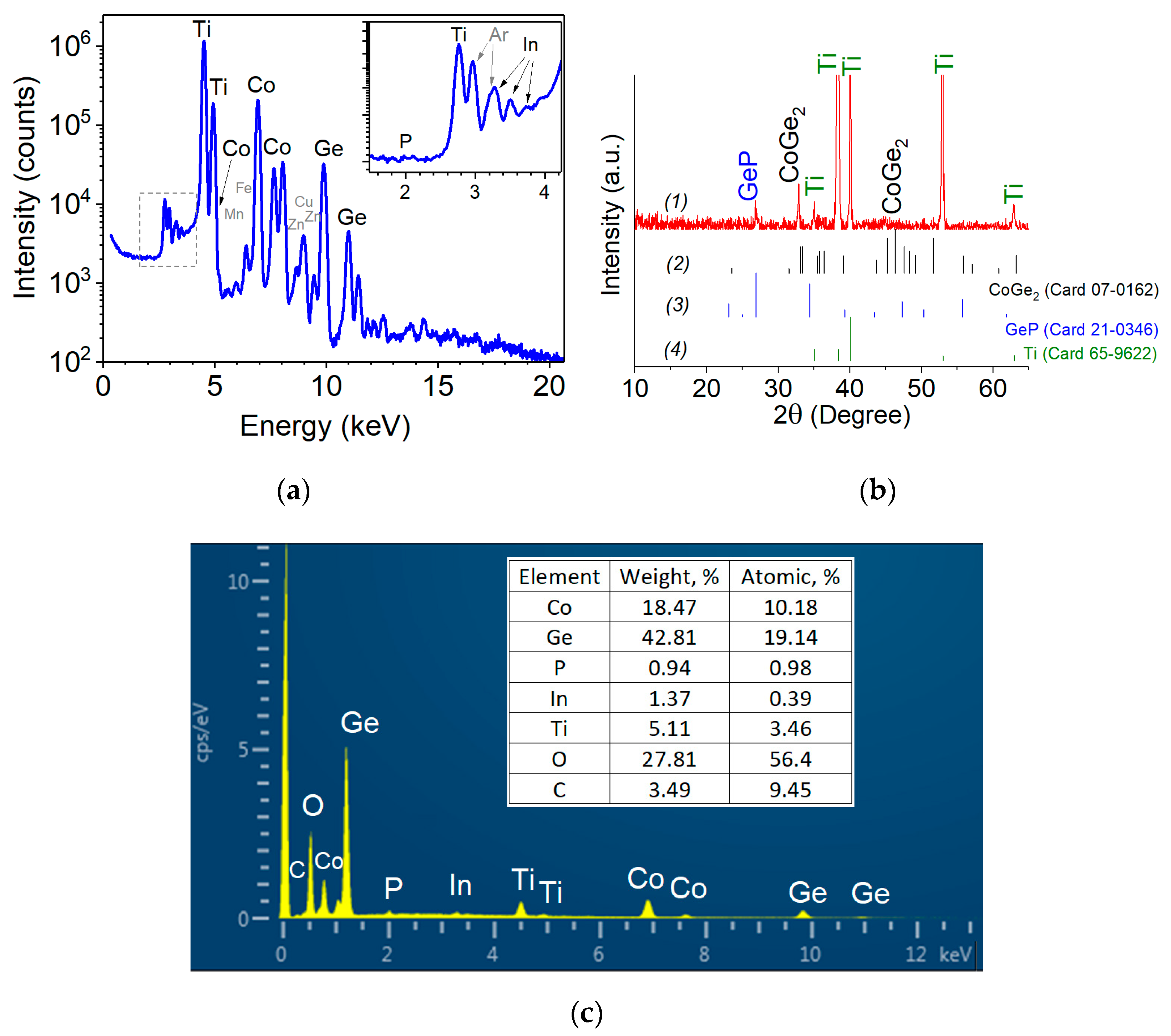
Figure 2.
SEM images of Ge-Co-P nanostructures at various magnifications: (a,b)—frontal image; (c,d)—cross section image.
Figure 2.
SEM images of Ge-Co-P nanostructures at various magnifications: (a,b)—frontal image; (c,d)—cross section image.
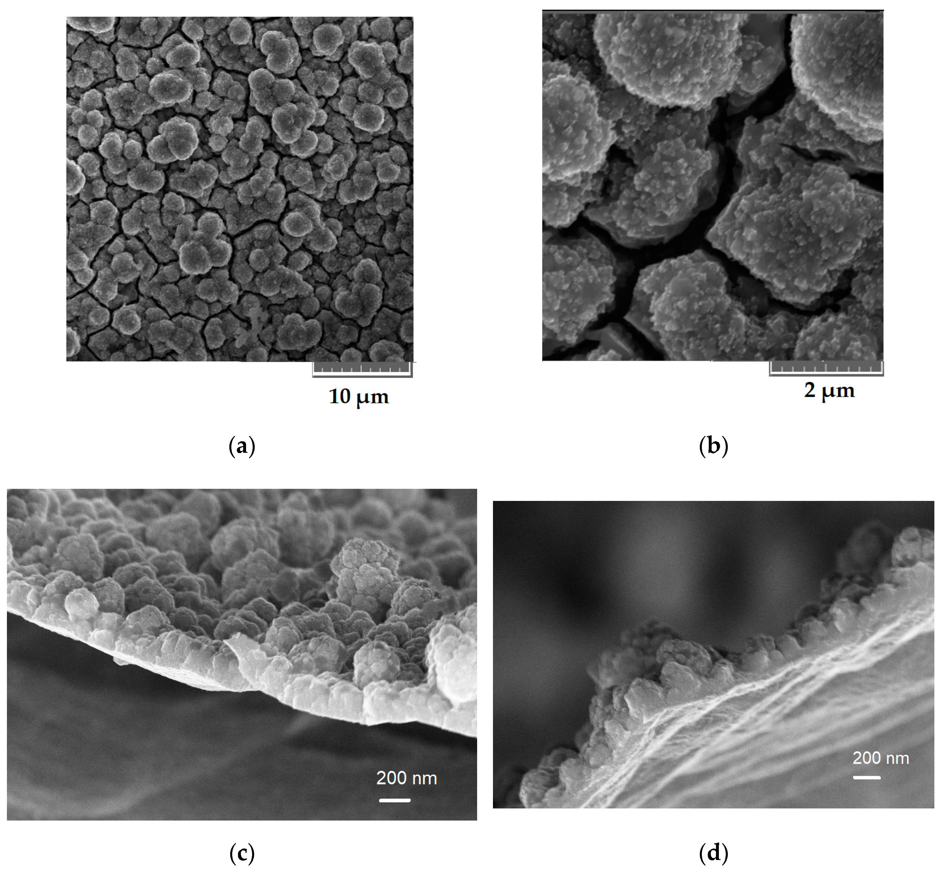
Figure 3.
(a) CVs for CoGe2P0.1 at two scan rates; (b) CVs of the lithium insertion/extraction into/from Ge-Co nanostructure.
Figure 3.
(a) CVs for CoGe2P0.1 at two scan rates; (b) CVs of the lithium insertion/extraction into/from Ge-Co nanostructure.
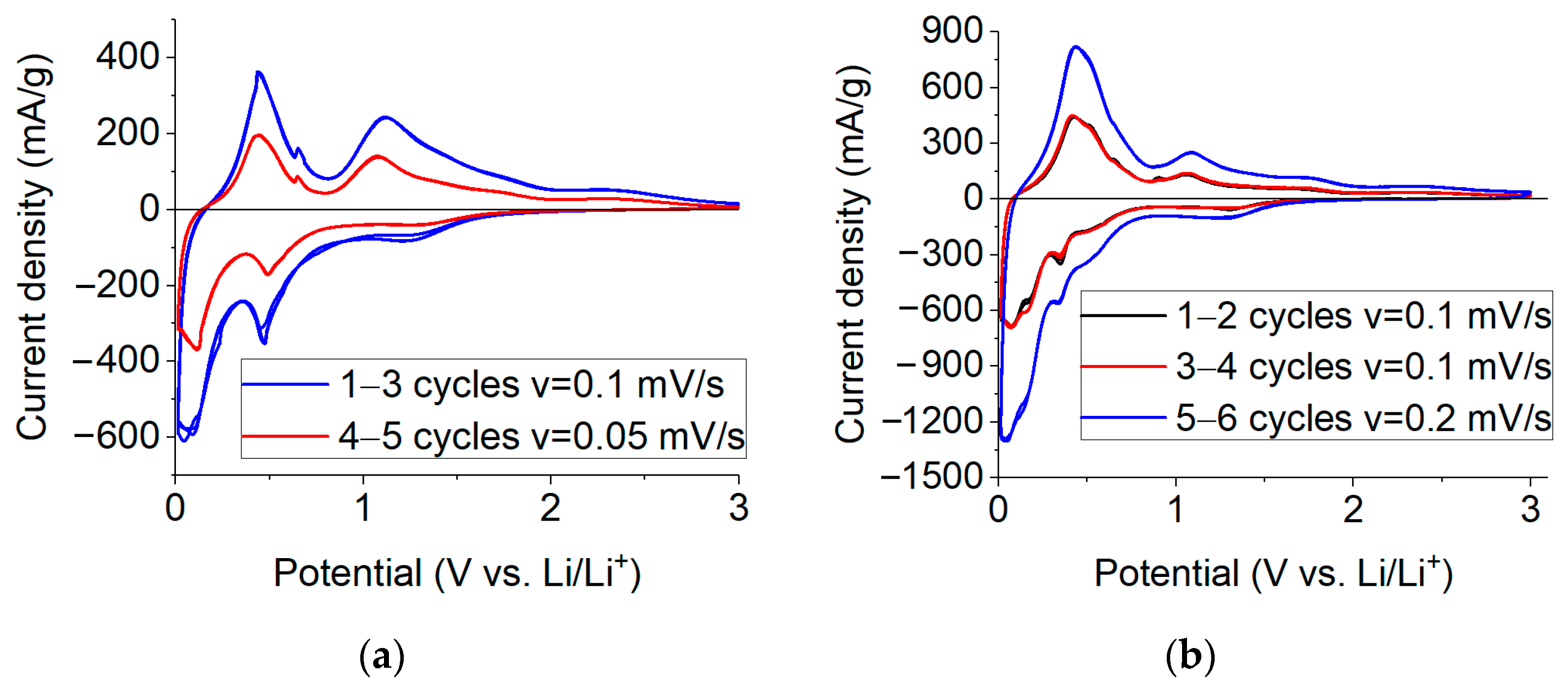
Figure 4.
Charge and discharge curves for sodium insertion/extraction into/from CoGe2P0.1 at various current densities.
Figure 4.
Charge and discharge curves for sodium insertion/extraction into/from CoGe2P0.1 at various current densities.
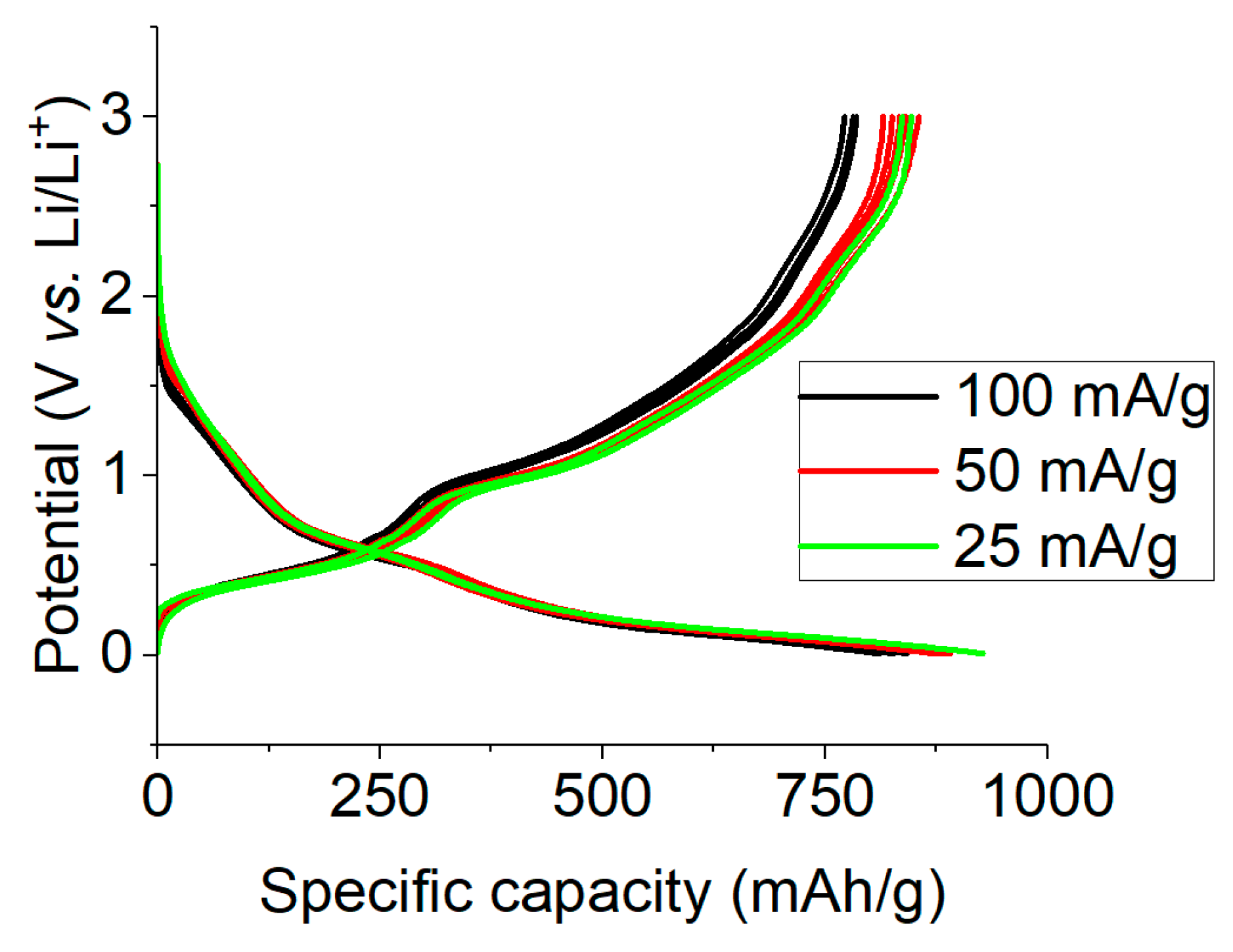
Figure 5.
(a) CVs for sodium insertion/extraction into/from CoGe2P0.1 at two scan rates; (b) charge and discharge curves for sodium insertion/extraction at various current densities.
Figure 5.
(a) CVs for sodium insertion/extraction into/from CoGe2P0.1 at two scan rates; (b) charge and discharge curves for sodium insertion/extraction at various current densities.
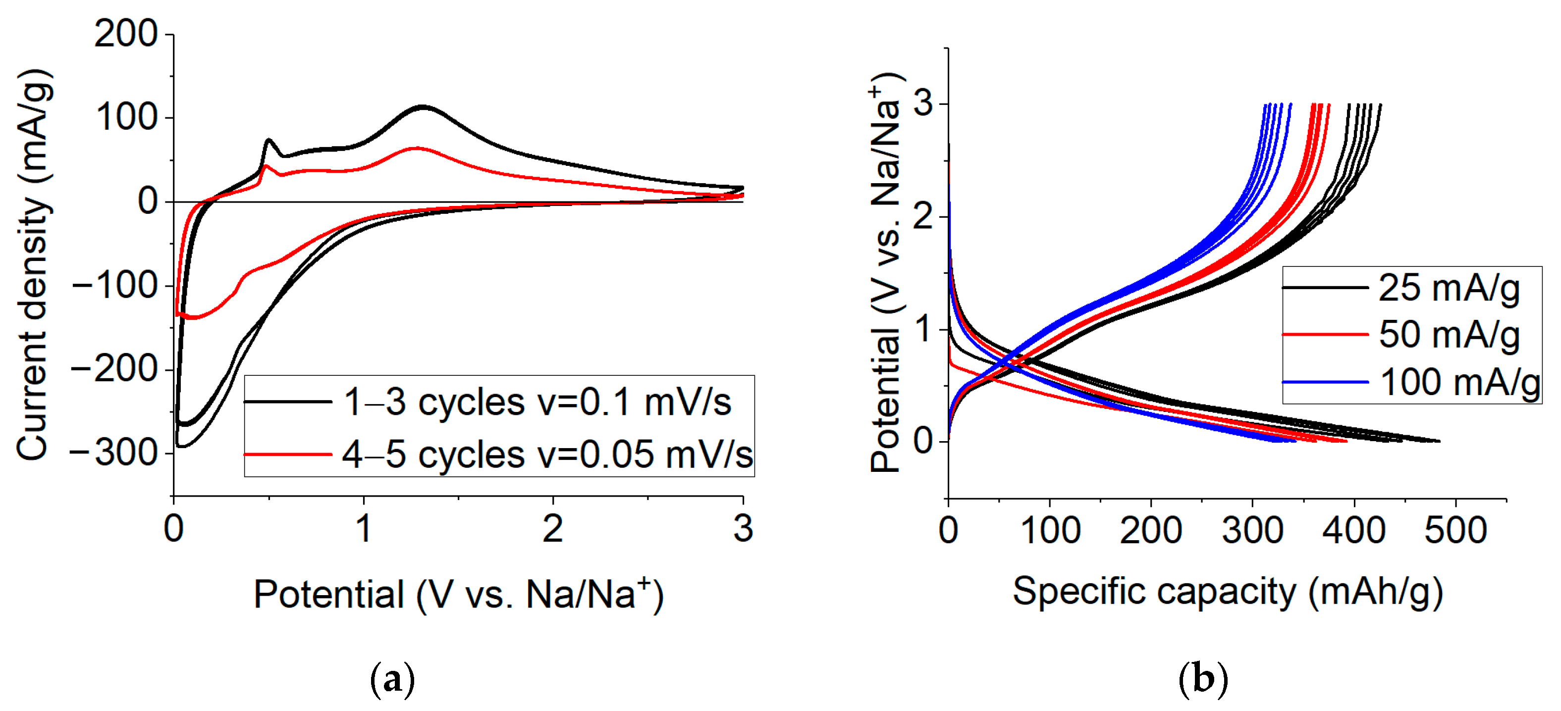
Figure 6.
(a) Nyquist plots of CoGe2P0.1 upon lithium (1) and sodium (2) insertion; (b) an equivalent circuit for simulating the impedance of CoGe2P0.1.
Figure 6.
(a) Nyquist plots of CoGe2P0.1 upon lithium (1) and sodium (2) insertion; (b) an equivalent circuit for simulating the impedance of CoGe2P0.1.

Figure 7.
Concentration dependence of potential for lithium (a) and sodium (b) insertion into CoGe2P0.1.
Figure 7.
Concentration dependence of potential for lithium (a) and sodium (b) insertion into CoGe2P0.1.
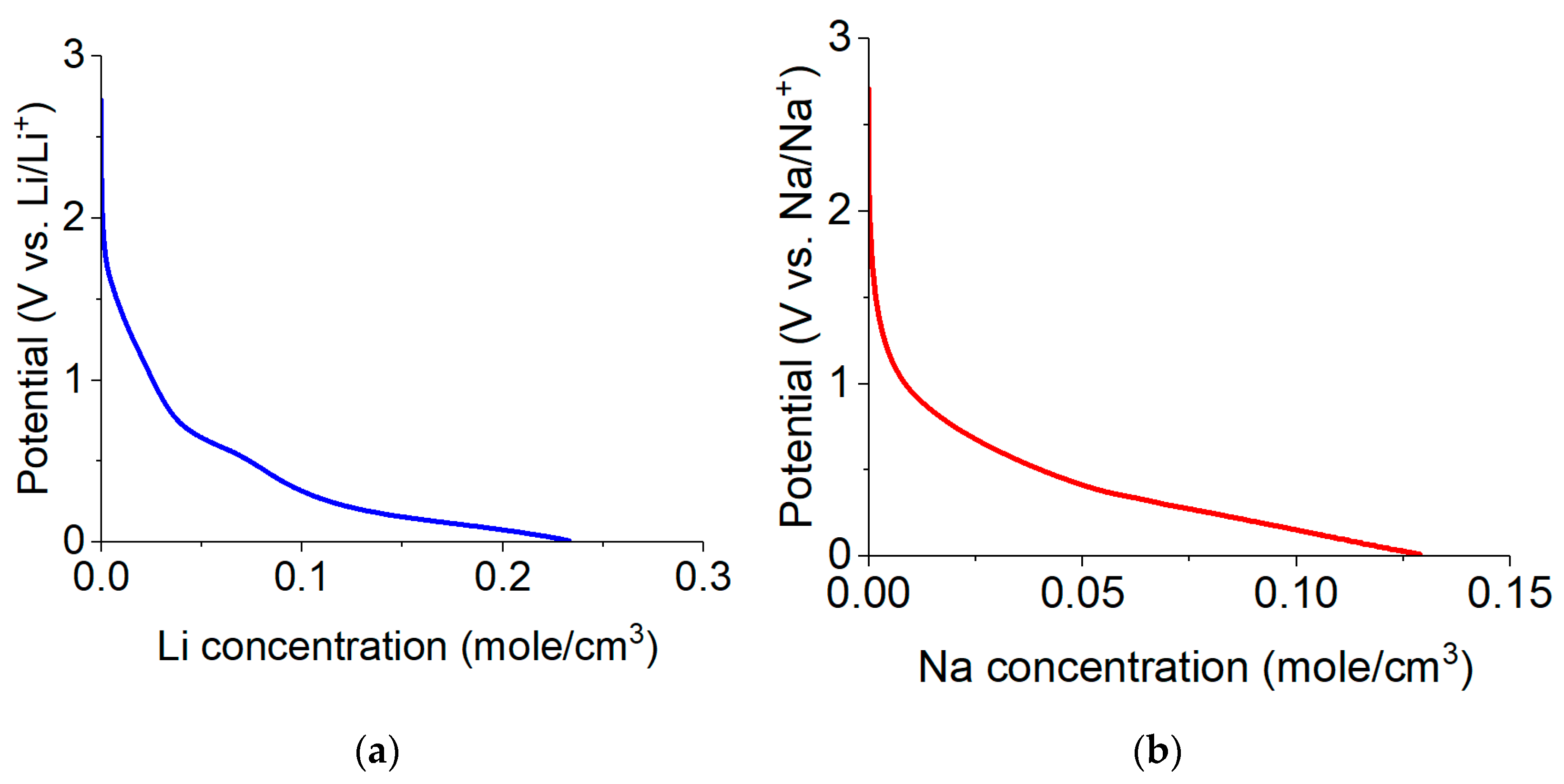
Figure 8.
The performances of CoGe2P0.1 upon long-term cycling at current density of 400 mA/g; (a) charge–discharge curves upon lithium insertion; (b) charge–discharge curves upon sodium insertion; (c) the capacity vs. current density dependence and Coulomb efficiency for insertion of lithium (black labels) and sodium (red labels).
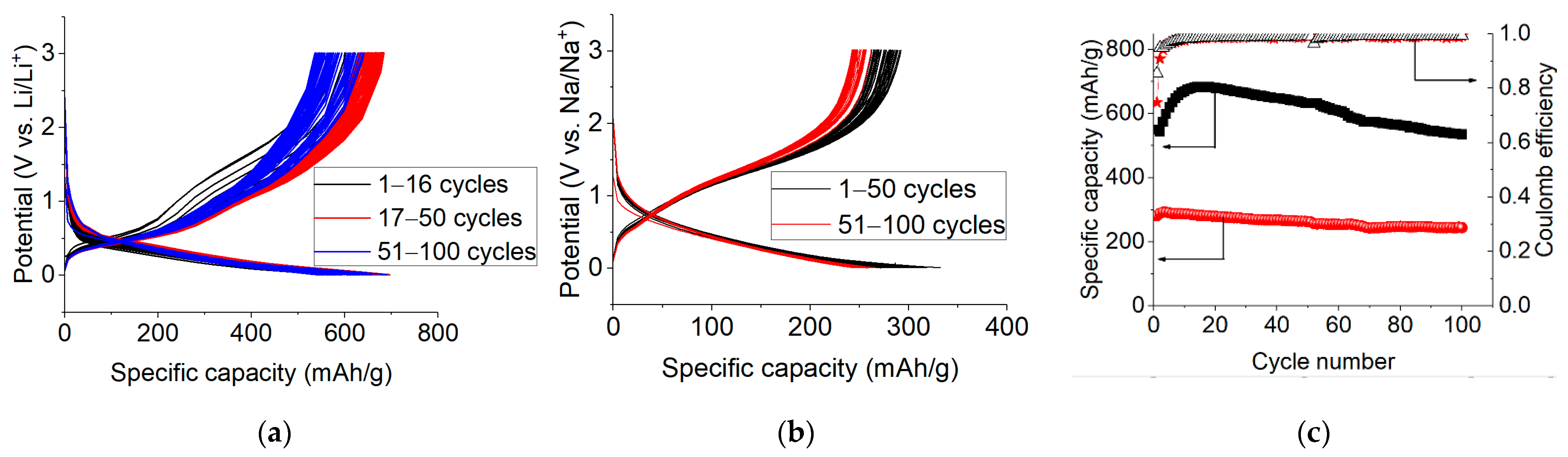
Figure 9.
The capacity vs. current density dependence for insertion of lithium (1) and sodium (2).

Figure 10.
Typical charge–discharge curves for laboratory pouch cell of the system “LiNi0.8Co0.15Al0.05O2—CoGe2P0.1”.
Figure 10.
Typical charge–discharge curves for laboratory pouch cell of the system “LiNi0.8Co0.15Al0.05O2—CoGe2P0.1”.


Table 1.
Equivalent circuit parameters, calculated from the impedance spectra during the insertion of lithium and sodium.
Table 1.
Equivalent circuit parameters, calculated from the impedance spectra during the insertion of lithium and sodium.
| R1, Ohm | R2, Ohm | Cf, F | R3, Ohm | Cdl, F | W, Ohm/s0.5 | |
|---|---|---|---|---|---|---|
| 3.76 | 5.19 | 3.82 × 10⁻⁶ | 76.29 | 2.79 × 10⁻⁶ | 40.66 | Li |
| 5.65 | 5.49 | 3.93 × 10⁻⁵ | 165.1 | 2.68 × 10⁻⁵ | 94.18 | Na |
Publisher’s Note: MDPI stays neutral with regard to jurisdictional claims in published maps and institutional affiliations. |
© 2022 by the authors. Licensee MDPI, Basel, Switzerland. This article is an open access article distributed under the terms and conditions of the Creative Commons Attribution (CC BY) license (https://creativecommons.org/licenses/by/4.0/).
Share and Cite
MDPI and ACS Style
Kulova, T.L.; Skundin, A.M.; Gavrilin, I.M.; Kudryashova, Y.O.; Martynova, I.K.; Novikova, S.A. Binder-Free Ge-Co-P Anode Material for Lithium-Ion and Sodium-Ion Batteries. Batteries 2022, 8, 98. https://doi.org/10.3390/batteries8080098
AMA Style
Kulova TL, Skundin AM, Gavrilin IM, Kudryashova YO, Martynova IK, Novikova SA. Binder-Free Ge-Co-P Anode Material for Lithium-Ion and Sodium-Ion Batteries. Batteries. 2022; 8(8):98. https://doi.org/10.3390/batteries8080098
Chicago/Turabian StyleKulova, Tatiana L., Alexander M. Skundin, Il’ya M. Gavrilin, Yulia O. Kudryashova, Irina K. Martynova, and Svetlana A. Novikova. 2022. "Binder-Free Ge-Co-P Anode Material for Lithium-Ion and Sodium-Ion Batteries" Batteries 8, no. 8: 98. https://doi.org/10.3390/batteries8080098
Note that from the first issue of 2016, this journal uses article numbers instead of page numbers. See further details here.