Article

A Novel Synchronized Multiple Output DC-DC Converter Based on Hybrid Flyback-Cuk Topologies

by
Khaled A. Mahafzah
1,*,
Mohammad A. Obeidat
1,2,
Ali Q. Al-Shetwi
3 and
Taha Selim Ustun
4,*
1
Department of Electrical Engineering, Al-Ahlyyia Amman University, Amman 19328, Jordan
2
Electrical Power and Mechatronics Engineering Department, Tafila Technical University, Tafila 66110, Jordan
3
Electrical Engineering Department, Fahad Bin Sultan University, Tabuk 71454, Saudi Arabia
4
Fukushima Renewable Energy Institute, AIST (FREA), National Institute of Advanced Industrial Science and Technology (AIST), Koriyama 963-0298, Japan
*
Authors to whom correspondence should be addressed.
Batteries 2022, 8(8), 93; https://doi.org/10.3390/batteries8080093
Submission received: 8 July 2022 / Revised: 10 August 2022 / Accepted: 12 August 2022 / Published: 15 August 2022
(This article belongs to the Collection Recent Advances in Battery Management Systems)

Abstract

:
This paper proposes a new hybrid flyback-Cuk (HFC) converter. The new converter consists of a single switch, a single isolated input, and dual output based on flyback and Cuk topologies. The new HFC topology is proposed to reduce switching losses and improve the duty cycle range over which voltage can be stepped down, which would ultimately lead to an increase in efficiency. For step-down capability, the traditional single topologies (flyback or Cuk) require a less than 50% duty cycle. The low duty cycle of conventional converters leads to low operational efficiency. Therefore, the developed HFC can operate at a duty cycle of up to 85% for the same capability. The analysis, derivations, design, and simulation of the proposed HFC are thoroughly discussed for two different applications at two different power levels. The simulation results are obtained using MATLAB 2020a. The developed HFC’s efficiency as a function of the duty cycle is plotted, which reaches 89%, representing a significant efficiency improvement. The proposed converter can supply and absorb power simultaneously, giving it a significant edge over other converters. It is suitable for energy conversion and storage systems, such as renewable energy systems and electric vehicles (EV). To show the effectiveness and validate the new topology proposed, an EV along with battery energy storage (BES), is applied to charge (EV) and recharge (BES) simultaneously. The simulation results of 1.5 kW of HFC-PFC over the universal voltage range show that the proposed HFC can achieve a high power factor up to 97.5% at 260 Vrms. Moreover, the total harmonics distortion is measured between 36.25 and 27.69%. Thus, the results can achieve all required functions efficiently with minimum losses at a high range of duty cycles.

1. Introduction

The rapid developments in power electronics significantly impact many industrial fields. Converters, such as DC-DC, DC-AC, and AC-DC are widely used to drive and control various electrical equipment in many applications, such as renewable energy systems, electric vehicles, robotic systems, micro-grids, and lighting systems [1,2,3,4]. There are many research efforts in this field to increase efficiency, reduce power losses and improve control so that the system can operate accurately.
According to the operation principle, DC-DC converters can be divided into three main types: hard switched, soft switched, and linear mode. DC-DC converters can be either isolated or non-isolated converters. Isolated DC-DC converters equipped with an inductor include flyback, buck, boost one-key, half-bridge, full-bridge, and multi-switch push-pull. Non-isolated DC-DC converters include Cuk, buck, boost, and buck/boost converters [5,6,7]. These converters have many applications in electrical systems. The design of these converters is very important, as it directly affects the overall efficiency. The switch is one of the most critical parts of these converters because it allows for the ability to control the time and amount of energy transfer. A suitable control signal is utilized to control this switch by opening and closing it based on the duty cycle, which the designer can select for efficient operation. For example, a buck converter has some advantages [6], such as the fact that it is a very simple converter with a step-down capability. Additionally, the output inductor is placed at the load side, which filters the output current. Despite these advantages, the buck converter has many disadvantages, such as it having a very slow response to input voltage changes, the fact that a separated loop must do current limiting, and it requires a high side driver [6,7].
A Cuk converter is a single switch, non-isolated DC-DC converter that can step up or down the input voltage with a reverse output voltage polarity. It combines the advantages of buck and boost converters in terms of filtering both input and output sides. The energy in the Cuk converter is transferred via a coupling capacitor, and the current mode in the converter determines the control requirements [8,9,10]. On the other hand, a flyback converter is an isolated single switch DC-DC converter. It can be used to step up or down the input voltage while maintaining the same input polarity to ensure that the switch channel is totally opened when the switch is off. This converter is very popular thanks to its simple design, lower cost, high output voltage and efficiency [11,12,13]. Figure 1 shows the block diagram for both flyback and Cuk converters. The flyback converter transfers forward energy to the load, while the Cuk converter reverses the energy back to the energy storage system.
Many studies were conducted to improve the operation and efficiency of these converters. For instance, the authors in [14] proposed a dual converter consisting of both a single-ended primary inductor converter (SEPIC) and Cuk converters to enhance the voltage gain and produce two output voltages that can be used for multiple voltage power supplies. In [15], a multi-input single-output converter that combines both boost and buck/boost converters for better voltage gain is introduced.
In addition, the authors in [16] proposed a flyback-Cuk topology-integrated DC-DC converter for negative output voltage. This converter attains a very high gain that can be used for grid interfacing. However, this topology has some drawbacks: (1) The applications of the negative output voltage are limited. (2) In this topology, three filter capacitors are used on the output side; thus, the energy balance between these capacitors will be more complex, and the cost will be increased as well. (3) Moreover, the proposed topology increases the voltage gain; hence, it offers only a state of step-up functionality. (4) Finally, this topology utilized an excessive number of components, increasing design complexity and cost.
Recently, some studies proposed hybrid DC-DC converter topologies to overcome the drawbacks of conventional converters. For instance, a buck-boost/flyback hybrid converter is applied in [17] to enhance the battery charging and discharging functions. In addition, this hybrid topology has better conversion efficiency and lower weight than conventional ones. Authors in [18] proposed a hybrid boost-boost-flyback topology to achieve a high voltage gain without sacrificing the efficiency of the converter. A hybrid topology (boost-flyback/flyback) was introduced for the same purpose in [19]. The presented results show this hybrid converter’s ability to attain high voltage gain with little voltage stress via reducing the transformer turn ratio. A soft-switched boost-integrated flyback converter with high-gain voltage is applied to obtain highly efficient power conversion for a grid-tied inverter in a solar photovoltaic system [20]. In this topology, the voltage stress across the switches is restrained substantially under the voltage output. The results of this study demonstrate effective conversion at the DC-DC converter stage and high-quality power injection at the DC-AC inverter stage, respectively. However, the accurate reduction in switch losses was not considered in the studies above because they include several switches. Furthermore, although these hybrid converters achieved high-voltage gain, no case study was presented to show that the voltage gain status is achieved at high duty cycles. Additionally, in these studies, the conversion efficiency at a high duty cycle is not taken into consideration or overlooked. On the other hand, a converter that can supply and receive energy simultaneously is not sufficiently covered in the literature, which needs further investigation.
In this regard, a detailed review of power converters and the current state of the art, including bidirectional, resonant, and multilevel converters, is explained in detail by [21]. In this study, the authors provide the advantages and disadvantages of each. Consequently, the authors recommend that a big challenge for the researchers in this field is to provide one converter that can do multiple functions simultaneously, as well as could deliver and store efficient energy. However, there is no hybrid flyback-Cuk DC-DC converter topology available in the literature that has a smaller number of components and can simultaneously perform multiple functions.
Therefore, this study proposes a novel hybrid flyback-Cuk (HFC) DC-DC converter with re-charging capability for energy conversion systems to overcome the reported drawbacks and fill in this important knowledge gap. The proposed topology will hopefully lead to the increased efforts of engineers and scientists to do more research and improvements in terms of control methods, power quality issues and apply different optimization techniques to select the best fit components for different applications, including hybrid energy systems (PV and wind) and EV systems. This is because the HFC can provide a forward and reverse energy flow. Additionally, the proposed HFC topology has fewer components than conventional converters, which leads to reduced manufacturing costs. The newly developed topology (HFC) has the following contributions to the current body of knowledge:
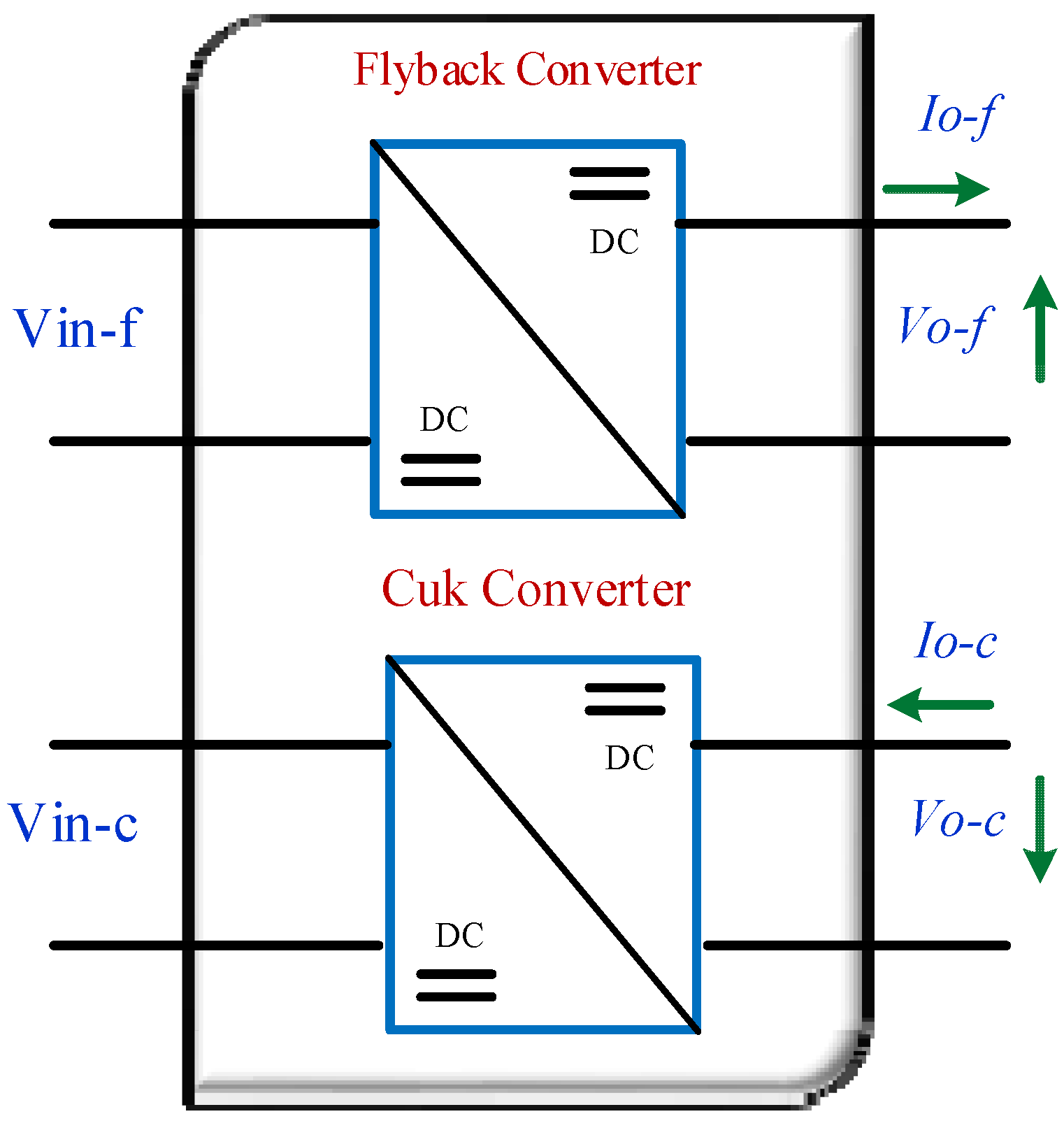
  • The proposed HFC has only one switch with single primary isolated input and dual outputs.
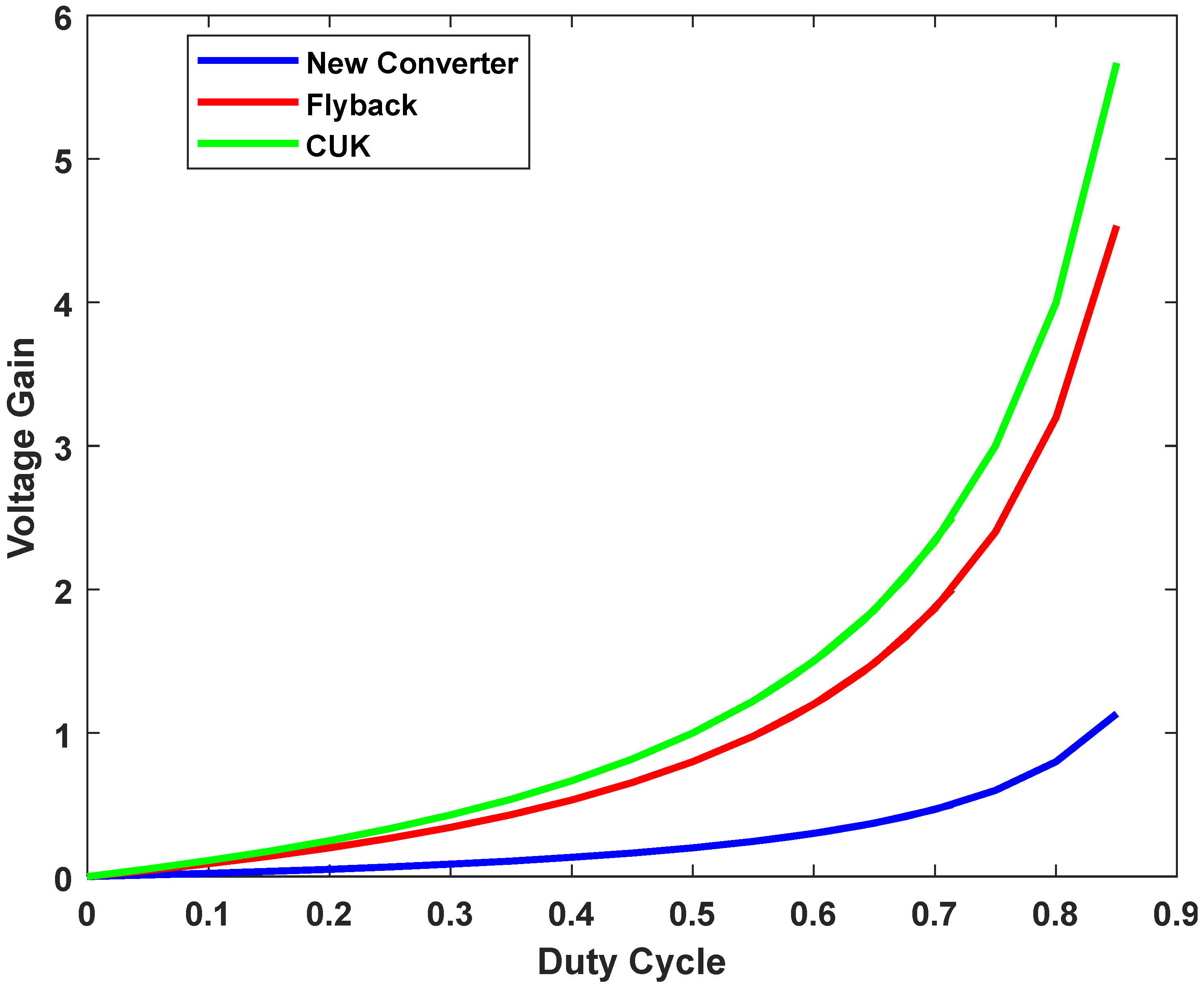
  • The voltage gain of HFC is enhanced by keeping it less than 1 for higher duty cycle values. Conventional flyback or Cuk converters experience a dramatic voltage gain increase after 50% duty cycles. Thus, HFC can be used for both step-up and step-down states.
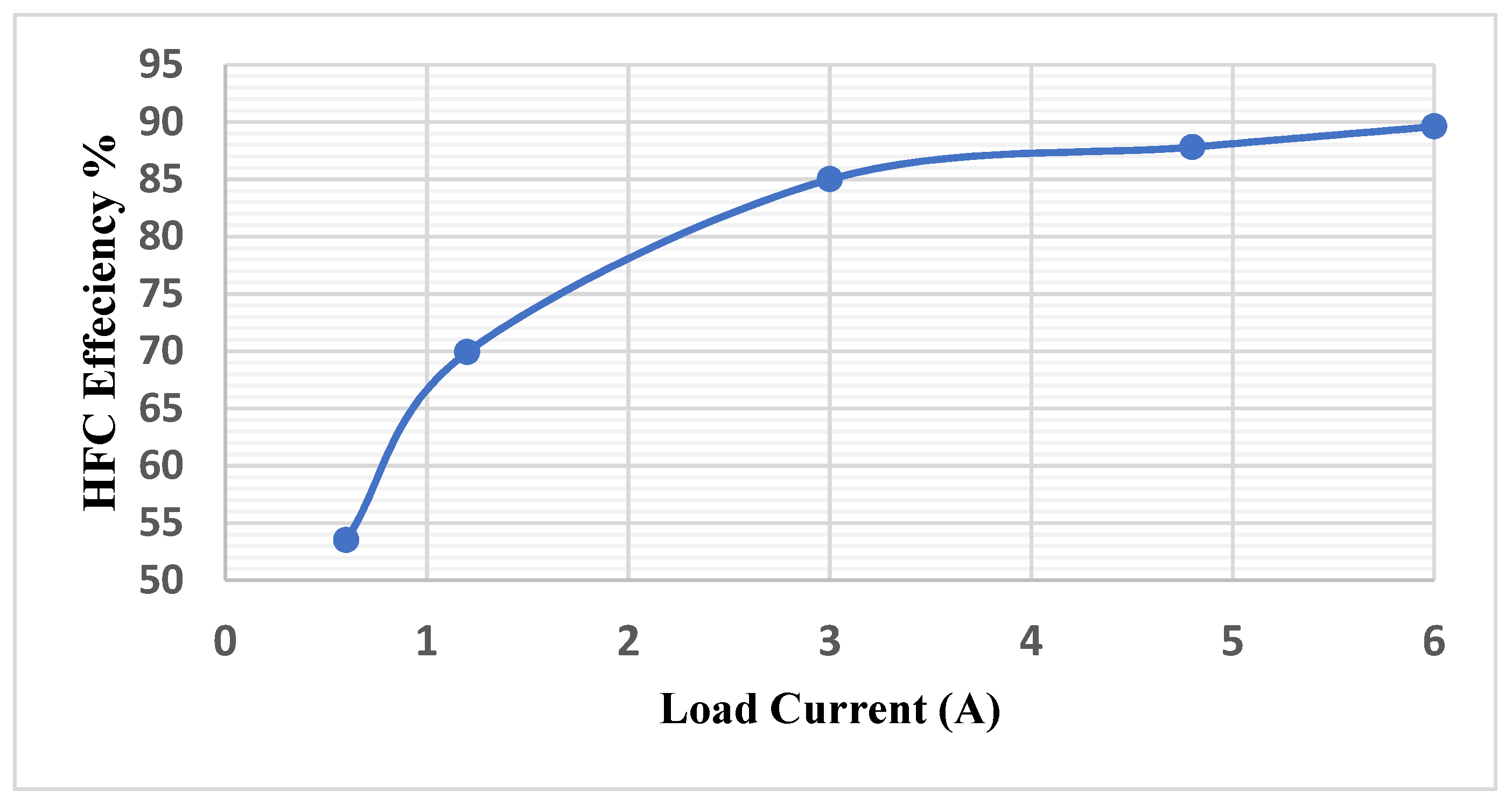
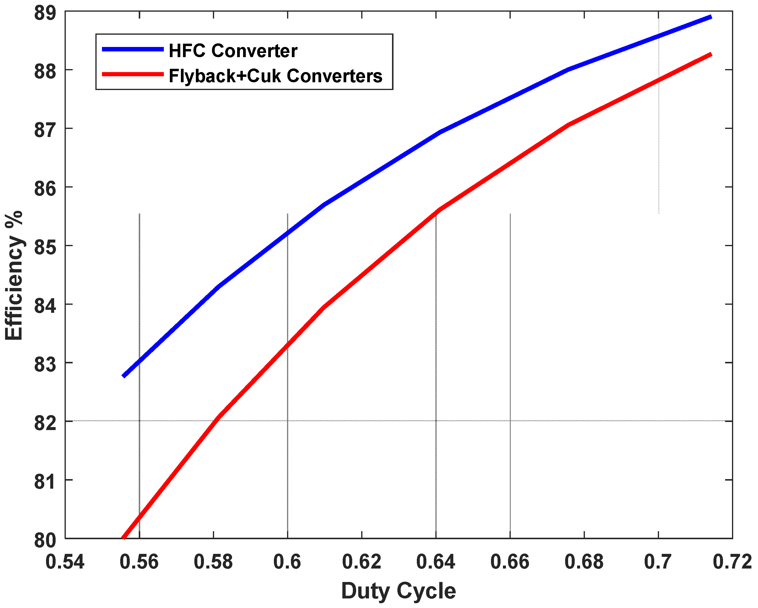
  • The switching losses for the switch are minimized. Hence, the efficiency of the proposed HFC is high and can reach around 90% for higher duty cycle values (e.g., 80% duty cycle).
  • The proposed HFC can supply and receive energy simultaneously, making it suitable for different applications of energy conversion systems.
  • An EV charger is used as a case study to demonstrate the efficacy of the proposed HFC. It can step down the voltage at high duty cycles, and simultaneous bidirectional operation was confirmed.
The rest of the paper is organized as follows: Section 2 presents the analysis of the proposed converter and its operation. Section 3 discusses the simulation results along with efficiency considerations. Section 4 investigates a case study of using the proposed HFC as an EV charger. Finally, Section 5 draws conclusions and provides further insights.

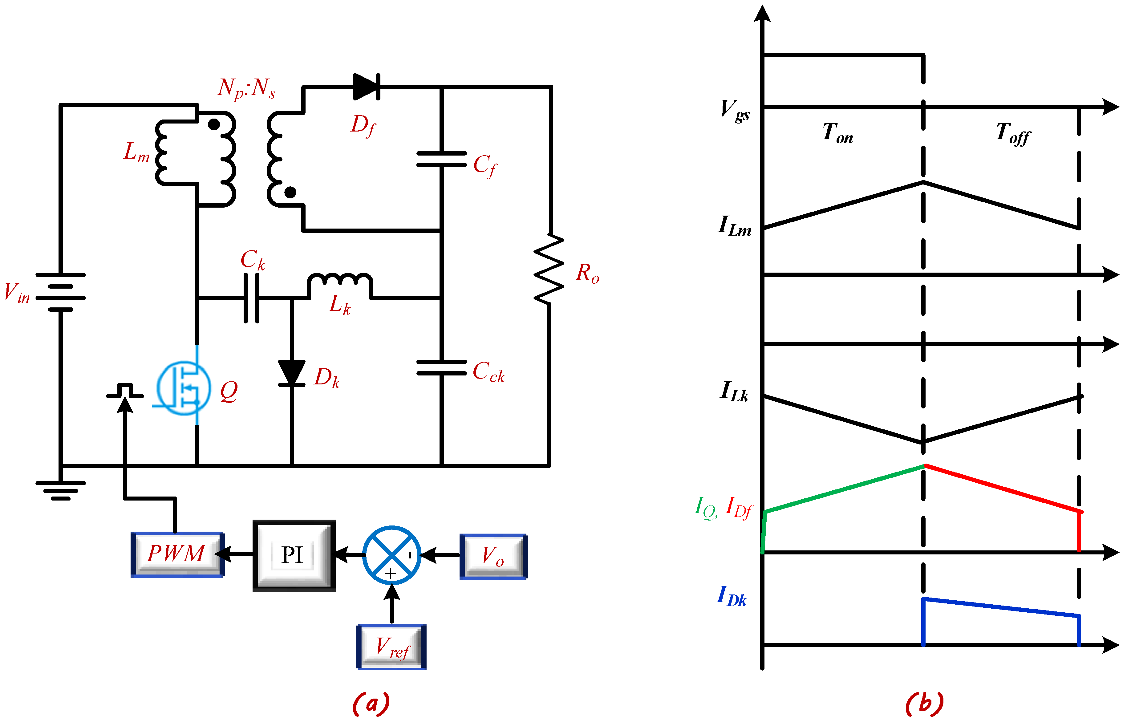
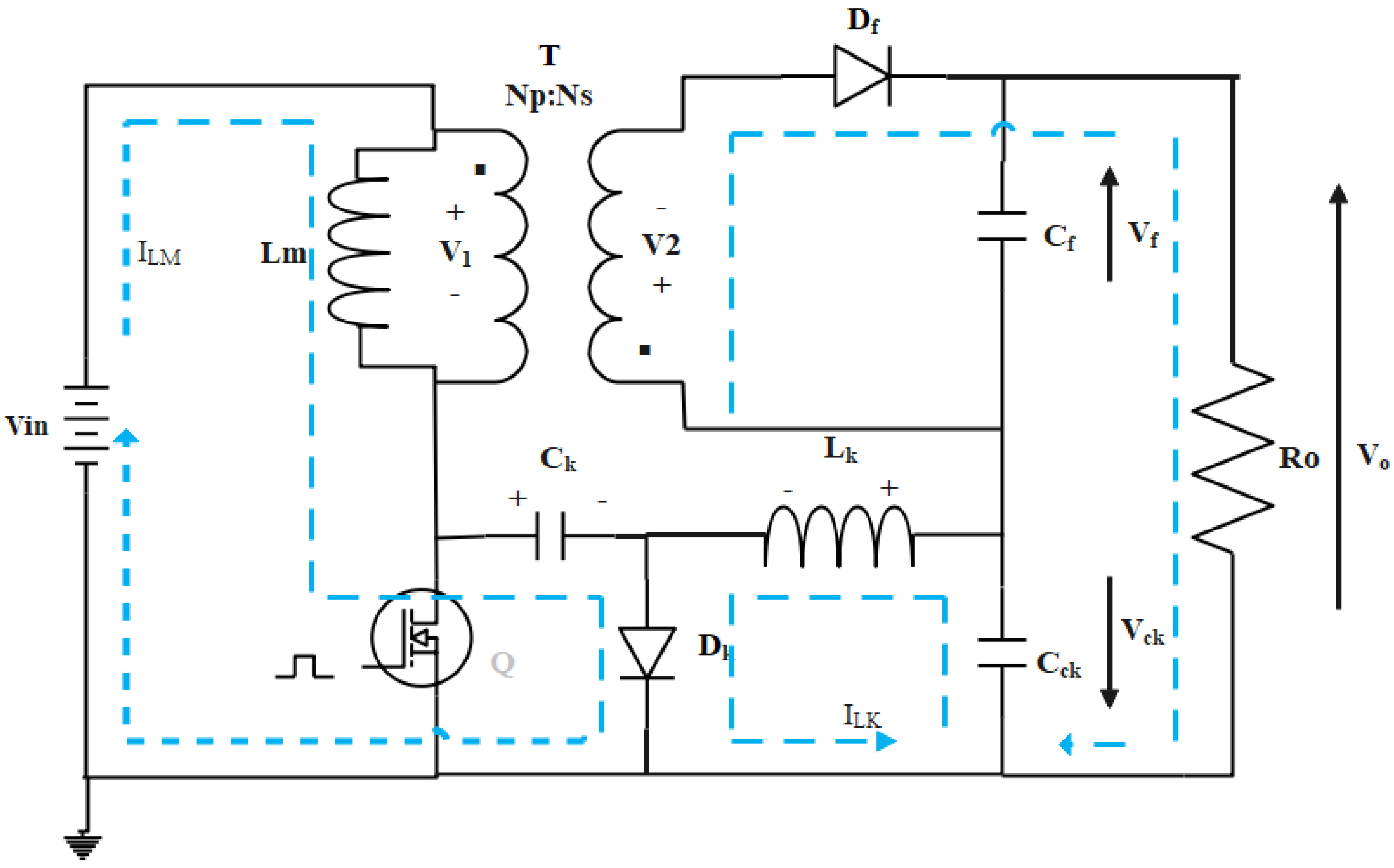
2. Analysis of the Proposed HFC Converter

The proposed HFC consists of two converters. The first one is the flyback converter, and the second one is the Cuk converter. Both converters share the same input components (DC power supply, the primary side of the transformer, and the switch Q). The output of each separate converter is connected in series. Therefore, the output voltage across the load is the difference between the flyback output voltage and the Cuk output voltage. The proposed converter is controlled by a voltage control loop (PI controller). The controller output produces the relative duty cycle to control the switch Q. Figure 2a illustrates the proposed HFC converter, and Figure 2b shows its key waveforms in continuous current mode (CCM).
The analysis of the proposed HFC converter can be discussed based on the following assumptions:
  • In steady-state, the average inductor voltage is zero.
  • In steady-state, the average capacitor current is zero.
  • In steady-state, the average value of the Cuk coupling capacitor (Ck) is Vin + Vo.
Two operation modes of the proposed HFC converter are considered according to the state of the switch Q, whether it is ON or OFF. These two modes are:
A. 
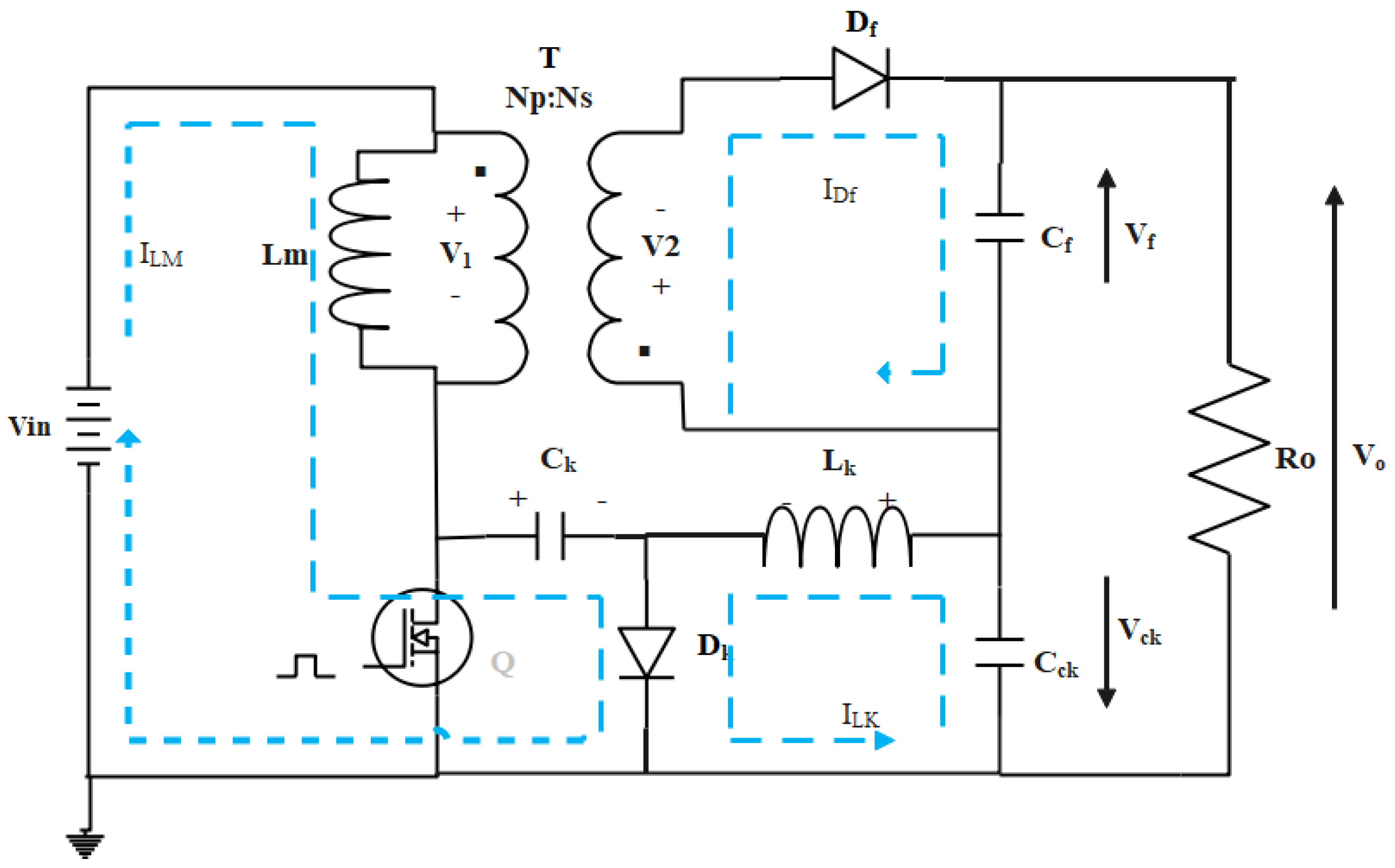
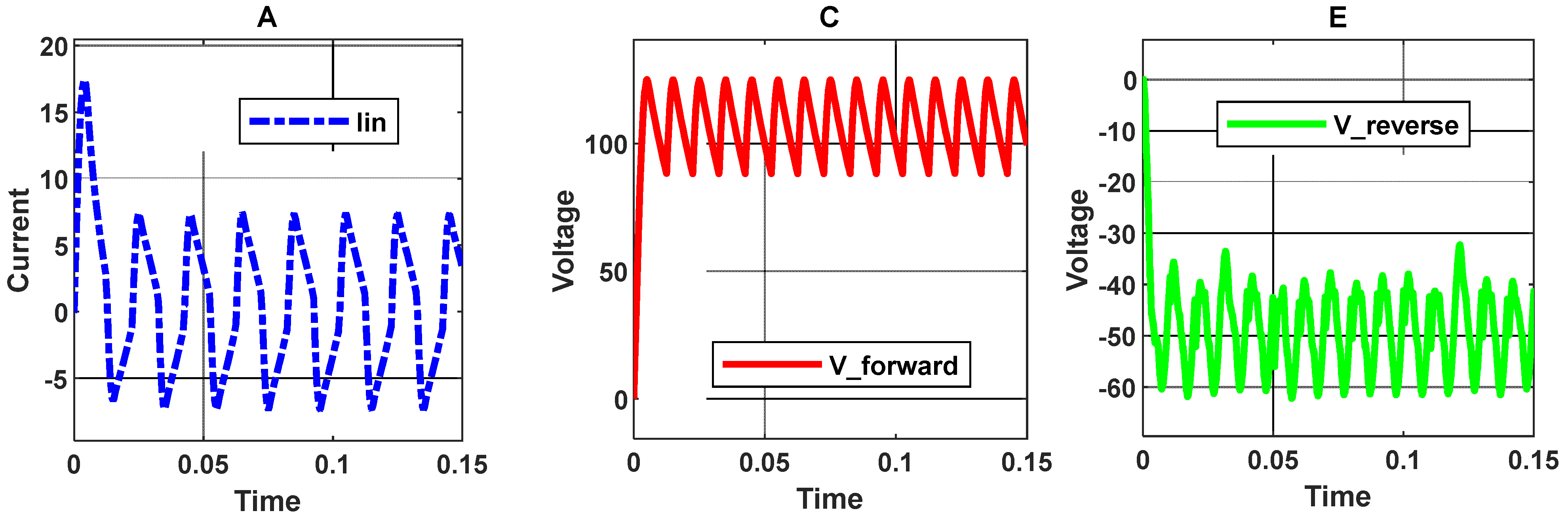
When Q is ON: Both the flyback output diode (Df) and the Cuk diode (Dk) are reverse biased. Figure 3 illustrates the current and voltage directions for the ON state. During this period, the magnetization inductance (Lm) is being energized from the input voltage source. Therefore, the rate of change of current in the magnetization inductance is linearly increased according to the following equation:
d I L m d t = V i n L m
The voltage across the inductor Lk is (VckVo), and the rate of change of its current is given by:
d I L k d t = ( V c k V o ) L k
where Vck is the Cuk stage output voltage as given below in Equation (3):
V c k = V i n D Q ( 1 D Q )
B. 
When Q is OFF: Diodes (Df) and (Dk) are conducting. Figure 4 shows the currents and voltage directions for the OFF state. During this mode, Lm is being de-energized by (−V1). The rate of change of current in the magnetization inductance is given by:
d I L m d t = V 1 L m
Moreover, Lk is also de-energized by the voltage Vck, and the rate of change of the current in the inductor Lk is given by:
d I L k d t = V c k L k
From Equations (1)–(5), it can be observed that the rate of change in all inductor currents depends on the input/output voltages and inductor values. The duty cycle of the proposed HFC converter (DQ) can be calculated as:
V o = V f V c k
V o = N s N p V i n D Q 1 D Q D Q 1 D Q V i n
Using Equations (6) and (7), then,
D Q = N p V o N p V o + V i n ( N s N p )
From Equation (7), the voltage gain of the proposed HFC converter can be derived as:
V G H F C = V o V i n = | N s N p N p D Q 1 D Q |
From Equation (9), it can be seen (if Ns < Np) that the HFC is a step-down converter. Figure 5 displays the voltage gain versus the duty cycle for HFC, flyback, and Cuk converters. It can be seen that; the lowest voltage gain (blue curve) is HFC gain compared with the other converters’ gains for flyback (red curve) and Cuk (green curve).
Moreover, to ensure step-down functionality of the HFC converter, the voltage gain must be less than 1, i.e., V o V i n < 1. The HFC converter is operated in step-down conditions for a duty cycle of up to 82%. While both flyback and Cuk converters are operated in step-down conditions at limited duty cycle values lower than D = 50%, then for D > 50%, the voltage gain increases dramatically, and the output voltage is boosted up.

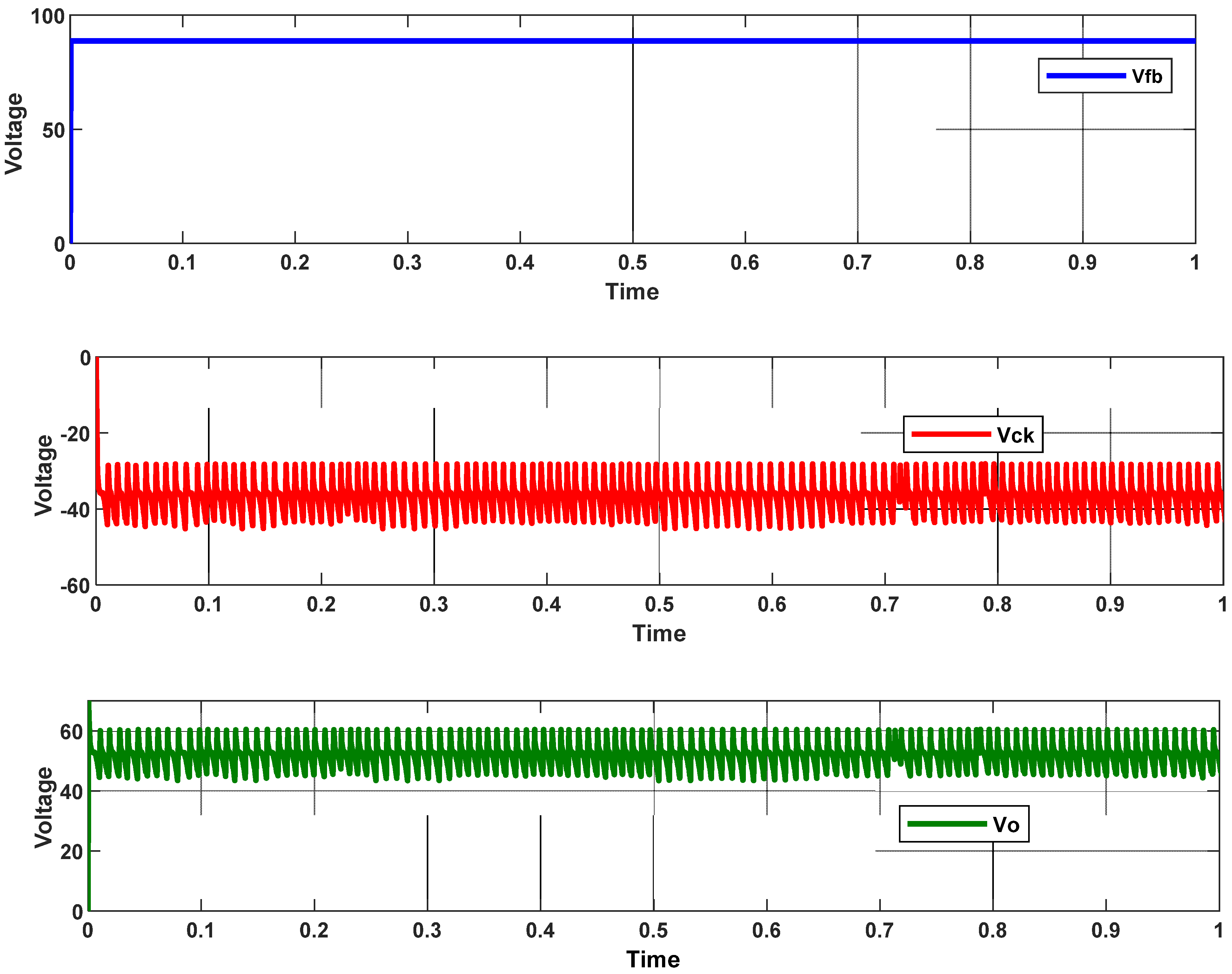
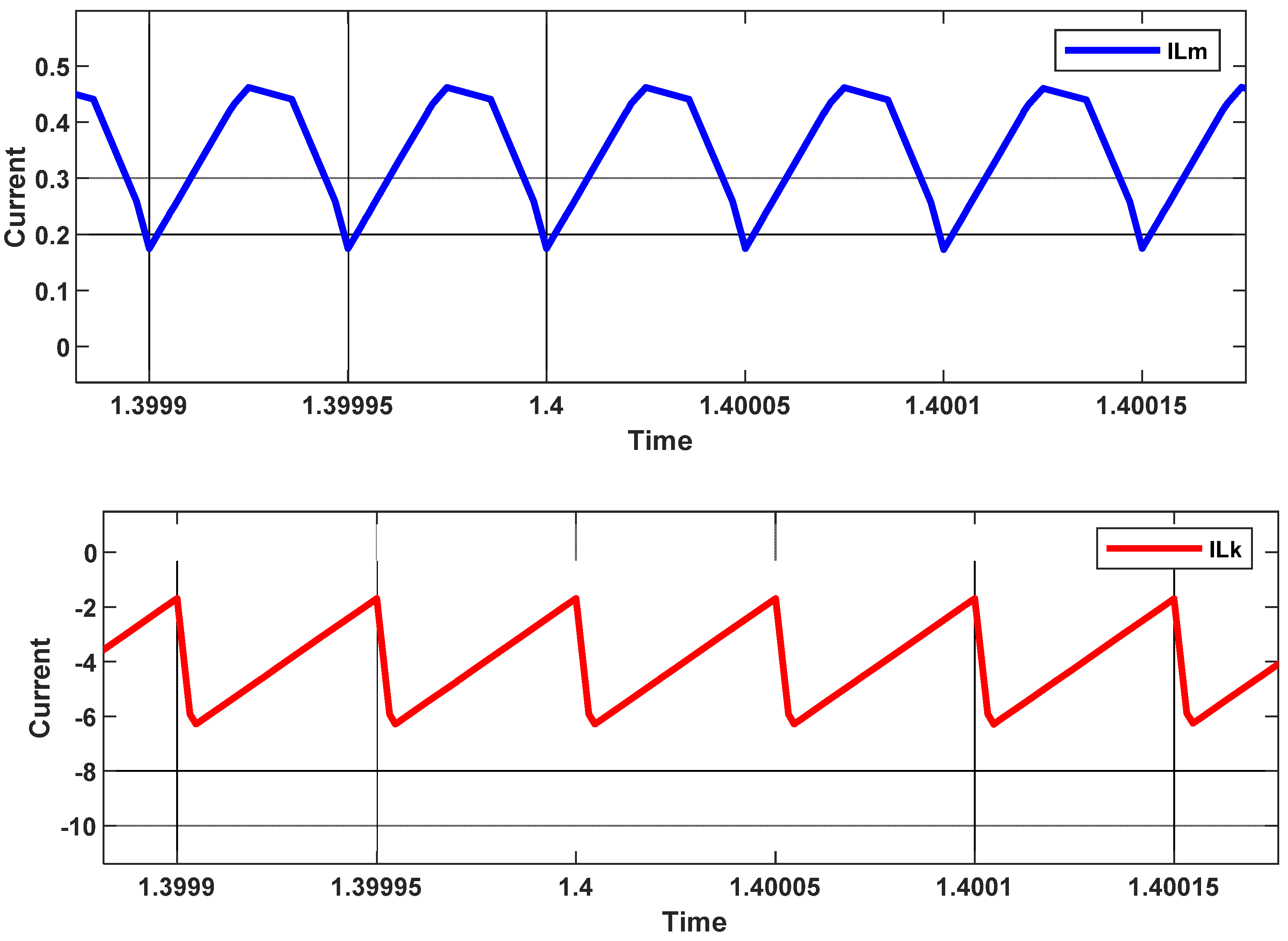
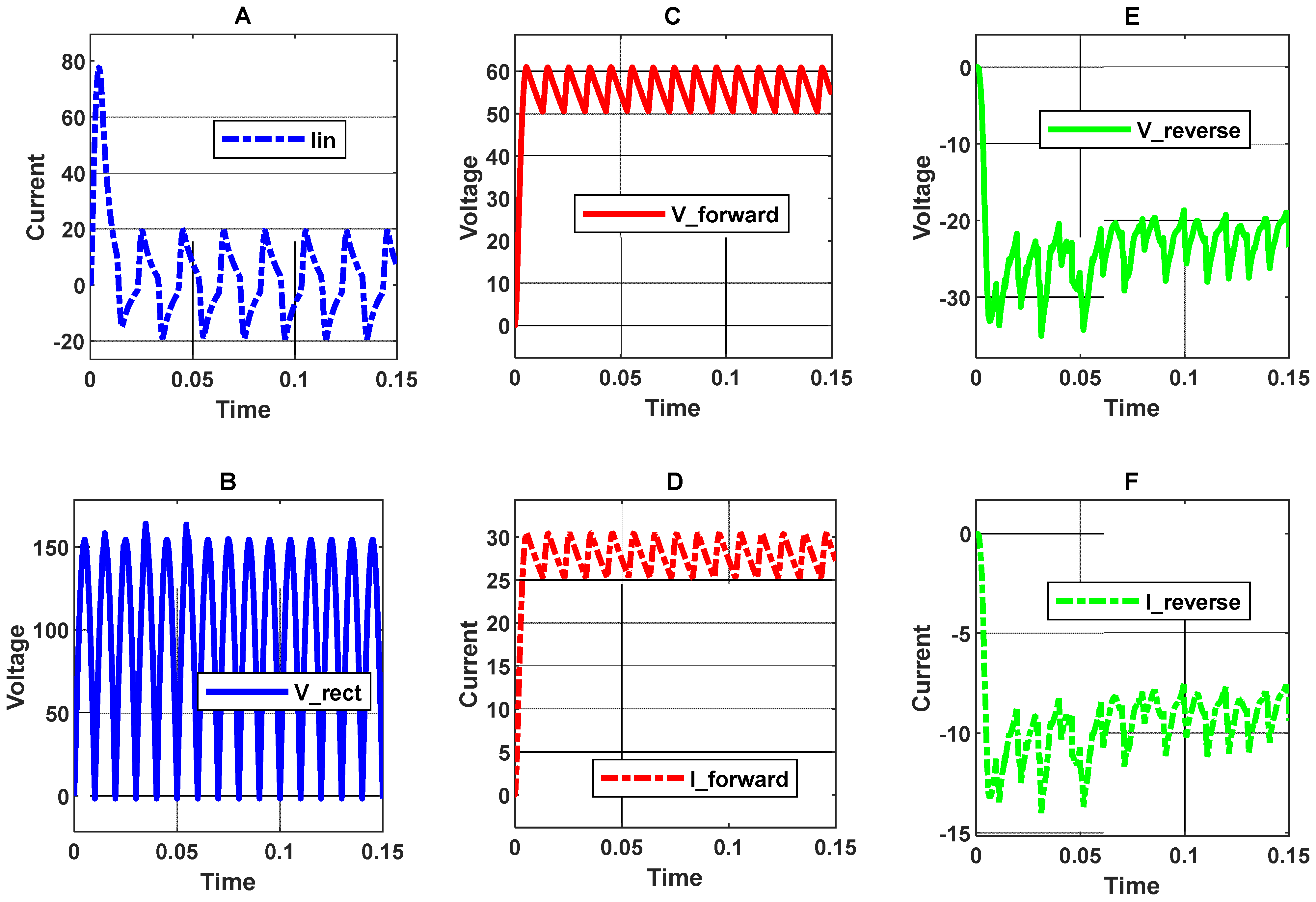
3. Simulation Results

To verify the results, Matlab/Simulink R2020a is used. The selected solver is an ordinary differential equation (ode23tb) with a relative tolerance of 10−3, and a maximum step size of 25 µs is selected. The simulation time is set to 2 s to ensure that the proposed HFC converter eventually operates at a steady state.

3.1. Model Parameters

The HFC converter is basically designed to operate in CCM and feed a 300 W load at a switching frequency of 20 kHz. The passive parameters of HFC are calculated according to the following steps:
The magnetization inductance (Lm) is selected to minimize the current ripple on the primary side, thus, simplifying the design of the circuit’s EMI filter [22]. The minimum limit value for the inductance is:
L m m i n = ( 1 D Q ) 2 R o 2 f s
where fs is the selected switching frequency, and Ro is the output resistance. The output capacitance Cf is selected to minimize the output voltage ripple, determine the poles of the system modulator, and indicate the response of the supply to a sudden large change of the load current [23]. The minimum flyback output capacitance is:
C f m i n = D Q Δ V o V o R o f s
where, Δ V o V o is the desired output voltage ripple of the flyback stage. The transformer turns ratio ( N p / N s ) is chosen to limit the converter duty cycle to less than 50% for the flyback converter [23]. This will reduce the voltage stress on the flyback diode and the output capacitance. Then, the turns ratio becomes:
N p N s = V i n D Q m a x V f b ( 1 D Q m a x )
The Cuk inductances Lm and Lk are selected to reduce the complexity of the EMI filter [24]. The inductance values are given by:
L m , k = V o ( 1 D Q ) Δ I m , k f s
where ΔIm,k is the desired current ripple in Lm or Lk. The selected value for the common inductance Lm should be the maximum inductance value given by both Equations (10) and (13). The Cuk output capacitance Cck is designed to be:
C c k = Δ I L k 8 Δ V c k f s
To verify the topology, the proposed HFC converter is designed for low and medium power applications with a rated power of 300 W and 1.5 kW. Thus, after the rated power/input voltage/output voltage/switching frequencies are assigned, the other parameters are designed according to the presented equations. The design parameters are chosen to support the low power application and the derived equations that are part of the design itself.
Table 1 summarizes the parameters for the 300 W power application used in the simulation.

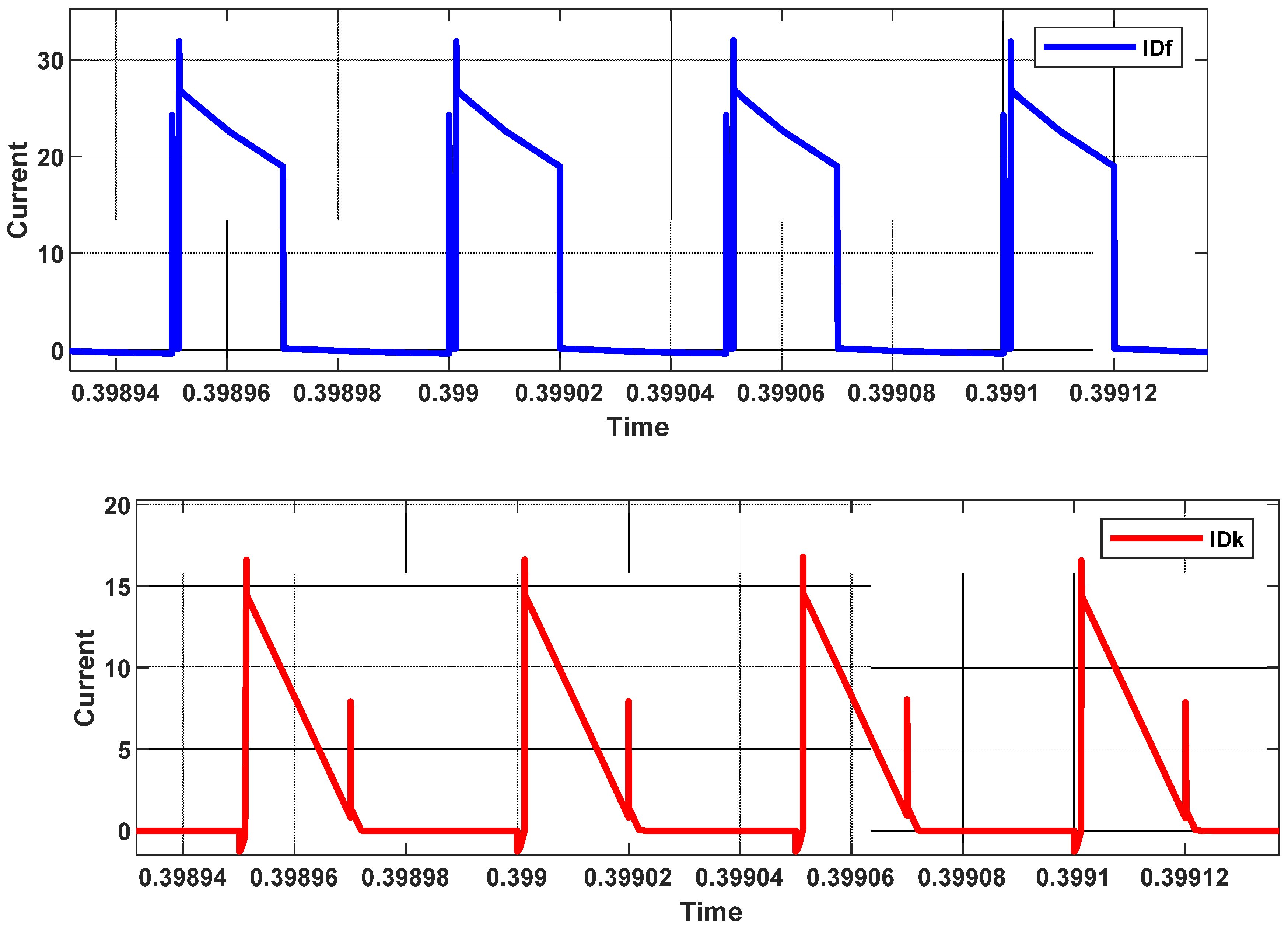
3.2. Results and Waveforms

In this subsection, the simulation results are discussed thoroughly. Figure 6 displays the output voltages. It can be seen that the average output voltage of the HFC converter is 50 V DC (green). Additionally, the 50 V load voltage is the sum of the flyback (blue) and the Cuk (red) voltages. The energy is transferred from the input to the output through the flyback capacitor. Moreover, the output energy stored in the Cuk capacitor can be used to simultaneously charge a storage element, such as a battery. This is the dual operation capability of the proposed topology that makes it especially useful for novel power system applications.
Figure 7 shows the Lm and Lk currents for both inductances in CCM. The voltage and current of the switch Q are shown in Figure 8. During switch voltage fall time (red color), the switch output capacitance is forced to discharge its energy through the switch channel; then, the switch voltage is rapidly decreased to zero. The speed of discharging the energy depends on the switch current, known as hard switching [25]. This also can happen for switch voltage rise time, when the output capacitor charges and the voltage is rapidly increased to Vin (high). The hard switching of the switch Q affects the rising and falling edges of the drain current, so abrupt changes in the drain current are seen.
The following suggestions can solve this issue: An extra capacitance could be connected in parallel with drain–source capacitance. This results in zero voltage switching.
The second solution could be changing the operating mode from continuous (CCM) to discontinuous current mode (DCM) or CRitical conduction mode (CRM). Operating the system under one of those two modes can investigate zero current switching.
In addition, the diode currents of the flyback and Cuk converters are displayed in Figure 9. As seen in Figure 9, both diodes are conducted under hard switching conditions. Thus, the diode currents show overcurrent in their waveforms [25].

3.3. Efficiency Assessment

Because the proposed HFC converter uses only one controlled switch instead of two, its efficiency is enhanced compared to the efficiency of each individual converter. Therefore, the number of components for the proposed HFC converter is reduced. The efficiency of the converter can be calculated as:
η = P o P o + P l o s s
where Po is the output power of the converter and Ploss is the total losses in all converter components. The losses in the converter can be divided into three main components: conduction losses, switching losses and control losses [26,27]. Table 2 summarizes the loss calculations, and the efficiency of the HFC converter is compared with the efficiency of Figure 1. This is shown in Figure 10. Table 3 compares the number of components between HFC topology and the conventional flyback and Cuk topology.

3.4. Effect of Load Change

The efficiency of HFC is plotted as a function of the load current in Figure 11, which also maintains a constant input/output voltage of 220/50 V. The loading was raised, which led to an increase in efficiency. The HFC has an efficiency of approximately 90 percent when it is operating under full load circumstances.

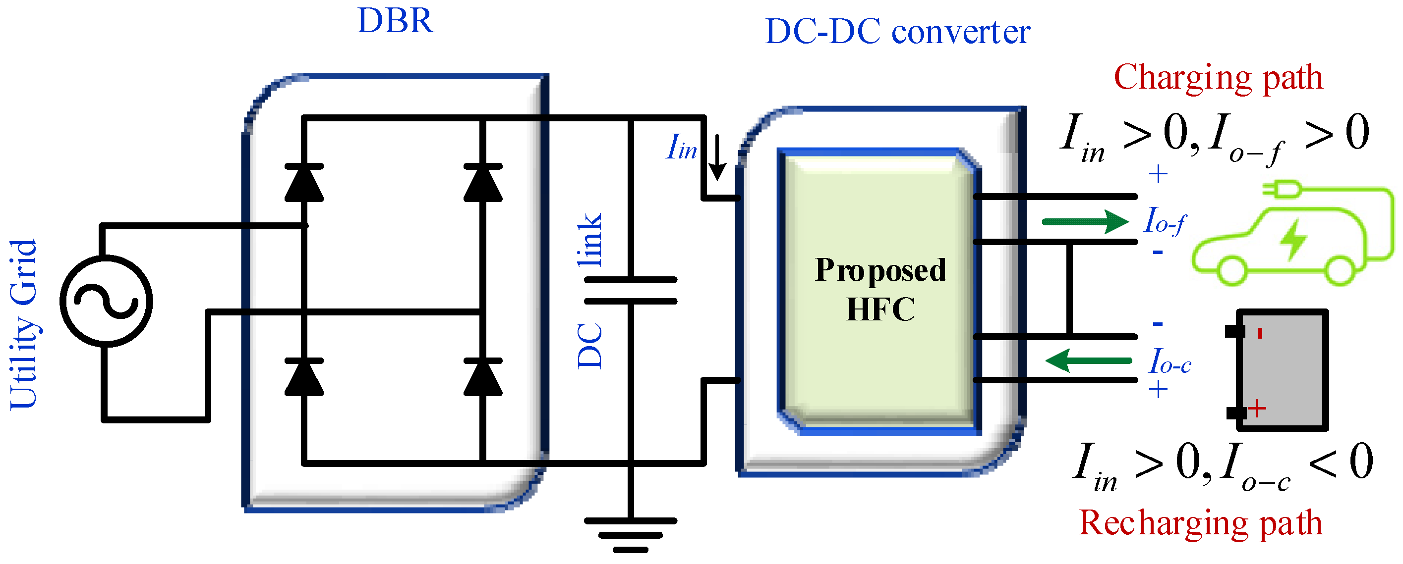
4. Application: Electric Vehicle Adapter

Countries all over the world are keen to replace internal combustion engine vehicles with new electric vehicles (EVs) to alleviate the resource crisis and reduce greenhouse gas (GHG) emissions [28]. EVs can also interact with the smart grid [29] and be used to support power system stability [30,31] and help increase renewable energy penetration [32,33]. Thus, since EVs are becoming increasingly popular in the current research field, there is a need to develop a circuit and converter for charging these EVs using the excess electricity provided by the grid. The vast majority of electric vehicles use DC power, so DC-DC converters are required to connect them to the grid. In industrial applications, various types of converters are employed for different purposes, including EV charging. The most common are buck and boost converters. Two switch forward converters are primarily used to convert DC to DC, allowing these converters to be used in electric vehicles. The main purpose of utilizing these converters is that they increase the system’s efficiency while also making it more economical for commercial and industrial use. However, as detailed by [34], these types of converters have some drawbacks. To overcome the drawbacks of traditional DC-DC converters, researchers investigated numerous methods for increasing the efficiency of EV chargers and charging systems. In [35], for example, a new switched capacitor DC-DC converter design for electric vehicle applications is proposed. To charge the EV, the proposed topology [34] can function as a bidirectional power converter, which means that in this instance, the output section is an active stage capable of providing power, similar to how a low-voltage battery or a supercapacitor would. A hybrid EV charger was also made with a DC-DC converter that works both ways, from the grid to the vehicle and from the vehicle to the grid [36]. The main feature of this converter is that it can operate at a wide range of high voltage gains. However, these topologies have high switching losses because they consist of more than a switch, a single input, a single output, and a low range of duty cycles.
The HFC can overcome these drawbacks for more efficient EV and renewable energy applications. It can also operate in either step-down or step-up mode, with a high gain between the output and input voltage in both circumstances. A case study of EV adapters (chargers) to test the HFC capability is linked to its terminal. The structure of the EV adapter-connected HFC to charge the EV from the power grid, as shown in Figure 12. The universal AC input voltage comes from the grid. Then it is rectified using a diode bridge rectifier (DBR). A low-pass DC link capacitor filters the rectified voltage to eliminate the effect of high-frequency harmonics in the grid voltage. A DC-DC converter chops the rectified voltage to boost up or buck down the voltage based on the sufficient EV level. This case study investigates the use of the proposed HFC as an EV charger. As mentioned before, the proposed HFC can:
1.
Forward the energy when Iin > 0 and Io_f > 0. This means the load consumed the power from the proposed converter’s upper terminals (flyback terminals).
2.
Reverse the energy when Iin > 0 and Io_c < 0. This means the energy storage system is being charged from the proposed converter’s lower terminals (Cuk terminals).
A constant power of 1.5 kW, 20 kHz EV charger is simulated over the universal grid voltage (110 Vrms–260 Vrms).
Figure 13 and Figure 14 show the waveforms when the RMS input voltage is 220 V and 110 V, respectively. The line current (Figure 13A) is filtered using a low pass filter. The rectified voltage is shown in Figure 13B. The forward and reverse output voltages of the proposed HFC are also shown in Figure 13C,E. In addition, the suggested HFC currents are depicted in Figure 13D,F, respectively. While the forward current is responsible for supplying the energy, the reverse current is what is responsible for recharging the energy storage system.
The same is applied to Figure 14. It can be seen that; the voltage and current instability are related to the optimal filter design parameters. When the results at two different line voltages are taken for the same capacitance value used in the simulation, this value can be changed to get more stable signals with minimum ripple percentage values. At low line voltage (110 Vrms), after 0.05 s, the voltage and current were settled down and became more stable. Additionally, the ripple percentage for reverse voltage and current is within the standard limits.
The total harmonics distortion (THD) must meet the standards. This can be measured by fast fourier transform (FFT) tools in MATLAB. Figure 15A,B display the harmonics content of the AC input current in both cases of input voltages. When the AC input voltage is 110 Vrms, the current has higher THD than the AC input current when the input voltage is 220 Vrms. Furthermore, the odd harmonics are noticeable in both AC input currents, especially third and fifth harmonics. A proper input filter design must be considered to reduce the THD in both currents further.
In addition, the power factor (PF) of the line current must be calculated based on the simulated THD, which is given by (assuming the displacement factor is 1):
P F = 1 1 + ( T H D 2 )        
According to Equation (16), the power factor of the input current is plotted in Figure 16 over the universal range of the input voltage. The PF of the input current is 96.6% (when Vin is 220 Vrms), whereas the PF of the input current is 94.01% (when Vin is 110 Vrms). Both power factors are within an acceptable limit.

5. Conclusions

This paper proposes a new hybrid flyback-Cuk (HFC) converter. The developed HFC converter’s detailed analysis, design, and derivations are discussed. The proposed HFC converter is more efficient than each converter separately because it only has one control switch instead of two. Therefore, the number of parts needed for the proposed HFC converter is cut down. The results show that HFC has characteristics that make it much better than using a single flyback or Cuk converter. HFC enhances the voltage gain over a wide range of duty cycles. It provides the step-down capability and keeps the voltage gain below 1 at higher duty cycles, such as around 82%. The efficiency of HFC reaches about 90% at these high duty cycles. It can also supply and receive energy simultaneously. HFC’s new topology converter could be applicable for many applications, such as energy conversion systems, due to its new features as compared to conventional converters. A 1.5 kW case study of an electric vehicle is simulated to show the effectiveness of the proposed converter.

Author Contributions

Conceptualization, K.A.M.; methodology, K.A.M. and M.A.O.; software, K.A.M.; validation, M.A.O., A.Q.A.-S. and T.S.U.; formal analysis, K.A.M., M.A.O., A.Q.A.-S. and T.S.U.; investigation, A.Q.A.-S. and T.S.U.; writing—original draft preparation, K.A.M., M.A.O., A.Q.A.-S. and T.S.U.; writing—review and editing, K.A.M., M.A.O., A.Q.A.-S. and T.S.U.; project administration, T.S.U. All authors have read and agreed to the published version of the manuscript.

Funding

This research received no external funding.

Data Availability Statement

Not applicable.

Conflicts of Interest

The authors declare no conflict of interest.

References

  1. Bhaskar, M.S.; Padmanaban, S.; Almakhles, D.J.; Gupta, N.; Subramaniam, U. Double-switch switched-inductor converter with minimal switch voltage stress for renewable energy conversion. Comput. Electr. Eng. 2022, 98, 107682. [Google Scholar] [CrossRef]
  2. Obeidat, M.A.; Hamad, A. Applying Two Controller Schemes to Improve Input Tracking and Noise Reduction in DC-DC Converters. Przegląd Elektrotech. 2019, 95, 105. [Google Scholar] [CrossRef]
  3. Bottion, A.J.B.; Barbi, I. Input-Series and Output-Series Connected Modular Output Capacitor Full-Bridge PWM DC–DC Converter. IEEE Trans. Ind. Electron. 2015, 62, 6213–6221. [Google Scholar] [CrossRef]
  4. Marzang, V.; Tabbat, P.A.; Khoshkbar-Sadigh, A.; Mohseni, P.; Hashemzadeh, S.M.; Talebian, I. An Interleaved High Step-Up DC-DC Converter with Low Voltage-Stress on Semiconductors. In Proceedings of the IECON 2020 The 46th Annual Conference of the IEEE Industrial Electronics Society, Singapore, 18–21 October 2020; pp. 1223–1228. [Google Scholar] [CrossRef]
  5. Outeiro, M.T.; Visintini, R.; Buja, G. Considerations in Designing Power Supplies for Particle Accelerators. In Proceedings of the IECON 2013-39th Annual Conference of the IEEE Industrial Electronics Society, Vienna, Austria, 10–13 November 2013; pp. 7076–7081. [Google Scholar]
  6. Richelli, A.; Salem, M.; Colalongo, L. A Review of Fully Integrated and Embedded Power Converters for IoT. Energies 2021, 14, 5419. [Google Scholar] [CrossRef]
  7. Zhang, N.; Sutanto, D.; Muttaqi, K.M. A review of topologies of three-port DC-DC converters for the integration of renewable energy and energy storage system. Renew. Sustain. Energy Rev. 2016, 56, 388–401. [Google Scholar] [CrossRef]
  8. Kushwaha, R.; Singh, B. A Power Quality Improved EV Charger With Bridgeless Cuk Converter. IEEE Trans. Ind. Appl. 2019, 55, 5190–5203. [Google Scholar] [CrossRef]
  9. Pires, V.F.; Cordeiro, A.; Foito, D.; Silva, J.F. High Step-Up DC–DC Converter for Fuel Cell Vehicles Based on Merged Quadratic Boost–Ćuk. IEEE Trans. Veh. Technol. 2019, 68, 7521–7530. [Google Scholar] [CrossRef]
  10. Ananthapadmanabha, B.R.; Maurya, R.; Arya, S.R. Improved Power Quality Switched Inductor Cuk Converter for Battery Charging Applications. IEEE Trans. Power Electron. 2018, 33, 9412–9423. [Google Scholar] [CrossRef]
  11. Dong, H.; Xie, X.; Zhang, L. A New CCM/DCM Hybrid-Mode Synchronous Rectification Flyback Converter. IEEE Trans. Ind. Electron. 2020, 67, 3629–3639. [Google Scholar] [CrossRef]
  12. Pesce, C.; Blasco, R.; Riedemann, J.; Andrade, I.; Peña, R. A DC-DC Converter Based On Modified Flyback Converter Topology. IEEE Lat. Am. Trans. 2016, 14, 3949–3956. [Google Scholar] [CrossRef]
  13. Tamyurek, B.; Kirimer, B. An Interleaved High-Power Flyback Inverter for Photovoltaic Applications. IEEE Trans. Power Electron. 2015, 30, 3228–3241. [Google Scholar] [CrossRef]
  14. Marjani, J.; Imani, A.; Hekmati, A.; Afjei, E. A new dual output DC-DC converter based on SEPIC and Cuk converters. In Proceedings of the 2016 International Symposium on Power Electronics, Electrical Drives, Automation and Motion (SPEEDAM), Capri, Italy, 22–24 June 2016; pp. 946–950. [Google Scholar] [CrossRef]
  15. Banaei, M.R.; Hossein, A.; Alizadeh, R.; Farakhor, A. Non-isolated multi-input–single-output DC/DC converter for photovoltaic power generation systems. IET Power Electron. 2014, 7, 2806–2816. [Google Scholar] [CrossRef]
  16. Lodh, T.; Majumder, T. A high gain high-efficiency negative output flyback-Cuk integrated DC-DC converter. In Proceedings of the 2016 International Conference on Signal Processing, Communication, Power and Embedded System (SCOPES), Paralakhemundi, India, 3–5 October 2016; pp. 63–68. [Google Scholar] [CrossRef]
  17. Tseng, S.-Y.; Fan, J.-H. Buck-boost/flyback hybrid converter for solar power system applications. Electronics 2021, 10, 414. [Google Scholar] [CrossRef]
  18. Da Costa, A.E.L.; Andersen, R.L. In High-gain boost-boost-flyback converter for renewable energy sources applications. Proceeding of the 2015 IEEE 13th Brazilian Power Electronics Conference and 1st Southern Power Electronics Conference (COBEP/SPEC), Fortaleza, Brazil, 29 November 2015; pp. 1–6. [Google Scholar]
  19. Zhang, F.; Xie, Y.; Hu, Y.; Chen, G.; Wang, X. A hybrid boost–flyback/flyback microinverter for photovoltaic applications. IEEE Trans. Ind. Electron. 2019, 67, 308–318. [Google Scholar] [CrossRef]
  20. Shitole, A.B.; Sathyan, S.; Suryawanshi, H.; Talapur, G.G.; Chaturvedi, P. Soft-switched high voltage gain boost-integrated flyback converter interfaced single-phase grid-tied inverter for spv integration. IEEE Trans. Ind. Appl. 2017, 54, 482–493. [Google Scholar] [CrossRef]
  21. Alatai, S.; Salem, M.; Ishak, D.; Das, H.S.; Alhuyi Nazari, M.; Bughneda, A.; Kamarol, M. A Review on State-of-the-Art Power Converters: Bidirectional, Resonant, Multilevel Converters and Their Derivatives. Appl. Sci. 2021, 11, 10172. [Google Scholar] [CrossRef]
  22. Zhang, F.; Yan, Y. Novel Forward-Flyback Hybrid Bidirectional DC-DC Converter. IEEE Trans. Ind. Electron. 2009, 5, 1578–1584. [Google Scholar] [CrossRef]
  23. Chiu, H.-J.; Lo, Y.-K.; Lee, H.-C.; Cheng, S.-J.; Yan, Y.-C.; Lin, C.-Y.; Wang, T.-H.; Mou, S.C. A Single-Stage Soft- Switching Flyback Converter for Power-Factor-Correction Application. IEEE Trans. Ind. Electron. 2010, 57, 2187–2190. [Google Scholar] [CrossRef]
  24. Anand, A.; Singh, B. Modified Dual Output Cuk Converter-Fed Switched Reluctance Motor Drive with Power Factor Correction. IEEE Trans. Power Electron. 2019, 34, 1. [Google Scholar] [CrossRef]
  25. Mahafzah, K.; Krischan, K.; Muetze, A. Efficiency Enhancement of a Three Phase Hard Switching Inverter Under Light Load Conditions. In Proceedings of the IECON 2016, Florence, Italy, 23–26 October 2016. [Google Scholar]
  26. Orabi, M.; Shawky, A. Proposed Switching Losses Model for Integrated Point-of-Load Synchronous Buck Converters. IEEE Trans. Power Electron. 2015, 30, 9. [Google Scholar] [CrossRef]
  27. Glitz, E.S.; Ordonez, M. MOSFET Power Loss Estimation in LLC Resonant Converters: Time Interval Analysis. IEEE Trans. Power Electron. 2019, 34, 12. [Google Scholar] [CrossRef]
  28. Begwani, A.K.; Ustun, T.S. Electric bus migration in Bengaluru with dynamic charging technologies. AIMS Energy 2017, 5, 944–959. [Google Scholar] [CrossRef]
  29. Ustun, T.S.; Zayegh, A.; Ozansoy, C. Electric vehicle potential in Australia: Its impact on smartgrids. IEEE Ind. Electron. Mag. 2013, 7, 15–25. [Google Scholar] [CrossRef]
  30. Hussain, S.M.S.; Aftab, M.A.; Ali, I.; Ustun, T.S. IEC 61850 based energy management system using plug-in electric vehicles and distributed generators during emergencies. Int. J. Electr. Power Energy Syst. 2020, 119, 105873. [Google Scholar] [CrossRef]
  31. Ustun, T.S.; Hussain, S.M.S.; Syed, M.H.; Dambrauskas, P. IEC-61850-Based Communication for Integrated EV Management in Power Systems with Renewable Penetration. Energies 2021, 14, 2493. [Google Scholar] [CrossRef]
  32. Aftab, M.A.; Hussain, S.M.S.; Ali, I.; Ustun, T.S. IEC 61850 and XMPP Communication Based Energy Management in Microgrids Considering Electric Vehicles. IEEE Access 2018, 6, 35657–35668. [Google Scholar] [CrossRef]
  33. Ustun, T.S.; Hussain, S.M.S.; Kikusato, H. IEC 61850-Based Communication Modeling of EV Charge-Discharge Management for Maximum PV Generation. IEEE Access 2019, 7, 4219–4231. [Google Scholar] [CrossRef]
  34. Chakraborty, S.; Vu, H.-N.; Hasan, M.M.; Tran, D.-D.; Baghdadi, M.E.; Hegazy, O. Dc-dc converter topologies for electric vehicles, plug-in hybrid electric vehicles and fast charging stations: State of the art and future trends. Energies 2019, 12, 1569. [Google Scholar] [CrossRef]
  35. Pellitteri, F.; Di Dio, V.; Puccio, C.; Miceli, R. A model of dc-dc converter with switched-capacitor structure for electric vehicle applications. Energies 2022, 15, 1224. [Google Scholar] [CrossRef]
  36. Heydari-doostabad, H.; O’Donnell, T. A wide-range high-voltage-gain bidirectional dc–dc converter for v2g and g2v hybrid ev charger. IEEE Trans. Ind. Electron. 2021, 69, 4718–4729. [Google Scholar] [CrossRef]
Figure 1. The conventional use of flyback and Cuk converters.
Batteries 08 00093 g001
Figure 2. (a) The proposed HFC converter with the voltage control loop, (b) key waveforms.
Batteries 08 00093 g002
Figure 3. The proposed HFC converter (switch Q is ON).
Batteries 08 00093 g003
Figure 4. The proposed HFC converter (switch Q is OFF).
Batteries 08 00093 g004
Figure 5. The voltage gains of three converters for different duty cycles.
Batteries 08 00093 g005
Figure 6. Output voltages, flyback voltage (blue), Cuk voltage (red), and HFC voltage (green).
Batteries 08 00093 g006
Figure 7. Lm and Lk currents in CCM of HFC converter.
Batteries 08 00093 g007
Figure 8. The switch voltage (red) and drain current (green) of the HFC converter.
Batteries 08 00093 g008
Figure 9. The diode currents in the proposed HFC converter, IDf (blue), and IDk (red).
Batteries 08 00093 g009
Figure 10. The efficiency comparison over duty cycle variation.
Batteries 08 00093 g010
Figure 11. HFC converter efficiency under different load conditions.
Batteries 08 00093 g011
Figure 12. Structure of the EV adapter-connected HFC.
Batteries 08 00093 g012
Figure 13. Waveforms when the input voltage is 220 Vrms. (A) line current, (B) rectified voltage (C) forward voltage, (D) forward current, (E) reverse voltage, (F) reverse current.
Batteries 08 00093 g013aBatteries 08 00093 g013b
Figure 14. Waveforms when the input voltage is 110 Vrms. (A) line current, (B) rectified voltage (C) forward voltage, (D) forward current, (E) reverse voltage, (F) reverse current.
Batteries 08 00093 g014
Figure 15. THDs when the input voltage is (A). 110 Vrms, (B). 220 Vrms.
Batteries 08 00093 g015
Figure 16. Power factor of the line input current over the universal voltage range.
Batteries 08 00093 g016
Table 1. The selected parameters for the simulation.
ParameterDescriptionValue
Pin/Poinput/output power300 W
Vininput voltage220 V
Vooutput voltage50 V
Iooutput current6 A
Roload resistance8.3 Ω
fsswitching frequency20 kHz
Lmmagnetization inductance18 mH
Np/Nstransformer T turns ratio220/90
Cfflyback output capacitance0.2 mF
CkCuk coupling capacitance110 uF
LkCuk second inductance34 uH
CckCuk output capacitance20 nF
Table 2. Calculation of loss components [25,26,27].
Losses TypeEquationConditions
Losses of Figure 2
conduction lossIn Q P c o n Q = R o n V i n 2 3 D R 1 2 Ron: MOSFET on-state resistance
R1: series resistance of the current loop
In Df or Dk P c o n D f = V f V i n 2 4 V o R 1 Vf: flyback diode forward voltage
switching lossIn Q P s w Q = 0.5 f s C o s s ( 0.5 V i n + V o ) 2 Coss: switch output capacitance
In Df or Dk P s w Q = 0.5 f s C d ( 0.5 V i n + V o ) 2 Cd: diode parasitic capacitance
control loss P g Q = 2 Q g V g f s Qg: switch gate charge
Vg: voltage needed to charge the gate
transformer lossCopper losses are considered with conduction losses.
Core losses are ignored because it is assumed that the core is ideal.
total loss P t = P c o n d Q + P c o n d D f + P c o n d D k + P s w Q + P g Q
Table 3. Summary of different comparison aspects between HFC and a conventional system.
Comparison AspectThe Proposed HFC as Shown
in Figure 2
Conventional Circuit of
Flyback and Cuk Converters
number of transformers11
number of passive components45
number of diodes22
number of switches12
number of control loops12
number of power supplies12
number of output ports32
voltage stress across Q V i n + N p N s V f V i n + N p N s V f
step down capabilityable to step down Vo when DQ < 85%able to step down Vo when DQ < 50%
voltage gain (VG)lower VG over DQhigher VG over DQ
efficiency at full load conditions89%88.3%
Publisher’s Note: MDPI stays neutral with regard to jurisdictional claims in published maps and institutional affiliations.

