Abstract
In this article, the performance of brass electrode was investigated in a Zn-air (charcoal-based cathode) rechargeable battery. The construction of the battery was carried out with biodegradable materials, namely a cotton cloth diaphragm and carboxymethyl cellulose sodium salt (CMC-Na) viscosity modifier, while the battery skeleton was printed by 3D printing technology. The brass acted as a collector and a preferable surface for the metallic Zn deposition on the brass anode surface. The electrochemical behavior of the brass anode was investigated by cyclic voltammetry (CV). Cyclic performance tests were carried out, which showed stable cell operation even in the presence or absence of additives up to more than 100 cycles. Furthermore, high energy (Eeff) and Coulomb (Ceff) efficiencies, 80% (Eeff), 95% (Ceff), 75% (Eeff), and 95% (Ceff) were obtained, respectively. The Shepherd model was applied to describe the discharging processes of the Zn-air battery containing brass as anode in the presence of additive-free electrolyte or electrolyte with CMC-Na salt additive. It was found that the Shepherd equation described only approximately the resulting discharge curves. In order to attain a more precise mathematical description, stretched exponential function was implemented into the last term of the Shepherd equation. The need for such a correction shows the complexity of the electrochemical processes occurring in these systems. In addition, the surface of the brass anode was also investigated by scanning electron microscopy (SEM) and the composition of the brass alloys was determined by X-ray fluorescence spectroscopy (XRF). Importantly, the formation of dendritic deposition was successfully suppressed and a smooth and uniform surface was obtained after the cycling tests.
1. Introduction
In the last decades, batteries (such as metal-air batteries), supercapacitors, and other hybrid systems (with battery + supercapacitor properties) have taken on new importance in aspirations of making green and high-performance energy storage and utilization [1,2]. For this reason, several metal-air batteries such as lithium-air [3,4], aluminum-air [5] and zinc-air [6,7] have been preferred for having a long life, being cheaper, and being more stable batteries over the conventional lithium-ion batteries, which have insufficient energy density, low capacity, and safety issues [8,9]. To improve the structural stability and the electrochemical performance of the batteries, development of the electrode materials (e.g., based on Ni-Co, graphene, or MXene) [10,11] and modifications of the electrolyte composition are the focus of research [12]. Among the metal-air batteries, due to their high energy densities (up to 1350 Wh/kg) and safety operation [13,14], rechargeable zinc-air batteries have been in the focus of research interest. However, despite their high energy densities, the zinc-air batteries have some disadvantages including the lack of the morphology control of zinc deposition during the charging process (minimizing the dendrite formation) [15,16,17] and providing suitable catalyst(s) for the oxygen evolution/reduction reactions (OER/ORR) [18,19,20,21]. The inhibition of the dendritic deposition can be promoted by varying the composition of the electrolyte; this means the application of additives that can act as a surfactant and/or chelating agent [16,22,23,24]. The other possibility is to find an optimal operating condition that usually means the application of an appropriate (not too high) current density for charging [25,26]. In addition to these solutions, it should be mentioned the morphology of the surface of the zinc anode that can also affect the dendrite formation [27].
Recently, we reported our novel zinc-air cell that is heavy metal free with fixed cell geometry and showed promising cell operation without deposit formation on the zinc anode. Our cell was tested with some additives (such as carboxyl telechelic poly(ethylene glycol) and carboxymethyl cellulose sodium salt (CMC-Na)), and fixed geometry was ensured by a 3D printer [22,28].
For further studies of our prototype cell and to get a deeper insight into the possibilities of the utilization of our cell, the zinc anode was replaced by copper-zinc alloy (brass). The brass is widely used as a current collector in the electrochemical cells [29] and several metal-copper alloys including aluminum-copper [30], silver-copper [31], or tin-copper [32] were applied as anode in different batteries. However, no metal-air battery was found in the literature where brass acted as an anode although brass is commercially available and has very good electrical conductivity.
In this paper, we focused our studies on a modified zinc-air battery using brass as an anode and graphite/charcoal (immersed in concentrated KOH solution saturated with K2[(Zn(OH)4)] electrolyte) as a cathode. We will show that this new cell can work as a zinc-air battery with excellent energy efficiency. Furthermore, the cell is heavy metal free and printed by a 3D printer using polypropylene filament to ensure the fixed geometry.
2. Experimental
2.1. Materials
Brass foil (CuZn37, thickness: 0.63 mm, EN 1652, DIN17660) was purchased from TGF Ltd. (Debrecen, Hungary). Graphite rod electrodes originated from Ceramics Praha (Czech Republic, Prague). All the electrodes were rinsed with n-hexane and then allowed to air-dry prior to analysis. Charcoal, potassium hydroxide, n-hexane, and zinc oxide were obtained from VWR (Debrecen, Hungary). The carboxymethyl cellulose (CMC) Na salt was purchased from Merck (Darmstadt, Germany).
2.2. XRF Characterization of the Brass
In order to create an applicable anode, commercially available, cheap materials are preferable as the applied brass. The composition of the brass anode was determined by X-ray fluorescent measurements and the following elements were involved in the analysis: Fe, Co, Ni, V, Cr, Zr, Nb, Mo, Pd, Ag, Cd, Sn, Sb, Hf, Ta, W, Re, Pb, and Bi. The results showed the presence of Cu: 63.19%, Zn: 36.48% Fe: 0.07%, Ni: 0.07%, and Sn: 0.06% in m/m%. The threshold was 0.05 m/m%.
In the brass, low Fe, Ni, and Sn content were determined in addition to the Cu and Zn; however, Pb was not observed, even though the EN 1652, DIN17660 standards allow its presence in a small portion.
2.3. Electrodes
The air cathode was constructed from charcoal and a graphite rod. The charcoal was soaked for 8 h in the electrolyte to obtain the mud before use. The brass anode was cut from the brass foil (length 10 cm, width 10 mm) and fixed to the PP skeleton keeping a constant distance (1.5 mm) between the brass anode and the cotton diaphragm. The detailed cell geometry was published earlier [28].
2.4. Potentiostat
For the cyclic voltammetry (CV) measurements and cyclic performance tests, a Biologic SP-150 potentiostat (Seyssinet-Pariset, France) was applied, equipped with the EC-Lab software package. The CV measurements were recorded in the range of −0.1 V to −1.85 V vs. cell potential with the scan speed of 20 mV/s. In the case of cycling performance tests, the working potential range was set from 1.0 V to 1.8 V. The charging and discharging current density was 2 mAcm−2. The energy efficiencies were calculated from the area under the charge/discharge profiles.
2.5. Scanning Electron Microscopy (SEM)
The surface of the anodes was investigated by a Hitachi S-4300 scanning electron microscope (Tokyo, Japan). The samples were stored in n-hexane until the analysis.
2.6. The 3D-Printed Battery and the Electrolytes
The skeleton of the battery cell was printed from polypropylene (Fiberlogy) using a Prusa i3 MK3S 3D printer. (Czech Republic, Prague). The anode was fixed to the battery skeleton, and the distance between the anode and membrane was 1.5 mm. The size of the anode was 100 × 10 × 0.8 mm, (length, width, and thickness). The cotton cloth membrane was soaked in lye for 1 h before filling the charcoal-based cathode. For the preparation of the cathode, mud was made by mixing 6 M aqueous potassium hydroxide containing 0.25 M K2[(Zn(OH)4)] (with or without additive) with charcoal (soaked for 8 h). The CMC-Na salt additive was applied at a concentration of 2 m/v%. As the last step of the battery preparation, the graphite rod was placed in the middle of the mud and kept in position with 3D-printed arms. The exploded-view of the 3D-printed cell is shown in the Supporting Information (Figure S1).
3. Results and Discussion
3.1. Cyclic Voltammetry
Our aim was to investigate the applicability of the bimetallic Cu-Zn alloy as Zn anode in a Zn-air battery. The results (Coulomb and energy efficiencies, cycling test, cyclic voltammetry) obtained for the zinc-air battery using zinc as anode and same cell geometry can be found in our previous publication [28]. The electrochemical reactions were investigated by cyclic voltammetry measurements with different electrolytes (with or without CMC-Na salt additive). One hour prior to analysis, the electrodes were inserted into the corresponding electrolytes. The potential range was set to be −0.1 V to −1.85 V. In this way, the reduction/oxidation of all copper and zinc species was recognized. Figure 1 shows the recorded cyclic voltammograms in the presence or absence of additives.
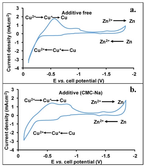
Figure 1.
Cyclic voltammograms recorded in the absence (a) or presence of CMC-Na salt additive (b), applying brass anode. The KOH and K2[(Zn(OH)4)] concentrations in the electrolytes were 6.0 M and 0.25 M, respectively.
As seen in Figure 1a,b, the voltammograms with the use of brass anodes are complex since within the investigated potential range the reduction-oxidation of copper and related species also takes place. The potential range from −0.3 V up to −1 V corresponds to the reduction of copper (Cu(II) to Cu(0), gross) [33,34]. Due to the formed passive layer on the surface of the brass electrode, both Cu(II) and Cu(I) are present. At higher potential, the Cu(II) is reduced to Cu(I) species, while around −1 V Cu(0) is formed. The broad CV peaks observed are, most likely, due to the overlapping peaks. Interestingly, applying the CMC-Na salt as an additive a positive shift can be found for the reduction of Cu(I) species.
Decreasing the potential, at −1.1 V, the Zn deposition starts to take place, whereas the peak maxima are around −1.45 V. Moreover, an increase in the current at higher cell potential may be the result of further Zn deposition. The electrolysis of water starts only at a lower cell potential; bubbles were not formed during the analysis. The height of these peaks is lower than those obtained by the transition of copper-related compounds, which may be the result of the higher surface concentration of copper species with respect to those of Zn. The formation of CuO, Cu(OH)2, and Cu2O starts at −0.7 V. Based on the cyclic voltammograms, the voltage span from −1 V to −1.8 V was selected as a working cell potential range for the cyclic test of the battery.
3.2. Cycling Test of the Zn-Air Battery
The cell potential of the Zn-air battery using brass as an anode was found to be around −0.39 V. This originates from the passivation of the copper under alkaline conditions, where a double Cu2O/Cu(OH)2 layer is formed [35]. The cyclic performance test of the Zn-air secondary battery was run in the absence or presence of CMC-Na salt additives (Mn: 250 kg/mol, f: 1.2) and 2 mAcm−2 was applied as a charging-discharging current density. The time limit of the charging and discharging processes was set to be 5-5 min (one full cycle was 10 min), except for the first step, when the brass surface was preconditioned (a full cycle was 20 min). The potential limits were set to be 1.8 V and 1.0 V as the maximum and minimum values, respectively.
First, the battery filled with additive-free electrolyte was investigated, which showed excellent performance (Figure 2). The working potentials varied from 1.0 V to 1.45 V. The relatively low potential can be explained by the involvement of a two-electron mechanism (the peroxide pathway) taking place on the charcoal-based cathode as detailed in our previous work [28]. Every time, the battery reached 1.0 V limit during the discharging process and stable performance was observed up to more than 100 cycles. In Figure 2a,b, the cyclic performance test and the zoomed cycles are shown in the time interval of 10.05–10.45 h, respectively. Similar shapes were observed for all the cycles. The shape of the curves will be detailed later. It is also clearly seen that the charging potential was reached at 1.33 V; after that, only a very small increase in the potential was observed within the cycle. During the discharge, stable cell potential was obtained until 1.15 V. After that period, a sharp decrease in the cell potential was observed (for instance, in Figure 2b, from 10.25 min shown red frame) indicating the depletion of zinc from the outer layers of the brass anode. Such a decrease was not seen in the case of the metal Zn anode [28]. The small difference between the charging and discharging potentials indicates a low overpotential, which results in high energy efficiency for the battery. The energy efficiency was 80% while the Coulomb efficiency was higher than 92%. The efficiencies versus cycle numbers are presented in Figure 3.
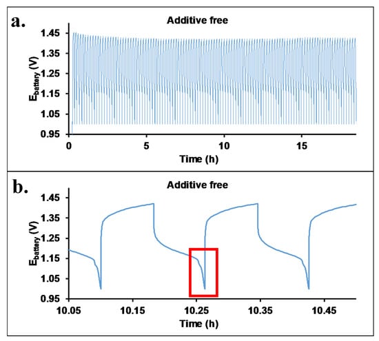
Figure 2.
The cyclic performance test (a) of the Zn-air battery filled with additive-free electrolyte, aqueous KOH (6 M) and K2[(Zn(OH)4)] (0.25 M). The lower figure (b) shows the zoomed charging/discharging cycles (the sharp decreasing in the cell potential is highlighted by red frame).

Figure 3.
The energy (a) and Coulomb efficiency (b) of the Zn-air battery equipped with brass anode with additive-free electrolyte, aqueous KOH (6 M) and K2[(Zn(OH)4)] (0.25 M).
One of the main shortcomings of KOH electrolytes in batteries is the evaporation of water, which brings about a change in the concentration of the KOH and K2[(Zn(OH)4)] during operation. The rate of evaporation may be decreased by the increase in the viscosity of the electrolyte. Therefore, carboxymethyl cellulose-Na salt (CMC-Na) was used as a viscosity improver. Recently, we have shown that CMC-Na salt with 250 kg/mol molecular weight and 1.2 functionality results in a high increase in viscosity (75 mPas vs. 1.5 mPas additive free) [28], with a small increase in the battery working potential range. Figure 4 shows the cycling performance test of the Zn-air battery filled with an electrolyte containing CMC-Na salt. Similar to the additive-free electrolyte, excellent performance was also obtained. The maximum of the working potential range increased up to 1.52 V. High energy efficiency (Eeff: 75%) and Coulomb efficiency (Ceff: 92%) were determined similar to that of the additive-free cell (80%). The small decrease in the energy efficiency values may originate from the increased electric resistance of the electrolyte containing CMC-Na salt. Comparing our results with energy efficiency values (60–75%) found in the literature [36,37,38], it can be surmised that the values obtained for our cells are outstanding. The energy efficiency and Coulomb efficiency as a function of cycle numbers are shown in Figure 5.
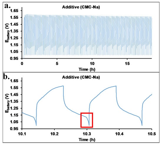
Figure 4.
The cyclic performance test (a) of the Zn-air battery filled with an electrolyte containing 2 m/v% CMC-Na salt. The lower figure (b) shows the zoomed charging/discharging cycles (the sharp decreasing in the cell potential is highlighted by red frame).

Figure 5.
The energy (a) and Coulomb efficiency (b) of the Zn-air battery equipped with brass anode with 2 m/v% CMC-Na salt additive, aqueous KOH (6 M), and ZnO (0.25 M).
In order to characterize the electrochemical processes taking place in the battery, it should be taken into account that during the production of a brass sheet, different defects might form. The presence of these defects on the surface may originate from the bimetallic crystal lattice and/or the mechanical stress during the fabrication. To explain our data, i.e., the detected relatively small differences between the charging and discharging potentials, we should take into account that in the presence of electrolyte of eider type applied, these defects decrease the Volta potential and thus, reduce the overpotential of the anodic oxidation of the Zn metal [39]. The lower the overpotential is the higher is the energy efficiency.
3.3. Mathematical Modeling of Discharging Processes
As it was shown in Figure 2 and Figure 4, the shapes of the charging-discharging curves are different from those obtained with Zn anode where the potential decay was uniform [28]. The 10th, 50th, and 100th cycles were selected from both experiments (without or with additive) for further evaluation. The charge-discharge curves are presented in Figure 6. The additive-free electrolyte reveals nearly constant charging and discharging potentials in the range of 20 to 250 s. The charging and discharging potentials are close to each other, indicating the high energy efficiency of the battery operation. Sharper change was measured in the cell potentials with the use of CMC-Na salt additive, resulting in lower energy efficiency; however, the potential difference was still low. It is to be noted that the current of the charging and discharging steps were the same in all cases. The stable performance of the batteries is demonstrated in Figure 6 indicating a constant capacity of our battery up to more than 100 cycles. Furthermore, this finding also demonstrates the high reversibility of the deposition-dissolution of the Zn on the surface of the brass anode. At the end of the discharge steps, a fast potential decrease was observed. This latter finding suggests that there is a large difference between concentrations of the Zn electrolyzed onto the surface and in the brass lattice.
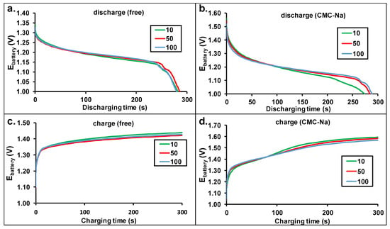
Figure 6.
The cell potential change during the charging and discharging steps (10th, 50th, 100th) of the Zn-air batteries equipped with brass anode without (a,c) or with additive (b,d) in the electrolytes.
In order to get insight into the discharging steps, mathematical modeling has been carried out. First, the generally applied Shepherd model [40,41] was used. This model is represented by Equation (1).
where E0 represents the potential of the battery at full capacity (V), K is the polarization resistant coefficient (Ω), Q is the battery capacity (Ah), I is current (A), R0 is the internal resistance (Ω), I t is the removed charge ( Ah), and A and B are empirical constants (V, A−1h−1). The measured and fitted curves are shown in the left panels of Figure 7.
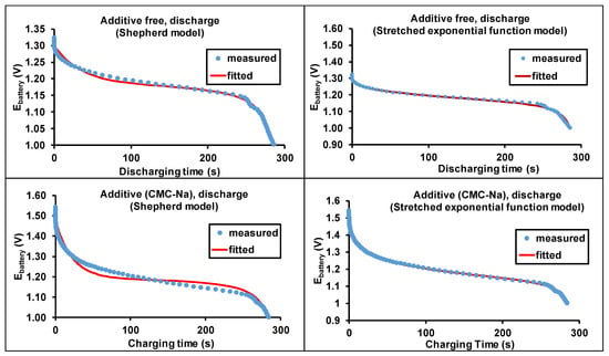
Figure 7.
The measured and calculated discharge curves (50th cycle) for the additive-free and CMC-Na salt-containing batteries.
As seen in Figure 7, the Shepherd model closely describes the discharge curves for both the additive-free and CMC-Na-containing batteries. However, the fittings are not totally convincing, especially in the case of battery with CMC-Na salt-containing electrolyte. Calculations with the Shepherd model showed that the potential decrease in the middle part of the discharging step is smaller than those obtained from the experiments. As we have shown previously [28], the application of stretched exponential function adequately described the potential change of discharge, since numerous parallel reactions take place with slightly different activation energies. The lack of excellent fitting may originate from the more complex electrochemical processes. Therefore, we suggest the modification of the exponential factor to a stretched exponential one [28] in the Shepherd model (Equation (1)), by adding a µ factor to it. Thus, the modified Shepherd equation can be read as:
where the µ is the stretching exponent, all the other parameters were described above (Equation (1)).
The results of the fittings with Equation (2) are shown in the right panel of Figure 7. As seen in Figure 7, excellent fittings were achieved using the modified Shepherd equation (Equation (2)). The obtained polarization-resistant coefficients (K) are similar, but a slight decrease was observed with the use of CMC-Na salt. For the fitting, the capacity was determined by the 50th charging period. The calculated variables of the Shepherd and the modified Shepherd models for the Zn-air battery equipped with a brass anode are compiled in Table 1.

Table 1.
The calculated parameters determined by fitting the Shepherd and the modified Shepherd models.
The relevance of the modified Shepherd model to the calculation of the empirical parameters allows the direct comparison of different batteries. Such a shape for the discharging steps is frequently observed in the case of metal-air batteries, thus our proposed modification of the Shepherd equation is more suitable for the description and characterization of the class of metal-air batteries.
3.4. Morphology
In order to get a deeper insight into the morphology of the electrode surface, SEM measurements were carried out. After finishing the cyclic performance test, the electrodes were washed with water and acetone, the anodes were stored in n-hexane. The SEM images and EDS spectra of the electrodes without or with the use of CMC-Na salt additive, after the cyclic performance test, are shown in Figure 8.
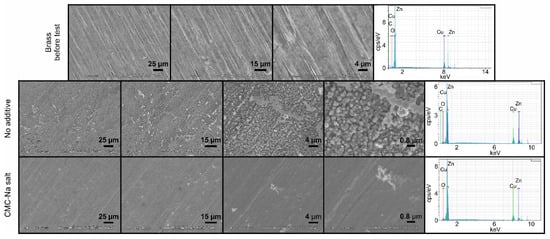
Figure 8.
The SEM images and the EDS spectra of the brass anode, after the long-term cyclic performance test in different magnifications, in the absence and presence of CMC-Na salt additive in the electrolyte.
In the absence of additive, the surface of the electrode was changed and mossy-like deposition was formed, which was not visible to the eyes. The obtained surface was relatively smooth. At higher magnification, the inhomogeneity of the surface become visible. On the EDS spectrum, both copper and zinc were identified. In contrast, the application of CMC-Na salt as an electrolyte modifier results in a smoother surface than without CMC-Na additive. Uniform surface was obtained, which is similar to that of the brass before test and dendrite-free operation was observed even at a high magnification rate. The uniform surface is the result of the positive effect on the regulation of the ion transport; however, as it was discussed above, the energy efficiency is slightly decreased which might be caused by the higher electrical resistance of the cell in the presence of CMC-Na in the electrolyte. Furthermore, the low dendrite formation can be interpreted by the presence of the copper beside the zinc. Under very similar operational conditions, more significant dendrite formation was observed in our previous study using pure zinc foil as anode [28]. As it was shown for Zn-Sn alloys, the presence of an electrochemically inactive metal can aid the uniform stripping during the discharging process and uniform deposition of zinc during the charging process obtaining in this way dendrite-free operation [42]. In addition to the SEM measurements, EDS spectra were also recorded. The presence of copper and zinc is clearly visible, while other elements, identified by XRF, were not detected. This finding may be the result of the cycling performance test since during the test the Zn is concentrated on the surface of the electrode. Both electrolytes are beneficial to suppress the formation of undesirable dendritic deposition.
4. Conclusions
A Cu-Zn alloy (brass) was applied as a Zn anode in our Zn-air battery equipped with a charcoal-based cathode. To investigate the electrochemical processes on the anode, cyclic voltammetry (CV) measurements were carried out. Based on the CV data, different potential ranges for oxidation and reduction of copper and zinc species were identified. Thus, the proper potential range was determined for the Zn-air battery with the brass anode. As an electrolyte, the aqueous solution of KOH (6 M) and K2[(Zn(OH)4)] (0.25 M) was applied with and without additives. CMC-Na salt was applied to increase the viscosity of the electrolyte and achieve high control over the Zn deposition during the charging of the battery. The stable performance of the developed battery was proven by cyclic performance tests up to more than 100 cycles. Narrow and stable working potential ranges were obtained for both electrolyte systems. Additionally, low charging potentials were detected due to the two-electron pathway. Thus, outstanding energy efficiencies were calculated for both electrolyte systems. The energy efficiency of the additive-free battery was 80%, while 75% was obtained with the CMC-Na salt.
The single exponential term in the Shepherd model was replaced by a stretched exponential one, which resulted in excellent fitting for both electrolytes. The morphology of the anode surface was monitored by scanning electron microscopy which showed smooth surface of the brass electrode after the cyclic performance test. Applying the CMC-Na salt additive, the dendrite formation was successfully suppressed.
Supplementary Materials
The following supporting information can be downloaded at: https://www.mdpi.com/article/10.3390/batteries8110212/s1, Figure S1: The exploded-view of the 3D-printed battery.
Author Contributions
Conceptualization, methodology, writing—original draft, T.N.; conceptualization, methodology, writing—original draft, L.N.; methodology, investigation, Z.E.; methodology, investigation, E.B.; methodology, investigation, G.D.; conceptualization, methodology, writing—original draft, supervision, M.Z.; conceptualization, writing—review and editing, supervision, S.K. All authors have read and agreed to the published version of the manuscript.
Funding
The work was supported by the Thematic Excellence Program (TKP2020-NKA-04) of the Ministry for Innovation and Technology in Hungary.
Informed Consent Statement
Not applicable.
Data Availability Statement
Data are available upon request from the corresponding author.
Conflicts of Interest
The authors declare no conflict of interest.
References
- Larcher, D.; Tarascon, J.M. Towards greener and more sustainable batteries for electrical energy storage. Nat. Chem. 2015, 7, 19–29. [Google Scholar] [CrossRef] [PubMed]
- Majumdar, D.; Mandal, M.; Bhattacharya, S.K. Journey from supercapacitors to supercapatteries: Recent advancements in electrochemical energy storage systems. Emergent Mater. 2020, 3, 347–367. [Google Scholar] [CrossRef]
- Girishkumar, G.; McCloskey, B.; Luntz, A.C.; Swanson, S.; Wilcke, W. Lithium-air battery: Promise and challenges. J. Phys. Chem. Lett. 2010, 1, 2193–2203. [Google Scholar] [CrossRef]
- Clark, S.; Latz, A.; Horstmann, B. A Review of Model-Based Design Tools for Metal-Air Batteries. Batteries 2018, 4, 5. [Google Scholar] [CrossRef]
- Buckingham, R.; Asset, T.; Atanassov, P. Aluminum-air batteries: A review of alloys, electrolytes and design. J. Power Sources 2021, 498, 229762. [Google Scholar] [CrossRef]
- Xiong, M.; Clark, M.P.; Labbe, M.; Ivey, D.G. A horizontal zinc-air battery with physically decoupled oxygen evolution/reduction reaction electrodes. J. Power Sources 2018, 393, 108–118. [Google Scholar] [CrossRef]
- Liu, X.; Wang, L.; Yu, P.; Tian, C.; Sun, F.; Ma, J.; Li, W.; Fu, H. A Stable Bifunctional Catalyst for Rechargeable Zinc–Air Batteries: Iron–Cobalt Nanoparticles Embedded in a Nitrogen-Doped 3D Carbon Matrix. Angew. Chem. Int. Ed. 2018, 57, 16166–16170. [Google Scholar] [CrossRef]
- Arico, A.S.; Bruce, P.; Scrosati, B.; Tarascon, J.M.; Schalkwijk, W. Nanostructured materials for advanced energy conversion and storage devices. Nat. Mater. 2005, 4, 366–377. [Google Scholar] [CrossRef]
- Armand, M.; Tarascon, J.M. Building better batteries. Nature 2008, 451, 652–657. [Google Scholar] [CrossRef]
- Han, C.; Cao, W.Q.; Cao, M.-S. Hollow nanoparticle-assembled hierarchical NiCo2O4 nanofibers with enhanced electrochemical performance for lithium-ion batteries. Inorg. Chem. Front. 2020, 7, 4101–4112. [Google Scholar] [CrossRef]
- Yao, L.-H.; Cao, W.-Q.; Shu, J.-C.; Cao, M.-S.; Sun, X.-D. Tailoring adsorption for tunable lithium ion storage and devices. Chem. Eng. J. 2021, 413, 127428. [Google Scholar] [CrossRef]
- Wang, L.; Snihirova, D.; Deng, M.; Vaghefinazari, B.; Xu, W.; Höche, D.; Lamaka, S.V.; Zheludkevich, M.L. Sustainable aqueous metal-air batteries: An insight into electrolyte system. Energy Storage Mater. 2022, 52, 573–597. [Google Scholar] [CrossRef]
- Zhang, J.; Zhou, Q.; Tang, Y.; Zhang, L.; Li, Y. Zinc–air batteries: Are they ready for prime time? Chem. Sci. 2019, 10, 8924–8929. [Google Scholar] [CrossRef] [PubMed]
- Lee, J.S.; Kim, S.T.; Cao, R.; Choi, N.S.; Liu, M.; Lee, K.T.; Cho, J. Metal-air batteries with high energy density: Li-air versus Zn-Air. Adv. Energy Mater. 2010, 1, 34–50. [Google Scholar] [CrossRef]
- Zuoa, Y.; Wang, K.; Pei, P.; Wei, M.; Liua, X.; Xiao, Y.; Zhang, P. Zinc dendrite growth and inhibition strategies. Mater. Today Energy 2021, 20, 100692. [Google Scholar] [CrossRef]
- Shimizu, M.; Hirahara, K.; Arai, S. Morphology control of zinc electrodeposition by surfactant addition for alkaline-based rechargeable batteries. Phys. Chem. Chem. Phys. 2019, 21, 7045–7052. [Google Scholar] [CrossRef]
- Kim, M.; Yun, D.; Jeon, J. Effect of a bromine complex agent on electrochemical performances of zinc electrodeposition and electrodissolution in Zinc-Bromide flow battery. J. Power Sources 2019, 438, 227020. [Google Scholar] [CrossRef]
- Jiang, Y.; Deng, Y.P.; Fu, J.; Lee, D.U.; Liang, R.; Cano, Z.P.; Liu, Y.; Bai, Z.; Hwang, S.; Yang, L.; et al. Interpenetrating Triphase Cobalt-Based Nanocomposites as Efficient Bifunctional Oxygen Electrocatalysts for Long-Lasting Rechargeable Zn-Air Batteries. Adv. Energy Mater. 2018, 8, 1702900. [Google Scholar] [CrossRef]
- Work, A.K.; Ayele, D.W.; Habtu, N.G. Recent advances and future perspectives in engineering of bifunctional electrocatalysts for rechargeable zinc–air batteries. Mater. Today Adv. 2021, 9, 100116. [Google Scholar] [CrossRef]
- Poolnapol, L.; Kao-ian, W.; Somwangthanaroj, A.; Mahlendorf, F.; Nguyen, M.T.; Yonezawa, T.; Kheawhom, S. Silver Decorated Reduced Graphene Oxide as Electrocatalyst for Zinc-Air Batteries. Energies 2020, 13, 462. [Google Scholar] [CrossRef]
- Wang, Y.J.; Fan, H.; Ignaszak, A.; Zhang, L.; Shao, S.; Wilkinson, D.P.; Zhang, J. Compositing doped-carbon with metals, non-metals, metal oxides, metal nitrides and other materials to form bifunctional electrocatalysts to enhance metal-air battery oxygen reduction and evolution reactions. Chem. Eng. J. 2018, 348, 416–437. [Google Scholar] [CrossRef]
- Nagy, T.; Nagy, L.; Erdélyi, Z.; Baradács, E.; Deák, G.; Zsuga, M.; Kéki, S. Environmentally friendly Zn-air rechargeable battery with heavy metal free charcoal based air cathode. Electrochim. Acta 2021, 368, 137592. [Google Scholar] [CrossRef]
- Zhao, S.; Player, L.C.; Bartlett, S.A.; Masters, A.F.; Maschmeyer, T. The Influence of Pyridinium-Based Additives on Zinc Electrodeposition in Aqueous Solution. J. Electrochem. Soc. 2019, 166, D192. [Google Scholar] [CrossRef]
- Kim, H.I.; Shin, H.C. SnO additive for dendritic growth suppression of electrolytic zinc. J. Alloys Compd. 2015, 645, 7–10. [Google Scholar] [CrossRef]
- Xu, Z.; Fan, Q.; Li, Y.; Wang, J.; Lund, P.D. Review of zinc dendrite formation in zinc bromine redox flow battery. Renew. Sustain. Energy Rev. 2020, 127, 109838. [Google Scholar] [CrossRef]
- Garcia, G.; Ventosa, E.; Schuhmann, W. Complete Prevention of Dendrite Formation in Zn Metal Anodes by Means of Pulsed Charging Protocols. ACS Appl. Mater. Interfaces 2017, 9, 18691–18698. [Google Scholar] [CrossRef]
- Wang, K.; Pei, P.; Ma, Z.; Chen, H.; Xu, H.; Chena, D.; Wang, X. Dendrite growth in the recharging process of zinc-air batteries. J. Mater. Chem. A 2015, 3, 22648–22655. [Google Scholar] [CrossRef]
- Nagy, T.; Nagy, L.; Erdélyi, Z.; Baradács, E.; Deák, G.; Zsuga, M.; Kéki, S. Environmentally friendly high performance Zn-air rechargeable battery using cellulose derivatives: A 3D-printed prototype. J. Energy Storage 2022, 49, 104173. [Google Scholar] [CrossRef]
- Liu, Y.; Gao, D.; Xiang, H.; Feng, X.; Yu, Y. Research Progress on Copper-Based Current Collector for Lithium Metal Batteries. Energy Fuels 2021, 35, 12921–12937. [Google Scholar] [CrossRef]
- Ran, Q.; Shi, H.; Meng, H.; Zeng, S.P.; Wan, W.B.; Zhang, W.; Wen, Z.; Lang, X.Y.; Jiang, Q. Aluminum-copper alloy anode materials for high-energy aqueous aluminum batteries. Nat. Commun. 2022, 13, 576. [Google Scholar] [CrossRef]
- Jin, Y.; Chen, F.; Lei, Y.; Wu, X. A Silver-Copper Alloy as an Oxygen Reduction Electrocatalyst for an Advanced Zinc-Air Battery. ChemCatChem 2015, 7, 2377–2383. [Google Scholar] [CrossRef]
- Tan, X.F.; Belyakov, S.A.; Su, T.C.; Gu, Q.; Liu, S.; McDonald, S.D.; Gourlay, C.M.; Yasuda, H.; Matsumura, S.; Nogita, K. Rapid fabrication of tin-copper anodes for lithium-ion battery applications. J. Alloys Compd. 2021, 867, 159031. [Google Scholar] [CrossRef]
- Marioli, J.M.; Kuwana, T. Electrochemical characterization of carbohydrate oxidation at copper electrodes. Electrochim. Acta 1992, 37, 1187–1197. [Google Scholar] [CrossRef]
- He, J.-B.; Lu, D.-Y.; Jin, G.-P. Potential dependence of cuprous/cupric duplex film growth on copper electrode in alkaline media. Appl. Surf. Sci. 2006, 253, 689–697. [Google Scholar] [CrossRef]
- King, F. Corrosion of Copper in Alkaline Chloride Environments; Technical Report, 1404-0344 Contract No.: SKB-TR--02-25; Swedish Nuclear Fuel and Waste Management Co.: Stockholm, Sweden, 2002. [Google Scholar]
- Li, Y.; Lu, J. Metal–Air Batteries: Will They Be the Future Electrochemical Energy Storage Device of Choice? ACS Energy Lett. 2017, 2, 1370–1377. [Google Scholar] [CrossRef]
- Wang, X.; Gao, J.; Cheng, Z.; Chen, N.; Qu, L. A Responsive Battery with Controlled Energy Release. Angew. Chem. Int. Ed. 2016, 55, 14643–14647. [Google Scholar] [CrossRef] [PubMed]
- Lin, C.; Shinde, S.S.; Wang, Y.; Sun, Y.; Chen, S.; Zhang, H.; Li, X.; Lee, J.H. Flexible and rechargeable Zn–air batteries based on green feedstocks with 75% round-trip efficiency. Sustain. Energy Fuels 2017, 1, 1909–1914. [Google Scholar] [CrossRef]
- Nazarov, A.; Thierry, D. Application of Volta potential mapping to determine metal surface defects. Electrochim. Acta 2007, 52, 7689–7696. [Google Scholar] [CrossRef]
- Campagna, N.; Castiglia, V.; Miceli, R.; Mastromauro, R.A.; Spataro, C.; Trapanese, M.; Viola, F. Battery Models for Battery Powered Applications: A Comparative Study. Energies 2020, 13, 4085. [Google Scholar] [CrossRef]
- Shepherd, C.M. Design of Primary and Secondary Cells: II. An Equation Describing Battery Discharge. J. Electrochem. Soc. 1965, 112, 657. [Google Scholar] [CrossRef]
- Peng, Y.; Lai, C.; Zhang, M.; Liu, X.; Yin, Y.; Li, Y.; Wu, Z. Zn–Sn alloy anode with repressible dendrite grown and meliorative corrosion resistance for Zn-air battery. J. Power Sources 2022, 526, 231173. [Google Scholar] [CrossRef]
Publisher’s Note: MDPI stays neutral with regard to jurisdictional claims in published maps and institutional affiliations. |
© 2022 by the authors. Licensee MDPI, Basel, Switzerland. This article is an open access article distributed under the terms and conditions of the Creative Commons Attribution (CC BY) license (https://creativecommons.org/licenses/by/4.0/).